

Page 1

®
MicroTymp
3
portable tympanometric
instrument
Directions for use
Page 2

ii Welch Allyn MicroTymp3 portable tympanometric instrument
REF
© 2009 Welch Allyn. All rights are reserved. No one is permitted to reproduce or duplicate, in any form, this manual or any part
thereof without written permission from Welch Allyn.
Welch Allyn assumes no responsibility for any injury to anyone, or for any illegal or improper use of the product, that may result from
failure to use this product in accordance with the instructions, precautions, warnings, or statement of intended use published in this
manual.
Welch Allyn and MicroTymp are registered trademarks of Welch Allyn.
Software in this product is copyrighted by Welch Allyn or its vendors. All rights are reserved. The software is protected by United
States of America copyright laws and international treaty provisions applicable worldwide. Under such laws, the licensee is entitled
to use the copy of the software incorporated with this instrument as intended in the operation of the product in which it is
embedded. The software may not be copied, decompiled, reverse-engineered, disassembled or otherwise reduced to
human-perceivable form. This is not a sale of the software or any copy of the software; all right, title and ownership of the software
remain with Welch Allyn or its vendors.
For information about any Welch Allyn product, call the nearest Welch Allyn representative:
USA + 1 315 685 4560
Canada 800 561 8797 China + 86 216 327 9631
European Call Center + 35 3 46 906 7790 France + 33 1 60 09 33 66
Germany + 49 7477 92 71 86 Japan + 81 3 3219 0071
Latin America + 1 305 669 9003 Netherlands + 31 15 750 5000
Singapore + 65 6419 8100 South Africa + 27 11 777 7555
United Kingdom + 44 20 7365 6780 Sweden + 46 8 58 53 65 51
102921 (CD)
80015401 Ver A
Welch Allyn, Inc.
4341 State Street Road
Skaneateles Falls, NY 13153 -0220 USA
www.welchallyn.com
800 535 6663
Welch Allyn, Ltd.
Navan Business Park
Dublin Road, Navan
County Meath, Republic of Ireland
Australia + 61 2 9638 3000
800 074 793
Acknowledgments
Welch Allyn gratefully acknowledges the assistance of Robert H. Margolis, Ph.D., of the University of Minnesota for his assistance in
preparing the Interpreting tympanogram results and Glossary sections of this manual.
Page 3

Contents
1 - Introduction . . . . . . . . . . . . . . . . . . . . . . . . . . . . . . . . . . . . . . . . . . . . . 7
iii
About this document . . . . . . . . . . . . . . . . . . . . . . . . . . . . . . . . . . . . . . . . . . . . . . 7
Intended use. . . . . . . . . . . . . . . . . . . . . . . . . . . . . . . . . . . . . . . . . . . . . . . . . . . . . 7
About the device. . . . . . . . . . . . . . . . . . . . . . . . . . . . . . . . . . . . . . . . . . . . . . . . . . 7
Controls, indicators, and connectors . . . . . . . . . . . . . . . . . . . . . . . . . . . . . . . . . . 8
Handle components . . . . . . . . . . . . . . . . . . . . . . . . . . . . . . . . . . . . . . . . . . . . 8
Printer/Charger components . . . . . . . . . . . . . . . . . . . . . . . . . . . . . . . . . . . . . 9
Symbols . . . . . . . . . . . . . . . . . . . . . . . . . . . . . . . . . . . . . . . . . . . . . . . . . . . . . . . 10
General warnings . . . . . . . . . . . . . . . . . . . . . . . . . . . . . . . . . . . . . . . . . . . . . . . . 12
General cautions . . . . . . . . . . . . . . . . . . . . . . . . . . . . . . . . . . . . . . . . . . . . . . . . . 12
General notes . . . . . . . . . . . . . . . . . . . . . . . . . . . . . . . . . . . . . . . . . . . . . . . . . . . 13
Initial setup . . . . . . . . . . . . . . . . . . . . . . . . . . . . . . . . . . . . . . . . . . . . . . . . . . . . . 13
Set up the printer/charger . . . . . . . . . . . . . . . . . . . . . . . . . . . . . . . . . . . . . . 13
Set up the handle . . . . . . . . . . . . . . . . . . . . . . . . . . . . . . . . . . . . . . . . . . . . . 13
Charge the handle . . . . . . . . . . . . . . . . . . . . . . . . . . . . . . . . . . . . . . . . . . . . 15
2 - Completing a test . . . . . . . . . . . . . . . . . . . . . . . . . . . . . . . . . . . . . . . 17
Obtaining a tympanogram . . . . . . . . . . . . . . . . . . . . . . . . . . . . . . . . . . . . . . . . . 17
Select a probe tip . . . . . . . . . . . . . . . . . . . . . . . . . . . . . . . . . . . . . . . . . . . . . 17
Start a test . . . . . . . . . . . . . . . . . . . . . . . . . . . . . . . . . . . . . . . . . . . . . . . . . . 17
Store and display data . . . . . . . . . . . . . . . . . . . . . . . . . . . . . . . . . . . . . . . . . 20
Erase memory contents. . . . . . . . . . . . . . . . . . . . . . . . . . . . . . . . . . . . . . . . 20
Change the default frequency . . . . . . . . . . . . . . . . . . . . . . . . . . . . . . . . . . . 20
3 - Understanding the LCD messages . . . . . . . . . . . . . . . . . . . . . . . . . 23
Company identification . . . . . . . . . . . . . . . . . . . . . . . . . . . . . . . . . . . . . . . . . . . . 23
Frequency confirmation . . . . . . . . . . . . . . . . . . . . . . . . . . . . . . . . . . . . . . . . . . . 23
Open . . . . . . . . . . . . . . . . . . . . . . . . . . . . . . . . . . . . . . . . . . . . . . . . . . . . . . . . . . 24
Test . . . . . . . . . . . . . . . . . . . . . . . . . . . . . . . . . . . . . . . . . . . . . . . . . . . . . . . . . . . 24
Block . . . . . . . . . . . . . . . . . . . . . . . . . . . . . . . . . . . . . . . . . . . . . . . . . . . . . . . . . . 25
Leak . . . . . . . . . . . . . . . . . . . . . . . . . . . . . . . . . . . . . . . . . . . . . . . . . . . . . . . . . . 25
Right store/Left store . . . . . . . . . . . . . . . . . . . . . . . . . . . . . . . . . . . . . . . . . . . . . 26
Right clear/Left clear. . . . . . . . . . . . . . . . . . . . . . . . . . . . . . . . . . . . . . . . . . . . . . 26
Low battery. . . . . . . . . . . . . . . . . . . . . . . . . . . . . . . . . . . . . . . . . . . . . . . . . . . . . 27
Range error . . . . . . . . . . . . . . . . . . . . . . . . . . . . . . . . . . . . . . . . . . . . . . . . . . . . . 27
Zero error . . . . . . . . . . . . . . . . . . . . . . . . . . . . . . . . . . . . . . . . . . . . . . . . . . . . . . 27
Calibration due . . . . . . . . . . . . . . . . . . . . . . . . . . . . . . . . . . . . . . . . . . . . . . . . . . 28
Needs service . . . . . . . . . . . . . . . . . . . . . . . . . . . . . . . . . . . . . . . . . . . . . . . . . . . 28
System check . . . . . . . . . . . . . . . . . . . . . . . . . . . . . . . . . . . . . . . . . . . . . . . . . . . 29
Data Transfer. . . . . . . . . . . . . . . . . . . . . . . . . . . . . . . . . . . . . . . . . . . . . . . . . . . . 29
4 - Interpreting test results. . . . . . . . . . . . . . . . . . . . . . . . . . . . . . . . . . . 31
Tympanograms . . . . . . . . . . . . . . . . . . . . . . . . . . . . . . . . . . . . . . . . . . . . . . . . . . 31
Gradient (width) measurements (226 Hz only) . . . . . . . . . . . . . . . . . . . . . . . . . . 32
226-Hz mode . . . . . . . . . . . . . . . . . . . . . . . . . . . . . . . . . . . . . . . . . . . . . . . . . . . 32
Page 4

iv Contents Welch Allyn MicroTymp3 portable tympanometric instrument
Normative values . . . . . . . . . . . . . . . . . . . . . . . . . . . . . . . . . . . . . . . . . . . . . 32
Interpreting 226-Hz tympanogram results . . . . . . . . . . . . . . . . . . . . . . . . . . . . . 33
Normal middle ear . . . . . . . . . . . . . . . . . . . . . . . . . . . . . . . . . . . . . . . . . . . . 33
Low admittance tympanograms. . . . . . . . . . . . . . . . . . . . . . . . . . . . . . . . . . 33
High admittance tympanograms . . . . . . . . . . . . . . . . . . . . . . . . . . . . . . . . . 34
Negative and positive peak pressure tympanograms (left or right shift) . . . 35
Flat tympanograms . . . . . . . . . . . . . . . . . . . . . . . . . . . . . . . . . . . . . . . . . . . 36
1000-Hz mode . . . . . . . . . . . . . . . . . . . . . . . . . . . . . . . . . . . . . . . . . . . . . . . . . . 37
Tympanometry in young infants . . . . . . . . . . . . . . . . . . . . . . . . . . . . . . . . . . 37
Normative values . . . . . . . . . . . . . . . . . . . . . . . . . . . . . . . . . . . . . . . . . . . . . 38
Interpreting 1000-Hz results . . . . . . . . . . . . . . . . . . . . . . . . . . . . . . . . . . . . . . . . 38
Pass . . . . . . . . . . . . . . . . . . . . . . . . . . . . . . . . . . . . . . . . . . . . . . . . . . . . . . . 38
Refer. . . . . . . . . . . . . . . . . . . . . . . . . . . . . . . . . . . . . . . . . . . . . . . . . . . . . . . 39
Retest. . . . . . . . . . . . . . . . . . . . . . . . . . . . . . . . . . . . . . . . . . . . . . . . . . . . . . 39
Influence of altitude . . . . . . . . . . . . . . . . . . . . . . . . . . . . . . . . . . . . . . . . . . . . . . 40
Influence of temperature . . . . . . . . . . . . . . . . . . . . . . . . . . . . . . . . . . . . . . . . . . 40
5 - Printing 226-Hz results . . . . . . . . . . . . . . . . . . . . . . . . . . . . . . . . . . . 41
Print memory contents . . . . . . . . . . . . . . . . . . . . . . . . . . . . . . . . . . . . . . . . . . . . 41
Printout formats . . . . . . . . . . . . . . . . . . . . . . . . . . . . . . . . . . . . . . . . . . . . . . . . . 42
Tympanogram section . . . . . . . . . . . . . . . . . . . . . . . . . . . . . . . . . . . . . . . . . 42
Data section . . . . . . . . . . . . . . . . . . . . . . . . . . . . . . . . . . . . . . . . . . . . . . . . . 43
Interpretive messages section . . . . . . . . . . . . . . . . . . . . . . . . . . . . . . . . . . . 43
Select printout formats . . . . . . . . . . . . . . . . . . . . . . . . . . . . . . . . . . . . . . . . . . . . 44
Change from manual to automatic printout . . . . . . . . . . . . . . . . . . . . . . . . . 45
Change printout format . . . . . . . . . . . . . . . . . . . . . . . . . . . . . . . . . . . . . . . . 45
Printer function messages . . . . . . . . . . . . . . . . . . . . . . . . . . . . . . . . . . . . . . . . . 47
Printer service codes . . . . . . . . . . . . . . . . . . . . . . . . . . . . . . . . . . . . . . . . . . . . . 47
6 - Maintenance and troubleshooting. . . . . . . . . . . . . . . . . . . . . . . . . . 49
Maintain the equipment . . . . . . . . . . . . . . . . . . . . . . . . . . . . . . . . . . . . . . . . . . . 49
About the battery . . . . . . . . . . . . . . . . . . . . . . . . . . . . . . . . . . . . . . . . . . . . . 49
Replace the tips . . . . . . . . . . . . . . . . . . . . . . . . . . . . . . . . . . . . . . . . . . . . . . 52
Replace the paper . . . . . . . . . . . . . . . . . . . . . . . . . . . . . . . . . . . . . . . . . . . . 52
Cleaning . . . . . . . . . . . . . . . . . . . . . . . . . . . . . . . . . . . . . . . . . . . . . . . . . . . . 54
Functional Checks . . . . . . . . . . . . . . . . . . . . . . . . . . . . . . . . . . . . . . . . . . . . . . . . 55
Check the handle . . . . . . . . . . . . . . . . . . . . . . . . . . . . . . . . . . . . . . . . . . . . . 55
Check the printer/charger. . . . . . . . . . . . . . . . . . . . . . . . . . . . . . . . . . . . . . . 57
A - Middle ear pathologies . . . . . . . . . . . . . . . . . . . . . . . . . . . . . . . . . . 59
Low-admittance pathologies . . . . . . . . . . . . . . . . . . . . . . . . . . . . . . . . . . . . . . . . 59
Otitis media with effusion (OME). . . . . . . . . . . . . . . . . . . . . . . . . . . . . . . . . 59
Middle ear tumor . . . . . . . . . . . . . . . . . . . . . . . . . . . . . . . . . . . . . . . . . . . . . 59
Lateral ossicular fixation . . . . . . . . . . . . . . . . . . . . . . . . . . . . . . . . . . . . . . . . 59
Otosclerosis . . . . . . . . . . . . . . . . . . . . . . . . . . . . . . . . . . . . . . . . . . . . . . . . . 59
Tympanic membrane abnormalities . . . . . . . . . . . . . . . . . . . . . . . . . . . . . . . . . . 59
Ossicular disruption . . . . . . . . . . . . . . . . . . . . . . . . . . . . . . . . . . . . . . . . . . . . . . 60
B - Service and warranty information. . . . . . . . . . . . . . . . . . . . . . . . . . 61
Service . . . . . . . . . . . . . . . . . . . . . . . . . . . . . . . . . . . . . . . . . . . . . . . . . . . . . . . . 61
Repair . . . . . . . . . . . . . . . . . . . . . . . . . . . . . . . . . . . . . . . . . . . . . . . . . . . . . . 61
Calibration . . . . . . . . . . . . . . . . . . . . . . . . . . . . . . . . . . . . . . . . . . . . . . . . . . 61
Warranty . . . . . . . . . . . . . . . . . . . . . . . . . . . . . . . . . . . . . . . . . . . . . . . . . . . . . . . 62
Instrument . . . . . . . . . . . . . . . . . . . . . . . . . . . . . . . . . . . . . . . . . . . . . . . . . . 62
Rechargeable battery . . . . . . . . . . . . . . . . . . . . . . . . . . . . . . . . . . . . . . . . . . 62
Page 5

Directions for use Contents v
C - Specifications . . . . . . . . . . . . . . . . . . . . . . . . . . . . . . . . . . . . . . . . . . 63
Physical characteristics . . . . . . . . . . . . . . . . . . . . . . . . . . . . . . . . . . . . . . . . . . . . 63
Technical specifications. . . . . . . . . . . . . . . . . . . . . . . . . . . . . . . . . . . . . . . . . . . . 64
Probe tone . . . . . . . . . . . . . . . . . . . . . . . . . . . . . . . . . . . . . . . . . . . . . . . . . . 64
Pressure measurement system . . . . . . . . . . . . . . . . . . . . . . . . . . . . . . . . . . 64
Admittance measurement system. . . . . . . . . . . . . . . . . . . . . . . . . . . . . . . . 64
Weight . . . . . . . . . . . . . . . . . . . . . . . . . . . . . . . . . . . . . . . . . . . . . . . . . . . . . 65
Operating environment . . . . . . . . . . . . . . . . . . . . . . . . . . . . . . . . . . . . . . . . 65
Storage environment . . . . . . . . . . . . . . . . . . . . . . . . . . . . . . . . . . . . . . . . . . 65
Battery . . . . . . . . . . . . . . . . . . . . . . . . . . . . . . . . . . . . . . . . . . . . . . . . . . . . . 65
Probe tips . . . . . . . . . . . . . . . . . . . . . . . . . . . . . . . . . . . . . . . . . . . . . . . . . . . 65
Printer paper. . . . . . . . . . . . . . . . . . . . . . . . . . . . . . . . . . . . . . . . . . . . . . . . . 66
Printer/Chargers . . . . . . . . . . . . . . . . . . . . . . . . . . . . . . . . . . . . . . . . . . . . . . 66
Operating ranges . . . . . . . . . . . . . . . . . . . . . . . . . . . . . . . . . . . . . . . . . . . . . 66
Equivalent units and symbols . . . . . . . . . . . . . . . . . . . . . . . . . . . . . . . . . . . . . . . 66
Standards compliance . . . . . . . . . . . . . . . . . . . . . . . . . . . . . . . . . . . . . . . . . . . . 67
Disposal of non-contaminated electrical and electronic equipment Directive
2002/96/EC-WEEE . . . . . . . . . . . . . . . . . . . . . . . . . . . . . . . . . . . . . . . . . . . . 67
Guidance and manufacturer’s declaration. . . . . . . . . . . . . . . . . . . . . . . . . . . . . . 68
Emissions and immunity information . . . . . . . . . . . . . . . . . . . . . . . . . . . . . . 68
D - Replacement parts and accessories . . . . . . . . . . . . . . . . . . . . . . . . 73
Glossary . . . . . . . . . . . . . . . . . . . . . . . . . . . . . . . . . . . . . . . . . . . . . . . . . 75
Page 6

vi Contents Welch Allyn MicroTymp3 portable tympanometric instrument
Page 7

7
Note
1
Introduction
About this document
This document is written for clinical professionals who are qualified to perform
tympanometry. The intended clinical environment is any location where tympanometry is
performed (including but not limited to hospitals, clinics, medical offices, and schools).
This document describes how to operate and maintain the MicroTymp Handle and Printer/
Charger.
Before using the tympanometer — or before setting up, configuring, troubleshooting, or
servicing the device — you must read and understand this document and all other
information that accompanies the tympanometer and its accessories.
Intended use
This device is an auditory impedance tester intended to detect possible otologic disorders
associated with the functioning of the middle ear.
About the device
Federal US law restricts sale of the device identified in this manual to, or on the order of, a
licensed physician.
Using this device’s 226-Hz and 1000-Hz tympanometry settings, you can quickly and
easily obtain objective results supporting diagnosis of otitis media with effusion and other
middle ear disorders. This information can result in more thorough diagnoses as well as
more effective monitoring, treatment, consultation, and referral.
The 226-Hz test data stored in the memory of the Handle may be printed using the
Printer/Charger. The Printer/Charger reads the information from the Handle and prints out
tympanograms and interpretation.
The MicroTymp3 also provides the ability to test patients utilizing a 1000-Hz
frequency mode. This mode features a quick interpretation result that displays a
Pass, Refer, or Retest message on the LCD (see Chapter 4). Results from the
quick interpretation mode can be documented using the 1000-Hz screening
results card. Results from the 1000-Hz quick interpretation mode will not print.
The Printer/Charger also charges the rechargeable battery in the Handle.
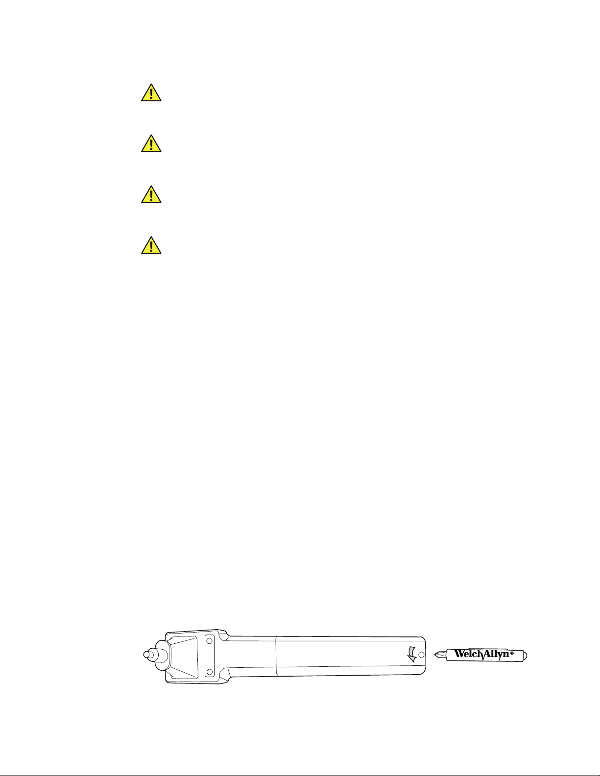
Page 8
8 Introduction Welch Allyn MicroTymp3 portable tympanometric instrument
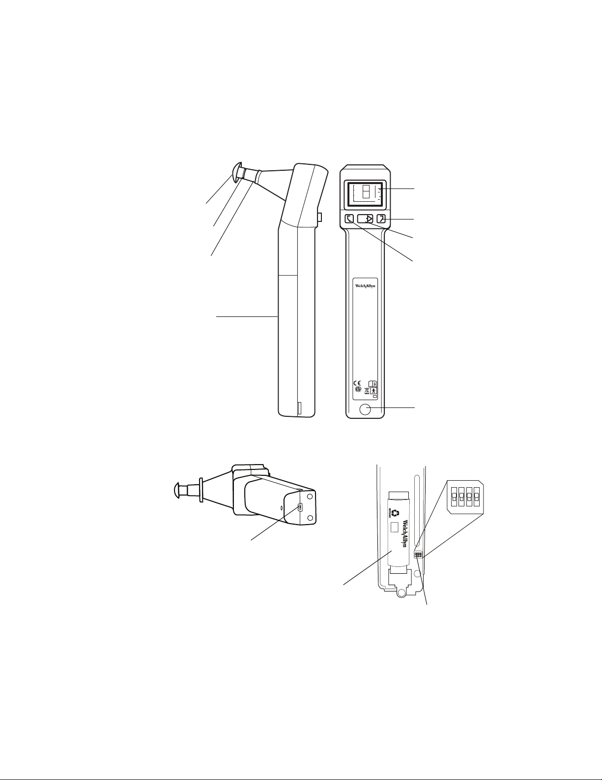
Liquid Crystal
Display (LCD)
Left memory button
Test butto n
Right memory button
Infrared data
transfer window
Tip
Probe
Tip
ejector
Battery
cover
Micro-USB port
NOTE: Reserved for future use
Lithium-ion
battery
Side view Front view
Bottom view
Interior view
Handle
switches
Controls, indicators, and connectors
Handle components
2
GR
1.0
A
1
0.5
GR
Ya - mmho
C
PRESSURE - daPa
TEST
Portable Tympanometric Instrument
MicroTymp
®
3
+200 Vea - cc
0
-400 -200 0 200
C
74227
Patent Pending
IEC TYPE 3
ANSI TYPE 4
Skaneateles Falls, NY USA
0297
US
US Pat #5,383,097
REF
23650
ON
ON CTS
REF
72910
Lithium
Ion
-
ON
ON CTS
+
123
4
OFF
123
OFF
4
Page 9
Directions for use Introduction 9
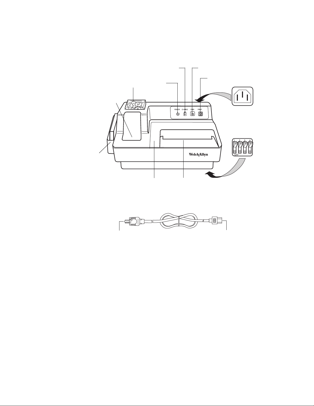
Power Cord
Tip bo x
POWER
indicator
CHARGE
indicator
FEED button
PRINT button
Paper
slot
Paper access
cover
Charging well for
MicroTymp 2 or 3
Card holder
with 1000-Hz
screening
results cards
IEC power cord
receptacle
Printer/Charger
switches
To IEC power
cord receptacle
To pow e r
receptacle
Printer/Charger components
Page 10
10 Introduction Welch Allyn MicroTymp3 portable tympanometric instrument
TEST
GR
A
L
C
GR
-20ºC
+49ºC
95%95%
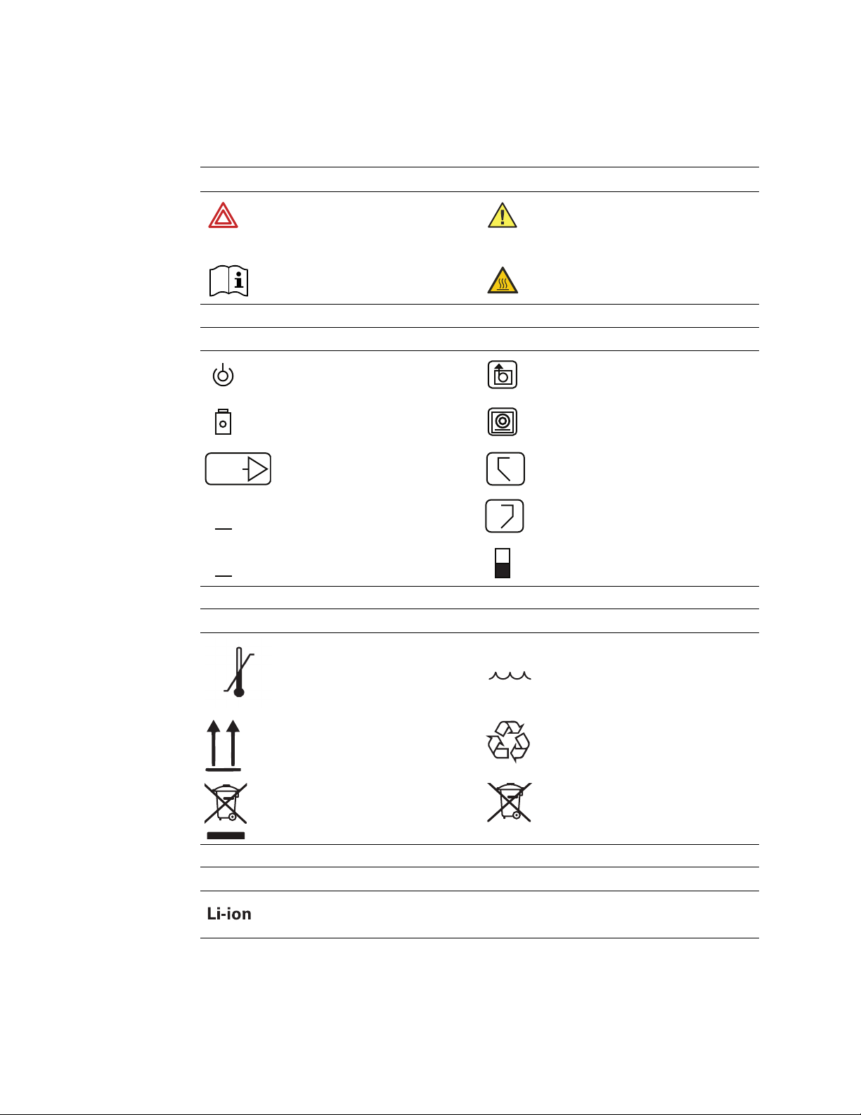
Symbols
Documentation symbols
Warning
(Warnings indicate conditions or practices
that could lead to illness, injury, or death.)
Consult instructions for use Hot surface
Operation symbols
POWER indicator FEED button
CHARGE indicatorPRINT button
TEST button RIGHT memory button
Gradient width adult LEFT memory button
Gradient width child Switch options ON/OFF symbol
Caution
(Cautions indicate conditions or practices
that could damage the equipment or other
property)
R
Shipping, storing, and environment symbols
Temperature limits Relative humidity limit
This end up Recycle
Recycle the product separate from other
disposables. See www.welchallyn.com/
weee for collection point and additional
information.
Power and connectivity symbols
Lithium-ion
Separate batteries from other disposables
for recycling.
Page 11
Directions for use Introduction 11
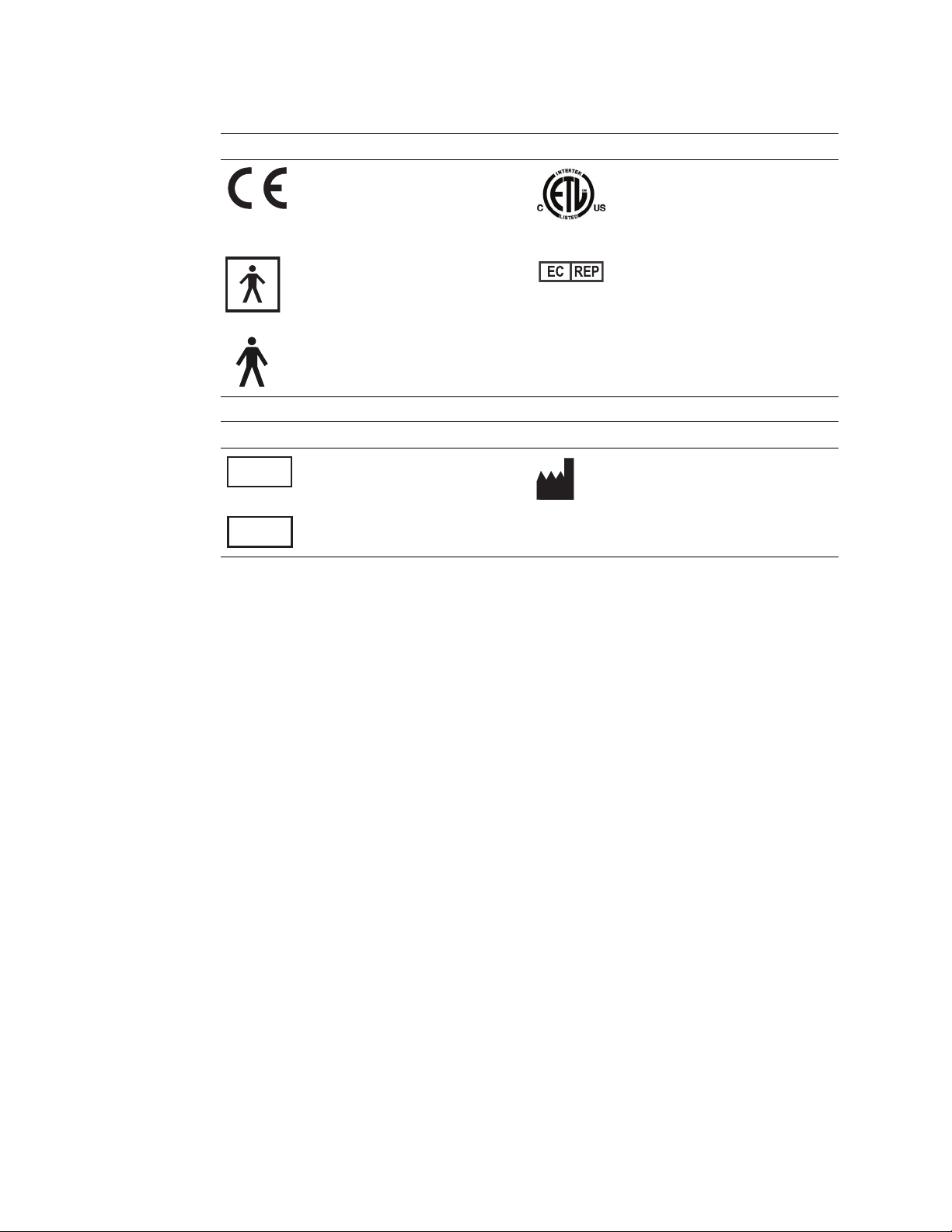
0297
REF
SN
Certification symbols
Meets essential requirements of European
Medical Device Directive 93/42/EEC
74227
Class I equipment, Type BF
(Handle)
Class I equipment, Type B
(Printer/Charger)
Miscellaneous symbols
Reorder number Manufacturer
Complies with applicable U.S. and
Canadian medical safety standards
European regulatory manager
Serial number
Page 12

12 Introduction Welch Allyn MicroTymp3 portable tympanometric instrument
General warnings
WARNING Explosion risk. Do not use MicroTymp Handle or Printer/Charger near
flammable anesthetics.
WARNING Electric shock hazard. Do not attempt to disassemble the Printer/
Charger. Refer all servicing to Welch Allyn or a Welch Allyn authorized service
representative.
WARNING Electric shock hazard. Use the USB connector only to connect to
devices complying with IEC 60601-1 or other IEC standards as appropriate to the
device. The user is responsible for verifying that the system complies with the
requirements of the system standard IEC 60601-1-1 if additional devices are
connected to the MicroTymp Handle.
WARNING Improper handling or disposal of the battery can lead to heat
generation, smoke, bursting, or fire.
WARNING Do not disassemble, modify, or solder the battery.
WARNING Do not directly connect (short circuit) the positive (+) and negative (-)
battery terminals.
WARNING To avoid short circuits, keep the battery terminals away from metal
objects.
WARNING Do not dispose of the battery in fire.
WARNING Do not expose the battery to temperatures above 80°C (176°F).
WARNING Use only the specified charger to charge the battery.
General cautions
Caution Charge only Handle #23640, Handle # 23650, or AudioScope 3
(#23300) in the Printer/Charger.
Caution If the device has not been stored within the operating temperature
range, allow 24 hours minimum for it to return to operating temperature range
(15-35°C or 59-95°F) before using.
Page 13
Directions for use Introduction 13
+
+
+
Caution Do not store either the Handle or Printer/Charger at temperatures
below -20°C (-4°F) or above +49°C (120°F). Continual exposure to extremely low
or high temperatures can permanently damage components.
Caution The battery must be removed if the Handle is to be stored or placed
anywhere other than in the powered Printer/Charger for more than one month.
Failure to do this can result in damage to the Handle.
Caution This instrument contains components which are static sensitive.
Before touching any internal handle component, be sure that you have
discharged any static electricity by touching a grounded metal object.
Caution To prevent equipment damage, charge the Handle only with the
Printer/Charger (#7117x).
General notes
The MicroTymp Printer/Charger (#7117x) will charge and print data from the MicroTymp2
or MicroTymp3 Handle. However, the original MicroTymp Printer/Charger (#7113x) will
neither charge nor print data from the MicroTymp3 Handle.
Please complete and return the warranty registration. It validates the warranty and allows
Welch Allyn to communicate calibration notices and software changes.
Initial setup
Set up the printer/charger
1. Place the Printer/Charger on a flat, horizontal surface.
2. Plug the power cord into the receptacle in the rear of the Printer/Charger, then
connect the power cord to a receptacle with proper voltage, frequency, and plug type.
The solid green POWER indicator will illuminate to indicate that the Printer/Charger is
receiving power.
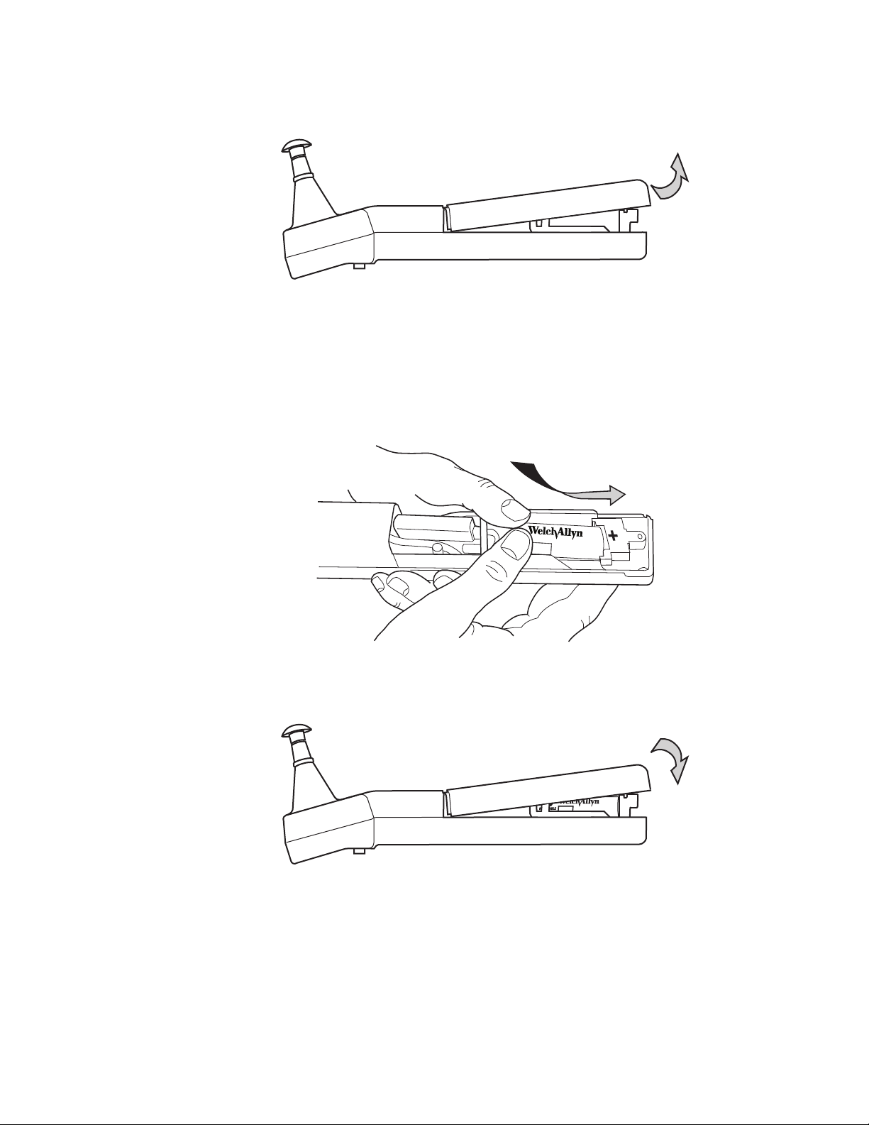
Set up the handle
Install the rechargeable battery in the handle as follows:
1. Unscrew the battery cover in a counterclockwise direction using the #1 Phillips head
screwdriver provided. Save the screw.
Page 14
14 Introduction Welch Allyn MicroTymp3 portable tympanometric instrument
Note
72910
REF
+
Lithium
Ion
72910
REF
+
Lithium
2. Remove the battery cover by lifting the bottom of the cover away from the probe tip.
3. Insert the battery by placing the positive (+) end of the battery against the contact in
the holder. Push the battery lightly to compress the contact, and lower the battery
into the compartment.
Insert the battery only as shown. Failure to observe the correct polarity will
prevent the instrument from functioning.
4. Replace the cover by inserting the tip end under the front cover, lowering the opposite
end, and replacing the screw.
5. Tighten screw in clockwise direction. To avoid stripping the screw threads, do not
tighten excessively.
Page 15

Directions for use Introduction 15
Charge the handle
1. Before first use, place the Handle (with battery installed) into the Printer/Charger
charging well with the LCD and buttons facing you.
2. Leave the Handle in the well for a minimum of 16 hours to achieve a full charge.
You are now ready to take a test. See Ch. 2 for instructions to take a test.
Page 16

16 Introduction Welch Allyn MicroTymp3 portable tympanometric instrument
Page 17
17
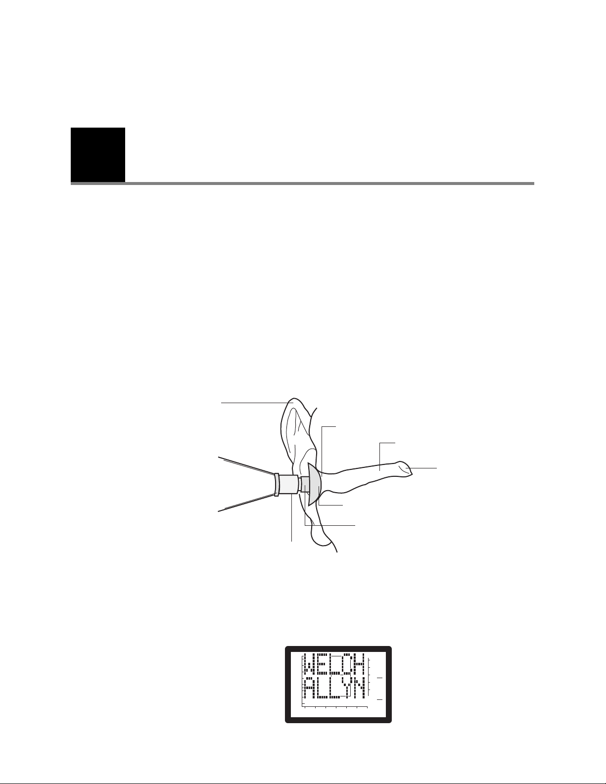
Note
Pinna
Tip ejector
Tip
Probe
Seal
External ear canal
Tym pa ni c
membrane
-400 -200 0 200
2
0.5
0
1.0
1
GR
A
GR
C
PRESSURE - daPa
Ya - mmho
+200 Vea - cc
2
Completing a test
Obtaining a tympanogram
Select a probe tip
1. After examining the subject's ear canal opening, select a tip which is large enough to
seal the entrance of the ear canal.
To change tips, either pull the tip off by hand or slide the tip ejector towards the tip.
Tips are not intended to be deeply inserted into the ear canal. Using an improper
tip size causes leaks, and will make it difficult to complete a test. Use only
MicroTymp3 tips with the MicroTymp3 Handle.
Start a test
2. Push the tip onto the probe, making sure that the tip is fully seated.
1. Pick up the handle and press any button. The Welch Allyn screen will display.
Page 18
18 Completing a test Welch Allyn MicroTymp3 portable tympanometric instrument
Note
Note
-400 -200 0 200
2
0.5
0
1.0
1
GR
A
GR
C
PRESSURE - daPa
Ya - mmho
+200 Vea - cc
R
-400 -200 0 200
2
0.5
0
1.0
1
GR
A
GR
C
PRESSURE - daPa
Ya - mmho
+200 Vea - cc
Time-out feature. The tympanometer automatically turns off 15 seconds after the
last test or button activation.
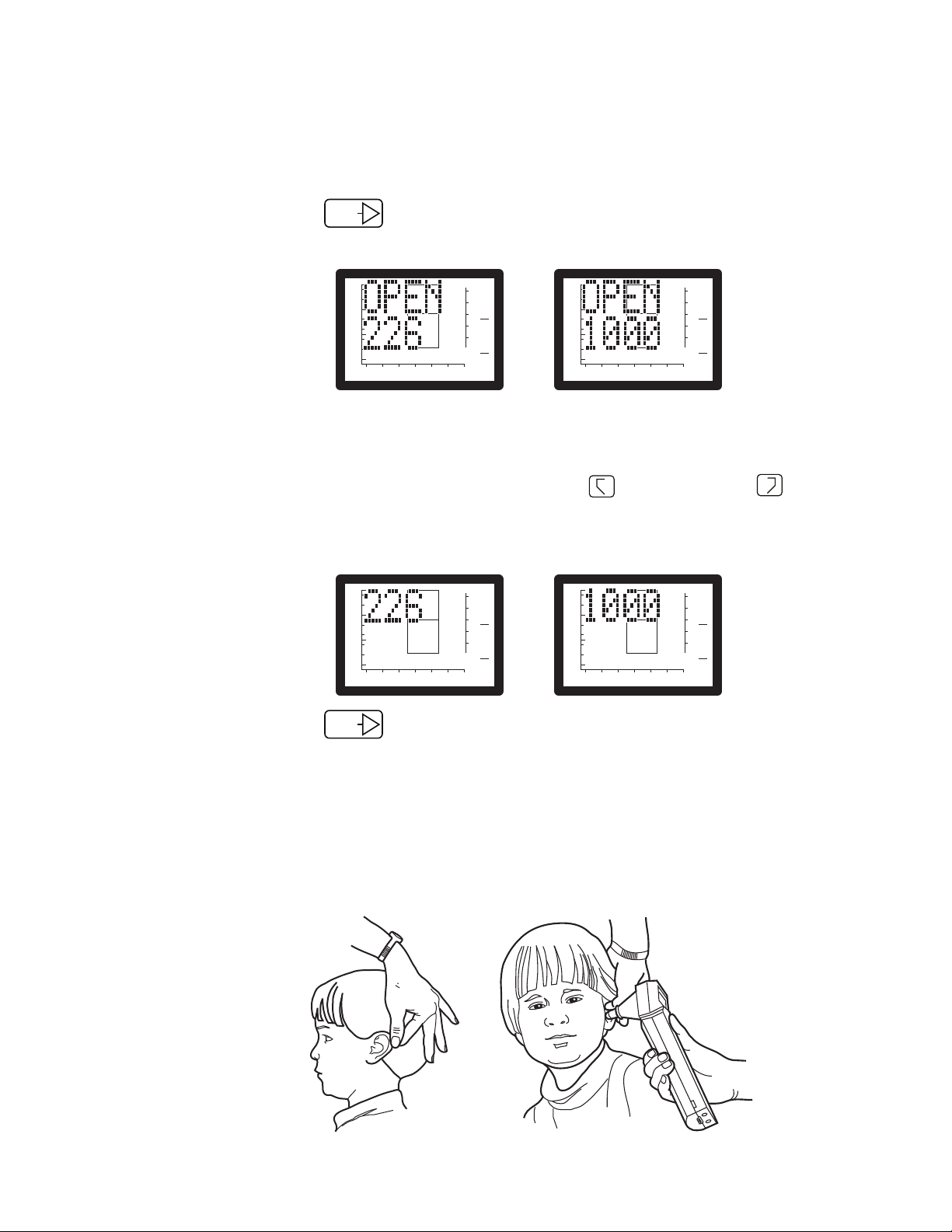
2. Press the button below the Liquid Crystal Display (LCD) to show the
TEST
current frequency. One of the screens shown below will appear.
2
1
GR
A
GR
C
+200 Vea - cc
1.0
0.5
Ya - mmho
0
-400 -200 0 200
PRESSURE - daPa
The default frequency set at the factory is 226 Hz. To change the default
frequency to 1000 Hz, see the instructions at the end of this chapter.
3. To switch to the other frequency, press both the Right memory and Left
L
memory buttons on the handle simultaneously until the desired frequency displays,
as shown below. Pressing the two memory buttons repeatedly toggles between
these two screens.
2
1
GR
A
GR
C
+200 Vea - cc
1.0
0.5
Ya - mmho
0
-400 -200 0 200
PRESSURE - daPa
4. Press the button again to confirm the desired frequency. Either the
TEST
OPEN 226 or OPEN 1000 screen will display, as shown in step 2.
5. Once you’ve confirmed the desired frequency, proceed with the test. Grasp the
subject's pinna. Pull gently back to straighten the child's ear canal (or up and back for
adults). See the image on the left below.
6. While maintaining tension on the pinna, press the tip firmly against the ear canal
opening. See the image on the right below. Point the tip straight into the ear canal for
adults and slightly anteriorly for children.
Page 19
Directions for use Completing a test 19
Note
Note
RLTEST
-400 -200 0 200
2
0.5
0
1.0
1
GR
A
GR
C
PRESSURE - daPa
Ya - mmho
+200 Vea - cc
Note
Because of changes in air pressure during a test, the subject will feel slight
pressure in the ear canal. During the brief seconds when tympanometric
measurements are made, it is important that the clinician's hand is steady, and
that the subject does not talk, yawn, chew gum, cry, or move the head.
If the BLOCK, LEAK, or OPEN messages appear during the test, reposition the tip
to restart the test.
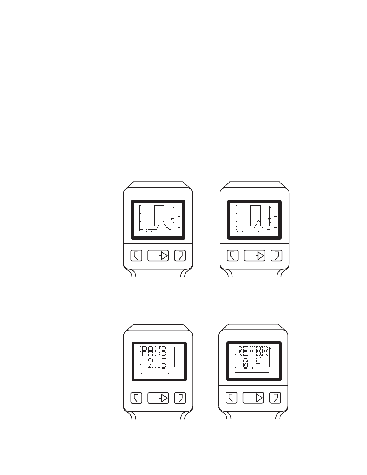
Once a seal is achieved, the TEST message appears on the LCD, followed by the volume
indication on the +200 Vea scale.
For 226 Hz, data points are displayed from right to left across the LCD as the test
progresses. The test is complete when the last data point is displayed. The image below
on the left illustrates the execution of a complete test. If patient or instrument movement
causes a leak beyond -100 daPa in 226-Hz mode, the test will be stopped but the data will
be saved. See the figure on the right below.
1.0
0.5
Ya - mmho
0
-400 -200 0 200
PRESSURE - daPa
RLTEST
2
GR
A
1
GR
C
+200 Vea - cc
1.0
0.5
Ya - mmho
0
-400 -200 0 200
PRESSURE - daPa
RLTEST
2
GR
A
1
GR
C
+200 Vea - cc
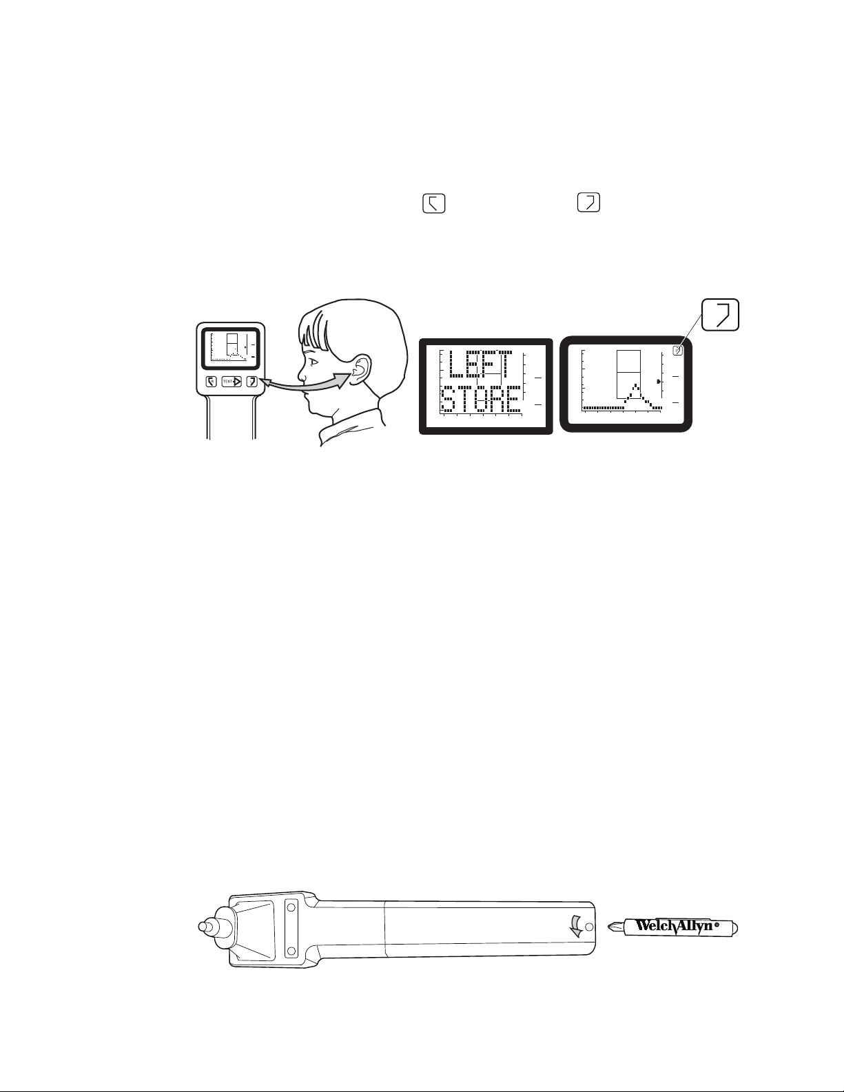
For 1000 Hz, the test is complete when one of two “Quick-Interpretation” messages
appears--either PASS or REFER--as shown in the examples below. If patient or instrument
movement causes a leak beyond -300 daPa in 1000-Hz mode, the test will be stopped but
the data will be saved.
2
1.0
0.5
Ya - mmho
0
-400 -200 0 200
PRESSURE - daPa
GR
A
1
GR
C
+200 Vea - cc
RLTEST
A RETEST message may also appear, indicating that you should rerun the test.
Page 20
20 Completing a test Welch Allyn MicroTymp3 portable tympanometric instrument
R
-400 - 200 0 200
2
0.5
0
1.0
1
GR
A
GR
C
PRESSURE - daPa
Ya - mmho
+200 Vea - cc
L
+
+
+
Store and display data
1. To store the results of the test, press the button which matches the tested ear, as
illustrated below.
The memory buttons are labeled for the right ear and for the left ear. When
test results are stored in memory, the RIGHT STORE or LEFT STORE message
appears momentarily on the LCD. Then the tympanogram which has been stored
reappears along with the right or left symbol (to indicate the contents of that
memory).
2
-400 -200 0 200
PRESSURE - daPa
GR
A
1
GR
C
+200 Vea - cc
Ya - mmho
1.0
0.5
0
2. Press either the Left or Right memory button to recall the information stored in
memory. You may recall memory contents at any time.
Erase memory contents
You can erase memory contents in two ways:
1.0
0.5
Ya - mmho
0
-400 -200 0 200
PRESSURE - daPa
L
2
GR
A
1
GR
C
+200 Vea - cc
• By storing a new test. The device automatically erases the previous test when you
store a new test.
• By pressing either the Left or Right memory button for more than three seconds. This
action erases memory contents for that ear.
Change the default frequency
The default frequency set at the factory is 226 Hz. However, if the majority of your
patients are infants less than six months old, you may set 1000 Hz as the default
frequency. Use the procedure below to switch from one frequency to another.
1. Allow the Handle to power down.
2. Unscrew the battery cover in a counter clockwise direction using the #1 Philips
screwdriver provided. Save the screw.
Page 21
Directions for use Completing a test 21
72910
REF
+
Lithium
ON CTS
ON
OFF
123
4
ON CTS
ON
OFF
123
4
72910
REF
+
-
Lithium
Ion
ON = 226 Hz
OFF = 1000 Hz
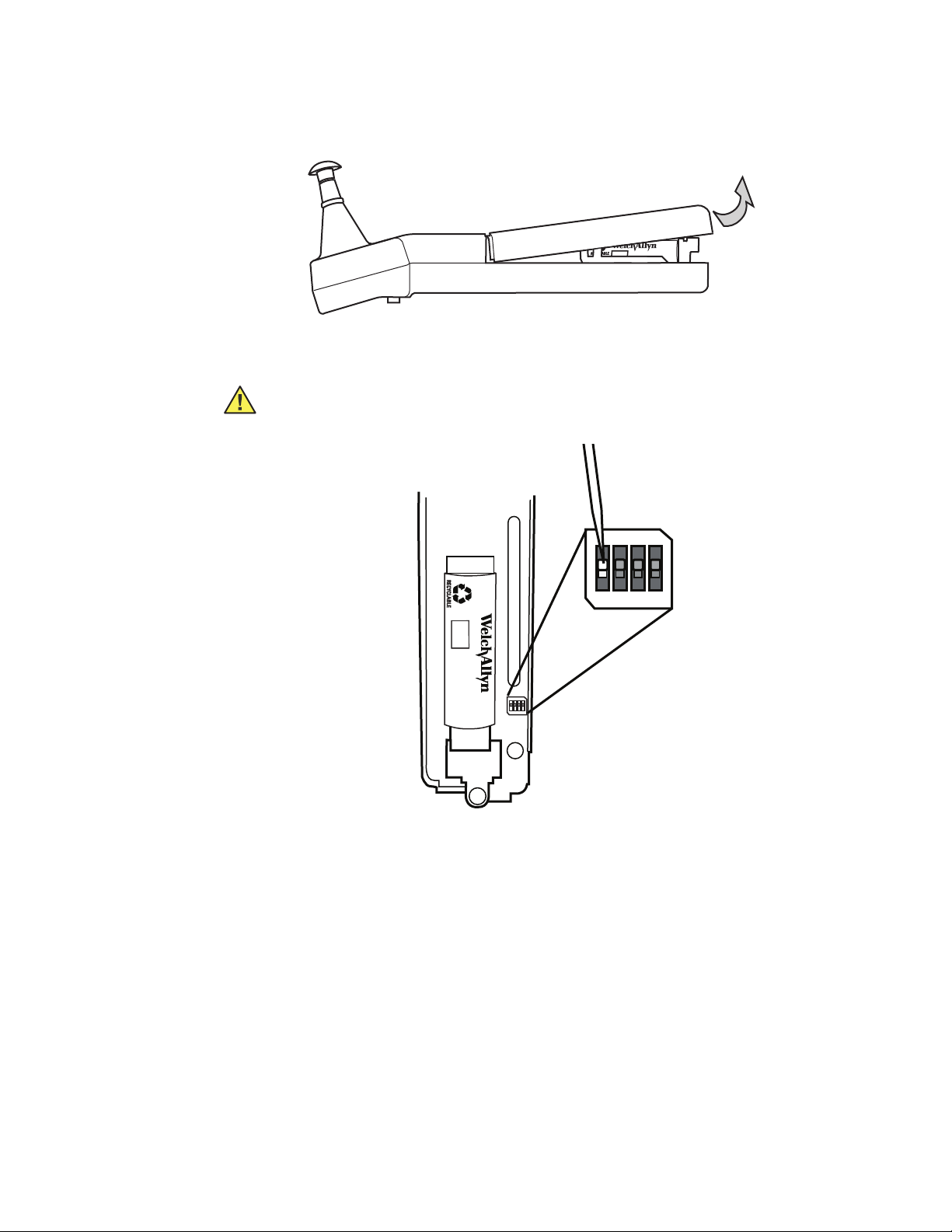
3. Remove the Handle cover by lifting the bottom of the cover away from the probe tip.
4. With a sharp, non-conductive object (like a toothpick or the wooden end of a Q-tip),
move switch 1 to the desired position as shown below.
Caution Potential damage to Handle. Do not use the screwdriver provided or
any other metal object to move the switch.
5. Replace the cover by inserting the tip end under the front cover, lowering the opposite
end, and replacing the screw.
6. Tighten the screw in a clockwise direction. To avoid stripping the screw threads, do
not tighten excessively.
Page 22

22 Completing a test Welch Allyn MicroTymp3 portable tympanometric instrument
Page 23
23
-400 -200 0 200
2
0.5
0
1.0
1
GR
A
GR
C
PRESSURE - daPa
Ya - mmho
+200 Vea - cc
-400 -200 0 200
2
0.5
0
1.0
1
GR
A
GR
C
PRESSURE - daPa
Ya - mmho
+200 Vea - cc
R
L
TEST
3
Understanding the LCD messages
The following messages may be displayed on the LCD during Handle operation.
Company identification
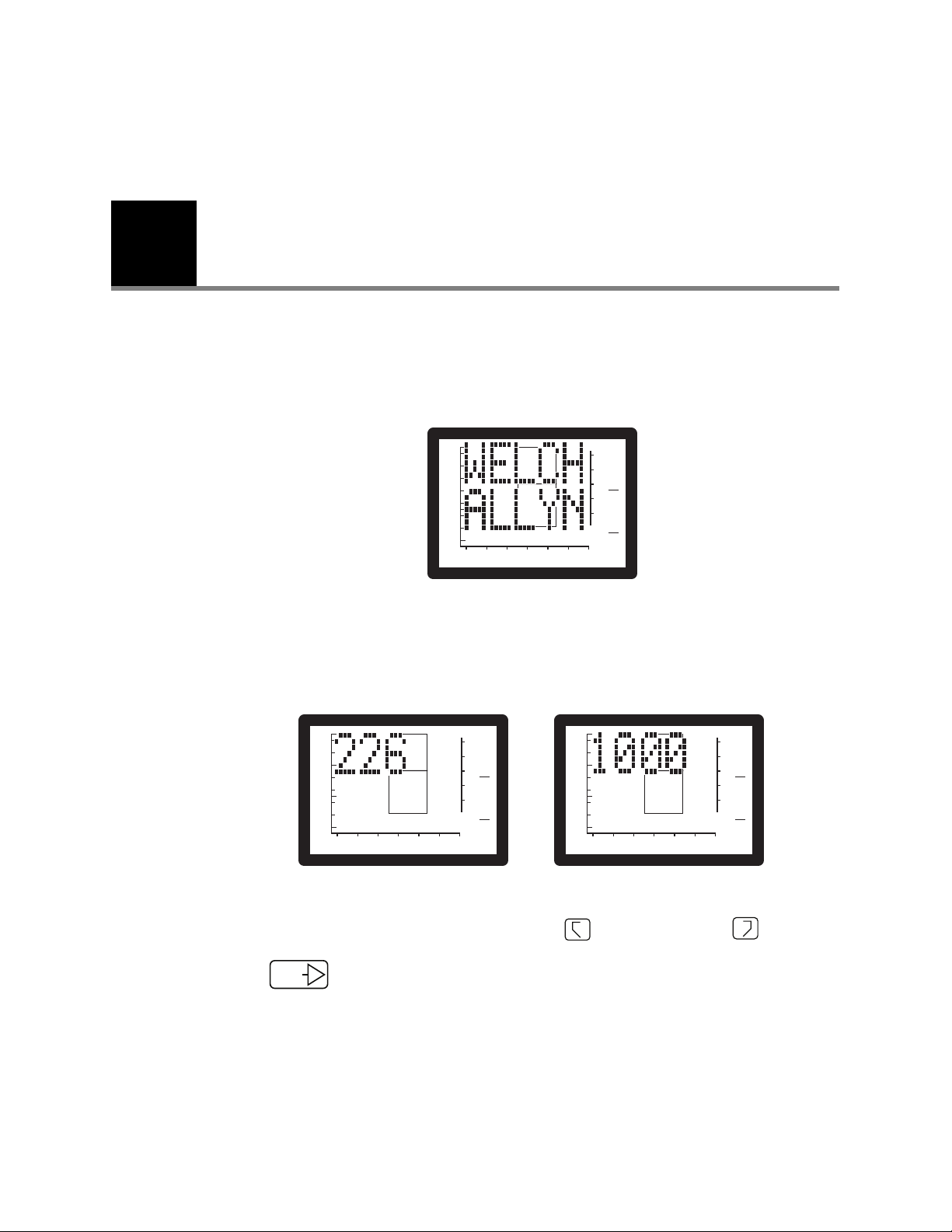
The Welch Allyn message will appear when you press any button.
Frequency confirmation
1.0
0.5
Ya - mmho
0
-400 -200 0 200
PRESSURE - daPa
2
1
GR
A
GR
C
+200 Vea - cc
These messages indicate the unit’s frequency options. You can toggle between
frequencies by simultaneously pressing both the Right memory and Left
memory buttons.
Press to confirm selected frequency and to exit frequency confirmation mode.
Page 24

24 Understanding the LCD messages Welch Allyn MicroTymp3 portable tympanometric instrument
Open
1.0
0.5
Ya - mmho
0
-400 -200 0 200
PRESSURE - daPa
2
1
GR
A
GR
C
+200 Vea - cc
1.0
0.5
Ya - mmho
0
-400 -200 0 200
PRESSURE - daPa
2
1
GR
A
GR
C
+200 Vea - cc
The test has not begun since a valid ear cavity has not been detected.
Possible causes:
• Instrument is not in an ear
• Probe tip is not completely sealed in an ear
• Perforated tympanic membrane
• Ear with patent tympanostomy tubes
• Extremely large canal (> 2.5 cc)
Possible solutions:
• Reposition the probe tip
• Perform otoscopy to check for perforated membrane or patent tympanostomy tubes
Test
1.0
0.5
Ya - mmho
0
-400 -200 0 200
PRESSURE - daPa
2
1
GR
A
GR
C
+200 Vea - cc
1.0
0.5
Ya - mmho
0
-400 -200 0 200
PRESSURE - daPa
2
1
GR
A
GR
C
+200 Vea - cc
The TEST message indicates that the test has started. Test data will begin to appear
immediately.
Page 25

Directions for use Understanding the LCD messages 25
Block
The test cannot continue since the measured admittance is less than 0.2 mmho.
Possible causes:
• Probe tip is lodged against canal wall
• Ear canal occluded
• Collapsed ear canal
• Extremely small ear
• Probe tip is clogged with cerumen
Leak
Possible solutions:
• Reposition the probe tip
• Perform otoscopy to check for occlusion
• Remove cerumen from probe tip
2
1
GR
A
GR
C
+200 Vea - cc
1.0
0.5
Ya - mmho
0
-400 -200 0 200
PRESSURE - daPa
The test cannot proceed since desired pressures within the ear have not been achieved.
Possible causes:
• Probe tip is not completely sealed in the ear canal
• Excessive movement of patient or practitioner
• Probe tip dislodged during a test
Page 26

26 Understanding the LCD messages Welch Allyn MicroTymp3 portable tympanometric instrument
-400 -200 0 200
2
0.5
0
1.0
1
GR
A
GR
C
PRESSURE - daPa
Ya - mmho
+200 Vea - cc
-400 -200 0 200
2
0.5
0
1.0
1
GR
A
GR
C
PRESSURE - daPa
Ya - mmho
+200 Vea - cc
-400 -200 0 200
2
0.5
0
1.0
1
GR
A
GR
C
PRESSURE - daPa
Ya - mmho
+200 Vea - cc
Possible solutions:
• Reposition probe tip
• Patient and practitioner must remain still
• Use a different size probe tip
• Increase pressure against the ear
If a leak condition occurs after -100 daPa pressure is reached at 226 Hz, results will remain
on the display. If an identifiable peak is displayed at 226 Hz, you do not have to repeat the
test. If no peak can be identified, repeat the test and try repositioning the tip, using a
different size tip, or increasing the pressure against the ear canal opening.
If a leak condition occurs after -300 daPa pressure is reached at 1000 Hz, the PASS,
REFER, or RETEST results will be displayed.
Right store/Left store
2
1
GR
A
GR
C
+200 Vea - cc
1.0
0.5
Ya - mmho
0
-400 -200 0 200
PRESSURE - daPa
Test results have been stored in the designated memory location. Immediately following
this message, the newly-stored tympanogram reappears along with the right or left
symbol. For instructions on storing and erasing data, see Chapter 2.
Right clear/Left clear
The designated right or left memory location contains no data. Either no data has been
stored or previously stored data has been erased. See Ch. 2 for information on storing and
erasing data.
Page 27

Directions for use Understanding the LCD messages 27
Low battery
2
1
GR
A
GR
C
+200 Vea - cc
1.0
0.5
Ya - mmho
0
-400 -200 0 200
PRESSURE - daPa
The LOW BATT message indicates that the battery needs to be recharged. The system
will not perform a test in a LOW BATT condition. All buttons are disabled to prevent
inaccurate results due to inadequate battery voltage. Normal operation may be restored
by recharging the battery or replacing the battery with a charged battery. Stored data is
not lost when the battery is removed.
See Chapter 6, “Maintenance and troubleshooting,” for instructions on removing and
recharging the battery.
Range error
The RANGE ERROR message indicates that a large pressure change occurred during a
test. If this message appears, press the TEST button and start the test again.
Zero error
1.0
0.5
Ya - mmho
0
-400 -200 0 200
PRESSURE - daPa
2
1
GR
A
GR
C
+200 Vea - cc
The ZERO ERROR message indicates that a large pressure change occurred during
automatic pressure compensation at the start of a test. If this message appears, press
the TEST button and start the test again.
Page 28

28 Understanding the LCD messages Welch Allyn MicroTymp3 portable tympanometric instrument
-400 -200 0 200
2
0.5
0
1.0
1
GR
A
GR
C
PRESSURE - daPa
Ya - mmho
+200 Vea - cc
Note
-400 -200 0 200
2
0.5
0
1.0
1
GR
A
GR
C
PRESSURE - daPa
Ya - mmho
+200 Vea - cc
Calibration due
Welch Allyn recommends annual calibration of your tympanometer to ensure equipment
accuracy. The CAL DUE message will display each time the device is powered on when
one year has passed since the last calibration. Press and hold the TEST button for
approximately two seconds to clear this message and resume patient testing or print
information stored in the Handle.
Appropriate charges will apply each time your tympanometer is calibrated.
Needs service
The NEEDS SVC message appears when something has caused the tympanometer to fail
an internal test. The NEEDS SVC message will display for approximately three seconds;
then the device will power down. Return the tympanometer to a Welch Allyn service
location for service. (See Service information.)
After each service, the device must be calibrated. Appropriate charges will apply
each time your tympanometer is calibrated.
Page 29

Directions for use Understanding the LCD messages 29
Note
-400 -200 0 200
2
0.5
0
1.0
1
GR
A
GR
C
PRESSURE - daPa
Ya - mmho
+200 Vea - cc
-400 -200 0 200
2
0.5
0
1.0
1
GR
A
GR
C
PRESSURE - d aPa
Ya - mmho
+200 Vea - cc
-400 -200 0 200
2
0.5
0
1.0
1
GR
A
GR
C
PRESSURE - daPa
Ya - mmho
+200 Vea - cc
System check
The SYS CHK (SYS CHK0, SYS CHK1) message indicates that the Handle is doing a selfcheck to ensure proper operation. The Handle will shut off upon completion of the test.
Press any button to power the Handle and clear the condition.
If these messages persist, the Handle requires service. Return the tympanometer to a
Welch Allyn service location for service. (See Service information.)
After each service, the device must be calibrated. Appropriate charges will apply
each time your tympanometer is calibrated.
Data Transfer
When the DATA XFER message displays, the device has made the data connection to the
Printer/Charger. Any 226-Hz data stored in the Handle is now available for printing.
1.0
0.5
Ya - mmho
0
-400 -200 0 200
PRESSURE - daPa
2
1
GR
A
GR
C
+200 Vea - cc
Page 30

30 Understanding the LCD messages Welch Allyn MicroTymp3 portable tympanometric instrument
Page 31

31
4
Interpreting test results
When measured properly, tympanometric results are accurate and objective but should
be interpreted in the context of the patient’s overall clinical condition.
Tympanograms
Key characteristics of the tympanogram
Static Admittance (Peak Ya) is a calculated measure of the compensated static acoustic admittance (height)
1
of the tympanometric peak reported in acoustic s (mmho). Given appropriate normative values, static
admittance (Peak Ya) is a useful indicator of middle ear disease.
Ty mp anometric Gradient (GR) is a measure of the width of the tympanogram reported in decapascals (daPa)
2
at 50% of static admittance (Peak Ya) or the tympanometric peak. Given appropriate normative values,
tympanometric gradient is a good indicator of the presence of middle ear effusion.
Ty mp anometric Peak Pressure (TPP) is the location of the tympanometric peak on the pressure axis. TPP is
3
reported in decapascals (daPa). TPP indicates if there is pressure behind the eardrum but usually does not
indicate middle ear disease.
Equivalent Ear Canal Volume (+200 Vea) is an estimate of the volume of air in front of the probe, measured
4
in cubic centimeters (cc). A high volume suggests an eardrum perforation or patent tympanostomy tube.
Perforations can be present when Vea is normal.
Page 32

32 Interpreting test results Welch Allyn MicroTymp3 portable tympanometric instrument
-400 -200 0 200
2
0.5
0
1.0
1
GR
A
GR
C
PRESSURE - daPa
Ya - mmho
+200 Vea - cc
Normal static
admittance and
TPP (Adults)
Normal static
admittance and
TPP (Children)
Admittance
axis
Pressure
axis
Gradient
(Width) Adult
Gradient
(Width) Child
Note
Gradient (width) measurements (226 Hz only)
When a tympanometric tracing is complete, the device measures the gradient or width of
the tympanogram. If the gradient is abnormal, an asterisk will appear on the LCD under
GR/A for the adult's ear (greater than 10 years of age), or GR/C for the child's ear (10 years
of age or younger). A sample of the Liquid Crystal Display appears below.
226-Hz mode
Normative values
The normative values presented in the table below are taken from a study by Margolis and
Heller (1987) and from the "Guidelines for Screening for Hearing Impairments and Middle
Ear Disorders" (1990).
For purposes of tympanometric norms, an adult is defined as a person 10 years of
age or older, and a child as under age 10.
Normative tympanometric values (226 Hz)
Ty mp a nometric Measurement Child's Ear
(Under Age 10)
90% Range
Peak Ya
(Positive Tail Compensation)
Gradient (GR)
(Tympanometric Width)
Tympanometric
Peak Pressure (TPP)
Equivalent Ear Canal
Volume (Vea)
0.2 to 0.9 mmho 0.3 to 1.4 mmho
60 to 150 daPa 50 to 110 daPa
-139 to +11 daPa -83 to 0 daPa
0.4 to 1.0 cc 0.6 to 1.5 cc
Adult's Ear
(Age 10 & Over)
90% Range
Page 33

Directions for use Interpreting test results 33
-400 -200 0 200
2
0.5
0
1.0
1
1.5
PRESSURE - daPa
Ya - mmho
Vea
+200
RIGHT EAR
R
Note
-400 -200 0 200
2
0.5
0
1.0
1
1.5
PRESSURE - daPa
Ya - mmho
Vea
+200
LEFT EAR
L
Interpreting 226-Hz tympanogram results
Normal middle ear
A tympanogram with normal Peak Ya, gradient (width), and tympanometric peak pressure
appears below.
Low admittance tympanograms
Tympanogram with normal Peak Ya and abnormal gradient (width)
Conditions which cause tympanograms with normal height and increased width:
• Otitis media with effusion
• Tympanosclerosis
Low Peak Ya of the middle ear is produced by space-occupying lesions in various
ways. A lesion that displaces air in the middle ear space causes low admittance
by reducing the middle ear volume. The lesion also may interfere with the
vibration of the ossicular chain, contributing to the low admittance. If the lesion is
in contact with the eardrum, low admittance is a result of interference with
eardrum vibration.
Page 34

34 Interpreting test results Welch Allyn MicroTymp3 portable tympanometric instrument
-400 -200 0 200
2
0.5
0
1.0
1
1.5
PRESSURE - daPa
Ya - mmho
Vea
+200
LEFT EAR
L
Note
-400 -200 0 200
2
0.5
0
1.0
1
1.5
PRESSURE - daPa
Ya - mmho
Vea
+200
RIGHT EAR
R
High Peak Ya
Tympanogram with low Peak Ya
Conditions which cause tympanograms with reduced peak height (low Peak Ya):
• Otitis media with effusion
• Tympanosclerosis
•Cholesteatoma
• Middle ear tumor
See Appendix A for descriptions of low-admittance pathologies: otitis media with effusion,
middle ear tumor, ossicular fixation, and otosclerosis.
High admittance tympanograms
Tympanogram with high Peak Ya
Conditions which cause tympanograms with increased peak height (high Peak Ya):
• Tympanic membrane abnormalities
• Ossicular disruption
When peak admittance exceeds 1.5 mmho, data points will be printed at baseline
(0.0 mmho), as shown above.
See Appendix A for a description of tympanic membrane abnormalities and ossicular
disruption.
Page 35

Directions for use Interpreting test results 35
Note
Note
-400 -200 0 200
2
0.5
0
1.0
1
1.5
PRESSURE - daPa
Ya - mmho
Vea
+200
RIGHT EAR
R
Negative and positive peak pressure tympanograms (left or right shift)
Tympanogram with negative middle ear pressure
LEFT EAR
1.5
1.0
0.5
Ya - mmho
0
-400 -200 0 200
PRESSURE - daPa
Conditions which cause negative middle ear pressure:
• Eustachian tube dysfunction
•Cold
• Allergies
• Vigorous sniffing
Negative pressure within the middle ear space will produce a tympanogram with
a negative tympanometric peak pressure. Some degree of negative pressure is
normal. Negative middle ear pressure often accompanies a cold or allergies, or
can be a result of eustachian tube dysfunction. Negative middle ear pressure is
not usually associated with effusion when peak Ya is normal. Vigorous sniffing
may be the most common cause of negative tympanometric peak pressure in
children.
Vea
+200
2
1
Tympanogram with positive middle ear pressure
Condition which causes positive middle ear pressure:
• Acute otitis media
Positive tympanometric peak pressure tympanograms reflect positive pressure
in the middle ear space. A high positive Tympanometric Peak Pressure (TPP) can
be indicative of acute otitis media, but only if the tympanometric peak is
extremely positive.
Page 36

36 Interpreting test results Welch Allyn MicroTymp3 portable tympanometric instrument
-400 -200 0 200
2
0.5
0
1.0
1
1.5
PRESSURE - daPa
Ya - mmho
Vea
+200
LEFT EAR
Note
-400 -200 0 200
2
0.5
0
1.0
1
1.5
PRESSURE - daPa
Ya - mmho
Vea
+200
LEFT EAR
Flat tympanograms
Flat tympanogram with normal ear canal volume
Condition which causes a flat tympanogram with normal ear canal volume:
• Middle ear effusion
Flat tympanogram with increased ear canal volume
Conditions which cause flat graph and increased ear canal volume:
• Patent tympanostomy tube
• Perforated tympanic membrane
This condition may produce a persistent OPEN message if measured Vea is
greater 2.5 cc. See page 24.
Page 37

Directions for use Interpreting test results 37
Note
-400 -200 0 200
2
0.5
0
1.0
1
1.5
PRESSURE - daPa
Ya - mmho
Vea
+200
RIGHT EAR
R
Tympanograms with artifact
Conditions which cause artifact:
• Patient movement
• Practitioner movement
• Vocalizing or crying
During the typanometric measurement, the clinician should keep a steady hand,
and the patient should not talk, chew gum, yawn, cry, or move. If the display
indicates too much artifact, the clinician must repeat the measurement.
1000-Hz mode
Tympanometry in young infants
Tympanograms obtained with a 226-Hz probe tone have been found to be insensitive to
middle ear fluid in young infants. Recent studies using a 1000-Hz probe tone have shown
good sensitivity to middle ear disease in this population. Research suggests the age at
which 226-Hz tympanometry becomes an appropriate test is between four and six
months. An appropriate guideline for selecting the appropriate age-based frequency is to
use 1000-Hz tympanometry for infants below four months of age, 226-Hz for infants
above six months of age, and both frequencies for infants four to six months of age.
The “Quick-Interpretation” feature of this tympanometer enables clinicians to test infants
less than six months old and receive immediate interpretive feedback from the device.
The 1000-Hz interpretations are based on proven clinical criteria, including calculated
values in the shape of the curve.
Page 38

38 Interpreting test results Welch Allyn MicroTymp3 portable tympanometric instrument
Normative values
The table below presents normative values for 1000-Hz tympanometry for NICU babies
and full-term 2- to 4-week-old babies. [Margolis, R.H., Bass-Ringdahl, S., Hanks, W.D.,
Holte, K., Zapala, D.A. Tympanometry in Newborn Infants - 1 KHz Norms. J. Amer. Acad.
Audiol., 14, 383-392, 2003.]
Normative tympanometric values (1000 Hz)
Ty mp a nometric MeasurementNICU
90% Range
Peak Ya
0.6 - 2.7 mmho 0.6 - 4.3 mmho
(Negative Tail Compensation)
Tympanometric
-93 - +53 daPa -133 - +113 daPa
Peak Pressure (TPP)
Interpreting 1000-Hz results
Pass
Ya - mmho
A normal tympanogram will yield a PASS result. The displayed numerical value represents
the compensated admittance.
1.0
0.5
0
-400 -200 0 200
PRESSURE - daPa
2
1
GR
A
GR
C
Full-term
90% Range
+200 Vea - cc
Condition which causes a PASS message:
• Peak Ya greater than or equal to 0.6 mmho
Page 39

Directions for use Interpreting test results 39
Note
-400 -200 0 200
2
0.5
0
1.0
1
GR
A
GR
C
PRESSURE - daPa
Ya - mmho
+200 Vea - cc
Note
-400 -200 0 200
2
0.5
0
1.0
1
GR
A
GR
C
PRESSURE - daPa
Ya - mmho
+200 Vea - cc
Refer
Condition which causes a REFER message:
• Peak Ya is less than 0.6 mmho
Infants with middle ear effusion have lower Peak Ya at 1000 Hz, just as older children have
reduced Peak Ya at 226 Hz. When the Peak Ya is less than 0.6 mmho, the test is indicative
of abnormal middle ear function, most commonly middle ear effusion.
You may choose to retest the patient to confirm a REFER result.
Retest
Certain testing or patient conditions may cause inconclusive results, yielding a
RETEST message on the display. You may interpret a series of RETEST results as
a REFER result.
Page 40

40 Interpreting test results Welch Allyn MicroTymp3 portable tympanometric instrument
Influence of altitude
As the altitude above sea level increases, the admittance of a given volume of air also
increases. Therefore, equivalent ear canal volume (+200 Vea) overestimates actual ear
canal volume as noted in the table below. To estimate ear canal volume, subtract the
appropriate value in the table from the Vea Reading. Altitude can also affect MicroTest
Cavity results. See Functional Checks starting on page 55.
Altitude adjustments for Vea readings
Altitude Adjustment
for 0.2 cc
-1200 ft (-366 m) 0.0 cc 0.0 cc 0.0 cc 0.0 cc 0.0 cc 0.0 cc
0 ft (0 m) 0.0 cc 0.0 cc 0.0 cc 0.0 cc 0.0 cc 0.0 cc
1000 ft (305 m) 0.0 cc 0.0 cc 0.0 cc 0.0 cc 0.0 cc 0.0 cc
2000 ft (610 m) 0.0 cc 0.0 cc 0.0 cc 0.0 cc 0.0 cc 0.1 cc
3000 ft (914 m) 0.0 cc 0.0 cc 0.1 cc 0.1 cc 0.1 cc 0.1 cc
4000 ft (1219 m) 0.0 cc 0.1 cc 0.1 cc 0.1 cc 0.1 cc 0.1 cc
5000 ft (1524 m) 0.0 cc 0.1 cc 0.1 cc 0.1 cc 0.1 cc *
6000 ft (1829 m) 0.1 cc 0.1 cc 0.1 cc 0.2 cc 0.2 cc *
7000 ft (2134 m) 0.1 cc 0.1 cc 0.1 cc 0.2 cc 0.2 cc *
8000 ft (2438 m) 0.1 cc 0.1 cc 0.2 cc 0.2 cc 0.3 cc *
9000 ft (2743 m) 0.1 cc 0.1 cc 0.2 cc 0.3 cc 0.3 cc *
10000 ft (3048 m) 0.1 cc 0.2 cc 0.2 cc 0.3 cc 0.4 cc *
* The MicroTymp3 will read “OPEN” when used on this ear canal volume at this altitude and will not run a test.
Influence of temperature
Adjustment
for 0.5 cc
Adjustment
for 1.0 cc
Adjustment
for 1.5 cc
Adjustment
for 2.0 cc
Adjustment
for 2.4 cc
No corrections for temperature are required with this device.
Page 41

41
Tymp
®
3
Micro
Portable Tympanometric Instrument
-400
-200
0
200
2
0.5
0
1.0
1
GR
A
GR
C
PRESSURE - daPa
Ya - mmho
+200 Vea - cc
-400
-200
0
200
2
0.5
0
1.0
1
GR
A
GR
C
PRESSURE - daPa
Ya - mmho
+200 Vea - cc
Note
5
Printing 226-Hz results
Print memory contents
Follow the steps listed below to print tympanometric data stored in the Handle:
1. Place the Handle in the well with the Liquid Crystal Display (LCD) and buttons facing
you. When the Handle is properly seated in the well, the green CHARGE indicator
illuminates.
2. Press the PRINT button.
3. To feed extra paper, press the FEED button. Paper continues to feed as long as the
button is depressed.
4. To remove the printout, pull the paper forward and to the left or right to tear it along
the cutting edge.
5. To obtain an additional copy of the test results, leave the Handle in the well and press
the PRINT button again. Removing the Handle from the well causes the data to be
removed from the Printer/Charger memory.
• The Printer/Charger has been pre-set at Welch Allyn to print a complete
printout as illustrated below and to print in manual mode. To change formats
or print in automatic mode, follow the instructions on page 45.
• If only one ear has been tested, the memory for the other ear should be
erased (see page 20) so as not to confound current data with data from a
previous patient.
• If only one memory location has data, only one result is printed.
• Do not use transparent adhesive tape on the printed portions of a printout, as
those portions will then fade.
Page 42

42 Printing 226-Hz results Welch Allyn MicroTymp3 portable tympanometric instrument
Tympanogram
section
Data
section
Interpretive messages
section
Printout formats
A complete tympanometric printout is shown below. The printout is divided into three
sections: tympanogram, data, and interpretive messages. Following is a detailed account
of the information presented in each of these sections. For instructions on changing the
format of the printout, see page 45.
Tympanogram section
The tympanogram is a graph which records the admittance of the ear as a function of air
pressure.
Page 43

Directions for use Printing 226-Hz results 43
Data section
The data section displays numeric values for the four key characteristics of the
tympanogram:
• Static Admittance (Peak Ya) is a calculated measure of the compensated static
acoustic admittance (height) of the tympanometric peak reported in acoustic
millimhos (mmho). Given appropriate normative values, static admittance (Peak Ya) is
a useful indicator of middle ear disease.
• Tympanometric Gradient (GR) is a measure of the width of the tympanogram
reported in decapascals (daPa) at 50% of static admittance (Peak Ya) or the
tympanometric peak. Given appropriate normative values, tympanometric gradient is
a good indicator of the presence of middle ear effusion.
• Tympanometric Peak Pressure (TPP) is the location of the tympanometric peak on
the pressure axis. TPP is reported in decapascals (daPa). TPP indicates if there is
pressure behind the eardrum but usually does not indicate middle ear disease.
• Equivalent Ear Canal Volume (+200 Vea) is an estimate of the volume of air in front
of the probe, measured in cubic centimeters (cc). A high volume suggests an eardrum
perforation or patent tympanostomy tube. Perforations can be present when Vea is
normal.
If the numeric values are greater or less than the 90th percentile of the normative data for
a child or an adult, an asterisk appears under the C(hild) or A(dult) column. The normative
data are listed in the table on page 32.
For the following tympanometric results, no data will be printed:
• 1000-Hz results
• Peak Ya is greater than 1.5 mmho. The message "High Peak Ya" will appear at the top
of the tympanogram.
• Peak Ya less than 0.3 mmho.
• Peak Ya which is incomplete; for example, a negative pressure tympanogram which is
so far negative that the peak has not been reached and data are incomplete.
• Tympanogram has too much artifact. Artifact is generally caused by movement of the
subject or the instrument.
Interpretive messages section
The interpretive messages section of the printout provides an interpretive, verbal
description of the tympanometric result.
The computer in the Printer/Charger examines the data for clinically-significant deviations
from the normal values. For example, a tympanogram which is too wide may be indicative
of a developing or resolving otitis media; the message reads "Tympanogram Is Wide.”
The hierarchy of messages displayed is as follows:
Noisy Tympanogram
Low Peak Height, Small Ear Volume
Low Peak Height, Normal Ear Volume
Page 44

44 Printing 226-Hz results Welch Allyn MicroTymp3 portable tympanometric instrument
Low Peak Height, Large Ear Volume
Tympanogram Is Wide
Negative Tympanometric Peak Pressure
Positive Tympanometric Peak Pressure
High Peak Height
Normal Tympanogram
The computer scans the list of messages and prints the first message that applies. The
hierarchy is arranged so that the most clinically-important message is displayed first.
Select printout formats
The four switches used to select the printout format and printer mode of operation are
located on the bottom of the Printer/Charger.
Use a pointed object to depress appropriate ON or OFF portion of the switch.
Page 45

Directions for use Printing 226-Hz results 45
1234
OFF
Note
Tympanogram Only
(Switch 3)
Tympanogram and
Data (Switch 3)
Messages
(Switch 2)
No messages
(Switch 2)
Change from manual to automatic printout
Automatic vs. Manual Printout (Switch #1)
Auto Print Depress the ON portion of the switch to select this option.
1234
OFF
This causes the printout to begin automatically once the
Handle is placed in the well, and data transfer is complete.
Manual Print
In the manual mode, a beep will occur as a reminder that data has been
transmitted; however, it is not necessary to wait for the beep before pressing
the PRINT button.
Change printout format
Use Switches #2 and #3, located on the bottom of the Printer/Charger, to change printout
format. Printout options are shown below.
Depress the OFF portion of the switch to select this option.
This causes the printout to begin only when the PRINT button
is depressed.
1234
OFF
1234
OFF
1234
OFF
1234
OFF
Page 46

46 Printing 226-Hz results Welch Allyn MicroTymp3 portable tympanometric instrument
OFF
1234
1234
OFF
1234
OFF
1234
OFF
1234
OFF
Print interpretive messages (Switch #2)
No messages
Depress the ON portion of the switch to select this option.
This causes messages which interpret the tympanogram to
not be included on the printout.
Refer to the Printout formats section on page 42 for more
information on these messages.
Messages
Depress the OFF portion of the switch to select this option.
This causes the messages which interpret the
tympanograms to be included on the printout.
Print tympanogram only or tympanogram and data (Switch #3)
Tympanogram only
Depress the ON portion of the switch to select this option.
Only the tympanogram and the GR (Width) numeric value will
print.
Tympanogram and data
Manufacturing switch (Switch #4)
Depress the OFF portion of the switch to select this option.
Both the tympanogram and its corresponding numeric data
will print.
This switch is used during manufacturing only. Leave this
switch in the OFF position. The Printer/Charger will not
operate normally if this switch is on.
Page 47

Directions for use Printing 226-Hz results 47
Note
Printer function messages
If tympanometric results are not printed, a message will appear describing the reason.
These messages are listed in the table below.
Printer messages
Printer function message Possible cause Possible solution
No Data
Reinsert Handle
The Handle is not located in the well. Seat the Handle in the well.
The Handle is not seated properly in the
well.
The Handle has a discharged or missing
battery.
The Handle is not functioning properly. Call your nearest Welch Allyn service
Ensure that the Handle is fully seated in
the well with the Liquid Crystal Display
(LCD) and buttons facing you.
Verify battery is in place and charged
(LOW BATT messaged does not appear).
location, distributor, or factory
representative.
No Data
Nothing in Memory
Computer Interface Switch 4
is Set on Bottom of Printer
Printer service codes
When the Printer/Charger is plugged into an electrical outlet, the green POWER indicator
illuminates and the instrument beeps to indicate that the printer is ready for use.
If a problem exists, the green POWER indicator flashes. The number of flashes
corresponds to the specific problems listed in the table below.
Printer/Charger flashing indicators
Number of flashes Problem Solution
One Printer/Charge is out of paper Replace paper.
Two Paper lever is in wrong (forward) position. Return paper to its original, correct position.
Three or More System failure within Printer/Charger. Verify that switch #4 is in the OFF position.
Both right and left memory locations in
the Handle are empty or data stored is in
“Quick-Interpretation” (1000-Hz) mode.
Switch #4 on the Printer/Charger is ON. Turn off Switch #4.
Ensure that data is being stored correctly.
Unplug the Printer/Charger. Wait one minute,
then re-apply power to the instrument. If
Printer/Charger does not return to normal
operation, return it to the nearest Welch Allyn
service location.
If the green POWER indicator is not illuminated, verify connection to live power
source. If the problem persists, return the Printer/Charger to the nearest Welch
Allyn service location.
Page 48

48 Printing 226-Hz results Welch Allyn MicroTymp3 portable tympanometric instrument
Page 49

49
Note
+
+
+
6
Maintenance and troubleshooting
Maintain the equipment
About the battery
The rechargeable Lithium-ion battery is intended for many charge/discharge cycles and is
warranted for two years. The warranty expiration date is imprinted on the battery.
Caution Replace battery with Welch Allyn model #72910 battery only.
Disassembly of the tympanometer beyond the extent described in this manual
will void the warranty. Refer all servicing to Welch Allyn or a Welch Allyn
Authorized Service Representative.
Replace the battery
Replace the rechargeable battery in the handle as follows:
1. Allow the Handle to power down.
2. Unscrew the battery cover in a counterclockwise direction using the #1 Phillips head
screwdriver provided. Save the screw.
3. Remove the battery cover by lifting the bottom of the cover away from the probe tip.
Page 50

50 Maintenance and troubleshooting Welch Allyn MicroTymp3 portable tympanometric instrument
Note
72910
REF
-
72910
REF
+
Lithium
Ion
72910
REF
+
Lithium
4. Push down on the positive (+) end of the battery. The battery will eject.
5. Insert the new battery by placing the positive (+) end of the battery against the
contact in the holder. Push the battery lightly to compress the contact, and lower the
battery into the compartment.
Insert the battery only as shown. Failure to observe the correct polarity will
prevent the instrument from functioning.
6. Replace the cover by inserting the tip end under the front cover, lowering the opposite
end, and replacing the screw.
Page 51

Directions for use Maintenance and troubleshooting 51
Note
Micr
oTymp
®
3
P
o
r
t
a
ble
T
ym
pan
o
me
tri
c In
st
r
u
m
e
nt
0297
IEC TYPE 3
Skaneateles Falls, NY USA
US Pat #5,383,097
ANSI TYPE 4
Patent Pending
C
US
74227
23650
REF
Note
7. Tighten screw in clockwise direction. To avoid stripping the screw threads, do not
tighten excessively.
8. Place the Handle into the charging station for a minimum of 10 seconds to enable the
battery protection circuit.
The unit will not power up if you do not enable the battery protection circuit.
Recharge the battery
To recharge the battery, place the Handle in the Printer/Charger well with the LCD and
buttons facing you.
Caution To prevent equipment damage, charge the Handle only with the
Printer/Charger (#7117x).
The 3.7V Lithium-ion battery used in the Handle, when fully charged, provides a full day of
operation without the need for recharging and yields a minimum of 300 double-ear tests.
This makes the instrument optimal for mass screening or off-site situations where there
may not be a need to print, but there is a need for continuous operation.
A fully drained battery should be recharged overnight (16 hours).
• The Handle may be charged indefinitely without damage to the battery.
• Slight heating of the Handle during charging is normal.
• The battery will self-discharge gradually over a period of approximately 60
days when stored at room temperature (70°F/21°C); storage at higher
temperatures accelerates the discharge rate.
Page 52

52 Maintenance and troubleshooting Welch Allyn MicroTymp3 portable tympanometric instrument
Note
Recycle the Battery
Check with your local waste management agency for the proper recycling procedure for a
Lithium-ion battery.
Lithium-ion battery.
Must be recycled or
disposed of properly.
Replace the tips
Replace the probe tips after six months of use.
Replace the paper
The Printer/Charger signals the need for changing the paper in one of two ways:
• A pink strip appears along the edge of the paper indicating the paper is nearing the
end of the roll.
• The POWER indicator flashes in single pulses indicating that there is no paper, and no
printing can occur.
• Use only an appropriate heat-sensitive paper or the Printer/Charger life may
be shortened and the warranty voided.
• The paper is thermally activated, so it must be stored in a cool, dark location
to prevent exposure and degraded performance.
• Because the paper is thermally activated, no printing will appear on the paper
if it is inserted backwards.
• Do not use transparent adhesive tape on printed portions of the printout, as
those portions will then fade.
WARNING Electric shock hazard. Do not attempt to disassemble the Printer/
Charger. Refer all servicing to Welch Allyn or a Welch allyn authorized service
representative.
1. Remove the paper access cover by pulling up on the front edge.
Page 53

Directions for use Maintenance and troubleshooting 53
Note
2. Depress the FEED button to advance any remaining paper through the printer. Do not
pull paper backwards through the printer. Remove and discard old paper roll. Save the
black spindle that guides the paper.
3. Pull the paper lever forward.
4. Place the roll of paper behind the Printer/Charger for easier handling.
5. Insert the paper (from of the bottom of the roll) into the slot under the pinch roller,
making sure that the paper is centered.
6. Return the paper lever to its original position, and press the FEED button to advance
several inches of paper beyond the pinch roller.
7. Tighten the paper on the paper roll, reinsert the black spindle through the roll, and
place the paper roll in the paper cradle.
8. Feed the paper through the slot in the paper access cover.
Make sure that the paper is taut before replacing the paper access cover. Loose
paper can cause printer malfunction.
9. Replace the cover by sliding the back edge into place first and lowering the front of
the paper access cover.
Page 54

54 Maintenance and troubleshooting Welch Allyn MicroTymp3 portable tympanometric instrument
Cleaning
Clean the handle
Clean the Handle by wiping it with a cloth that has been lightly dampened with 70%
Isopropyl alcohol. Make sure liquid does not seep into the instrument, especially in the
probe area.
Clean the printer/charger
Clean the Printer/Charger by wiping it with a cloth that has been lightly dampened with
70% Isopropyl alcohol. Make sure liquid does not seep into either the printer area or the
charging well.
Clean the probe tips
After each use, inspect small openings in the tip for debris, then remove tip from Handle.
If you observe no debris, wipe with a clean cloth and a 70% isopropyl alcohol solution.
Allow to air dry.
If you observe debris after use, rinse tip with warm tap water for one minute, then soak
the tip in 70% alcohol for 20 minutes. Rinse tip with tap water and air dry.
Page 55

Directions for use Maintenance and troubleshooting 55
Note
M
ic
roTest
CA
VITY
2.0
cc
0.
5
c
c
R
-400
-200
0
200
2
0.5
0
1
.
0
1
GR
A
GR
B
PRE
S
S
U
R
E
-
DaPa
Ya -
m
m
h
o
+
2
0
0
V
e
a
-
cc
TEST button
Functional Checks
Check the handle
A MicroTest Cavity is included with the Handle. The cavity provides a functional test of the
Handle to determine if it is working properly. The 0.5 cc cavity is used to test the Low
Range of ear canal volume (Vea). The 2.0 cc cavity is used to test the High Range of the
ear canal volume (Vea).
Check the Handle with the MicroTest Cavity at least once a month and whenever the
operation of the Handle is questioned.
Functional testing must be done in both the 226-Hz mode and the 1000-Hz mode.
L
226-Hz check
To switch the frequency, simultaneously press and .
R
After completing both tests, you can toggle back to desired frequency by pressing
the same buttons.
1. Make sure the Handle is in 226-Hz mode.
2. Using any size probe tip, place the probe tip against the 0.5 cc cavity as if it were an
ear. Hold the handle and MicroTest Cavity carefully to prevent movement. Depress
the TEST button and test the cavity as you would an ear.
3. Store the information using either the right or left memory buttons.
4. Repeat Steps 2 and 3 using the 2.0 cc cavity. Store the information in the opposite
memory location used in Step 2.
5. Print the information using the Printer/Charger.
Page 56

56 Maintenance and troubleshooting Welch Allyn MicroTymp3 portable tympanometric instrument
Ty mp a nogram from 0.5 cc cavity
Note
A properly functioning instrument will produce two results:
• A flat tympanogram (see the figure below). All data points must fall within the two
bottom rows of the graph.
• An ear canal volume (Vea) which corresponds to the cavity tested. See the Expected
Vea readings table for the acceptable range for each cavity both at sea level and at
different altitudes.
1000-Hz check
Expected Vea readings for MicroTest cavity
Cavity Measured Acceptable
Tol erances
0.5 cc Cavity ±0.1 cc 0.4 cc to 0.6 cc 0.4 cc to 0.6 cc 0.5 cc to 0.7 cc
2.0 cc Cavity
Refer to the Influence of altitude table on page 40 for a more comprehensive treatment of altitude’s effect.
±0.1 cc 1.9 cc to 2.1 cc 2.0 cc to 2.2 cc 2.0 cc to 2.2 cc
Acceptable Range
at Sea Level
Acceptable Range
at 3000 ft (914 m)
Acceptable Range
at 5000 ft (1524 m)
If the readings do not fall within the acceptable range, then the Handle requires
calibration. Send the Handle to a Welch Allyn service location.
As the altitude above sea level increases, the admittance of an air-filled cavity also
increases. Therefore, at altitudes above sea level, results using the MicroTest Cavity will
change.
1. Make sure the Handle is in 1000-Hz mode.
2. Using any size probe tip, place the probe tip against the 0.5 cc cavity as if it were an
ear. Hold the handle and MicroTest Cavity carefully to prevent movement. Depress
the TEST button and test the cavity as you would an ear.
3. Store the information using either the right or left memory buttons.
4. Repeat Steps 2 and 3 using the 2.0 cc cavity. Store the information in the opposite
memory location used in Step 2.
The Handle should display REFER 0.4 or less in both the 0.5 cc and 2.0 cc cavities.
While the MicroTest Cavity provides a functional test, it does not replace full
calibration. Welch Allyn recommends that the Handle be calibrated annually.
Page 57

Directions for use Maintenance and troubleshooting 57
1 Test Pattern
2 Software Version
3 Normative Data Reference
Troubleshooting the Handle
Symptom Possible Cause Possible Solution
Handle does not turn on No battery. Put battery in. Reset the battery protection circuit.
Battery is in backwards. Reposition the battery observing correct polarity. Reset
the battery protection circuit.
Battery is not charged/dead. Charge/replace the battery. Reset the battery
protection circuit.
If symptom still persists, return to local Welch Allyn
service location for service.
Battery protection circuit was
not reset.
Too much artifact on LCD Too much movement during
test.
Handle has too much internal
noise.
Place the Handle in the Printer/Charger for a minimum
of 10 seconds to reset the battery protection circuit.
See page 37.
Check handle in MicroTest cavity. If handle passes
functional check, artifact is due to motion. If handle
does not pass functional check, return to Welch Allyn
service location for service.
“Frozen” display on LCD
OR
“Checkerboard” pattern on
LCD
Check the printer/charger
Pressing the FEED and PRINT buttons simultaneously causes a test pattern to print, as
shown below.
Microcomputer has
malfunctioned.
Push TEST and repeat.
If symptom persists, push all three handle buttons
(TEST, R MEM, L MEM) simultaneously to reset
microcomputer.
If symptom persists, remove and reinsert the battery.
If symptom persists, return to local Welch Allyn service
location for service.
Page 58

58 Maintenance and troubleshooting Welch Allyn MicroTymp3 portable tympanometric instrument
1. Test Pattern - The test pattern is used to confirm that the print head is functioning
properly. If any of the print head elements are not functioning, a white line will appear
vertically down the printout. A defect in the paper may also cause white lines or light
printing. Repeat the test pattern to confirm any suspected printing problems. If paper
advances but nothing prints out, check to be sure the paper is inserted properly (see
page 52).
2. Software Version - The test pattern also includes the software version for the Printer/
Charger.
3. Normative Data Reference - The test pattern is followed by normative data for
tympanometric characteristics for both the MicroTymp2 and MicroTymp3 Handle. This
is provided along with the test pattern for the convenience of the user, not specifically
as a functional check.
Page 59

59
A
Middle ear pathologies
Low-admittance pathologies
Otitis media with effusion (OME)
Otitis media with effusion (OME) is an inflammation of the middle ear accompanied by an
accumulation of fluid. Fluid in the middle ear can cause conductive hearing impairment
when it interferes with the normal vibration of the eardrum by sound waves. In advanced
cases, OME results in flat tympanograms (low Peak Ya). In intermediate stages of OME,
the peak height may be normal, but the gradient may be widened.
Middle ear tumor
A wide variety of neoplastic processes exist that invade the middle ear. The most
common is the keratoma (cholesteatoma), a collection of keratinizing squamous
epithelium that frequently originates from Shrapnel's membrane (pars flaccida) of the
tympanic membrane or the ear canal wall and invades the middle ear space. Other middle
ear tumors include the cholesterol granuloma, glomus tumor, and squamous cell
carcinoma. These pathologies generally result in a flat tympanogram.
Lateral ossicular fixation
Lateral ossicular fixation may result from tympanosclerosis, a complication of chronic
otitis media that may involve the eardrum, malleus, incus, and/or stapes. In general, the
more lateral the fixation, the more effect the condition has on the tympanogram. Lateral
fixations typically cause low Peak Ya and wide tympanometric widths.
Otosclerosis
Because the otosclerotic lesion is more medial than lateral ossicular fixation, the
tympanogram is less affected. The tympanometric shape is often indistinguishable from
normal, although the Peak Ya may be slightly low and the tympanometric gradient (width)
may be narrower than the normal tympanogram.
Tympanic membrane abnormalities
The tympanic membrane is normally a stiff, conically-shaped structure that derives its stiff
characteristic from the lamina propria, a layer of connective tissue that is situated
between the outer layer of squamous epithelium (skin) and the inner layer of mucous
membrane. When the eardrum heals after a relatively large perforation, the lamina propria
may be absent or thin in the region of the scar. This neomembrane can be set into
Page 60

60 Middle ear pathologies Welch Allyn MicroTymp3 portable tympanometric instrument
vibration with greater ease than the normally stiff tympanic membrane. The result is a
high Peak Ya. Although the tympanogram is abnormal, this condition rarely affects hearing
sensitivity or requires further medical treatment.
Ossicular disruption
Disruption of the ossicular chain can range from partial interruption to complete absence
of the ossicles. These conditions result from the erosive effects of chronic infection,
trauma, and congenital defect. Ossicular disruption is usually associated with a substantial
conductive hearing loss. Because the ossicles normally "load" the eardrum, contributing to
its tension, the eardrum in an ear with ossicular disruption can be more easily set into
vibration than the normal eardrum, resulting in high Peak Ya.
Page 61

61
B
Service
Repair
Calibration
Service and warranty information
Repair must be performed by Welch Allyn authorized personnel. Failure to do so
invalidates the warranty. A moderate fee is charged to calibrate the Handle after a repair.
Contact Customer Service in your region for service options.
Welch Allyn recommends that the Handle be calibrated annually. Arrangements may be
made by returning the registration card or by contacting Welch Allyn's Technical Service
Department or an authorized Welch Allyn distributor. A moderate fee is charged for
calibration.
A monthly functional check using the MicroTest Cavity is recommended in addition to
annual calibration.
The Printer/Charger does not require calibration.
Page 62

62 Service and warranty information Welch Allyn MicroTymp3 portable tympanometric instrument
Note
Warranty
Instrument
Welch Allyn Inc. warrants the Handle and Printer/Charger to be free of original defects in
material and workmanship and to perform in accordance with manufacturer's
specifications for a period of one year from the date of purchase. If this instrument or any
component thereof is found to be defective or at variance from the manufacturer's
specifications during the warranty period, Welch Allyn will repair, replace or calibrate the
instrument or component(s) at no cost to the purchaser.
This warranty only applies to instruments purchased new from Welch Allyn or its
authorized distributors or representatives. The purchaser must return the instrument
directly to Welch Allyn or an authorized distributor or representative. Ground shipping
charge to return a defective device to the nearest Welch Allyn center is included.
This warranty does not cover breakage or failure due to tampering, misuse, neglect,
accidents, modification or shipping, and is void if the instrument is not used in accordance
with manufacturer's recommendations or if repaired or serviced by other than Welch Allyn
or a Welch Allyn authorized representative.
Purchase date determines warranty and annual calibration requirements. No other
express or implied warranty is given.
Proof of purchase date is required for warranty validation.
Rechargeable battery
Welch Allyn Lithium-ion batteries are warranted by Welch Allyn for two years from date of
manufacture (when used in Welch Allyn instruments only). Defective batteries under
warranty will be replaced when the unit is sent to Welch Allyn for service.
Page 63

63
3.68 in
9.35 cm
7.32 in
18.6 cm
1.94 in
4.94 cm
9.62 in
24.4 cm
9.70 in
24.6 cm
4.82 in
12.2 cm
POWER
CHARGE FEED PRINT
TEST
-400 -200 0 200
2
0.5
0
1.0
1
GR
A
GR
C
PRESSURE - daPa
Ya - mmho
+200 Vea - cc
MicroTymp
®
3
Portable Tympanometric Instrument
0297
IEC TYPE 3
Skaneateles Falls, NY USA
US Pat #5,383,097
ANSI TYPE 4
Patent Pending
C
US
74227
23650
REF
C
Specifications
Physical characteristics
Page 64

64 Specifications Welch Allyn MicroTymp3 portable tympanometric instrument
Technical specifications
Probe tone
226-Hz Amplitude: 85 ± 3 dB SPL
1000-Hz Amplitude: 83 ± 3 dB SPL
Frequency Accuracy: ± 2%
Total Harmonic Distortion: 3% maximum
Signal Type: Continuous Sinusoid
All specifications measured in an ANSI HA-1 (2.0 cc) coupler.
Pressure measurement system
Direction of sweep: positive to negative pressure
Sweep Rate: 400 daPa/sec average during data acquisition period
Range: +200 to -400 daPa
Display resolution: 20 daPa
Accuracy: ±15% or ±10 daPa, whichever is greater
Compensation: Auto-zero every test cycle
Admittance measurement system
226-Hz mode
Range: 0.2 to 4.0 mmho total
0.0 to 1.5 mmho for Ya
0.2 to 2.5 cc for +200 Vea
Accuracy: ±0.1 mmho or ±5%, whichever is greater
Positive tail compensation
1000-Hz mode
(applies only at sea level)
Range: 0.9 to 16.6 mmho total
0.0 to 6.5 mmho for Ya (for ear canal volumes 2.0 cc)
0.2 to 2.5 cc for +200 Vea
Accuracy: ± 0.4 mmho or ± 5%, whichever is greater
Negative tail compensation
Page 65

Directions for use Specifications 65
Note
Note
Display resolution
0.1 mmho for Ya
0.2 cc for +200 Vea
Weight
Handle: 0.61 lb/0.28 kg
Printer/Charger: 3.98 lb/1.81 kg
Operating environment
Temperature: 15°C to 35°C
Relative Humidity: 10% to 90%
Barometric Pressure: 700 hPa to 1060 hPa
No warm-up period is required if the instrument is stored in conditions consistent
with the operating environment.
Storage environment
Temperature: -20°C to +49°C
Relative Humidity: 15% to 95%
Units must be stored in conditions consistent with the defined operating
environment for a period of 24 hours prior to use.
Battery
3.7 V Lithium-ion rechargeable, 800 mAh capacity
All specifications are met over a battery voltage range of 3.1V to 4.2V.
Probe tips
Five color-coded sizes: Extra Small, Small, Medium, Large, Extra Large
Tip outer diameter dimensions
Tip Size Diameter (in.) Diameter (mm)
Extra Small 0.30 in. 7 mm
Small 0.37 in. 9 mm
Medium 0.48 in. 12 mm
Large 0.62 in. 16 mm
Extra Large 0.79 in. 20 mm
Page 66

66 Specifications Welch Allyn MicroTymp3 portable tympanometric instrument
Printer paper
4.42 in. (112 mm) wide with core
Printer/Chargers
Printer/Charger models
Welch Allyn
Model Number
71170 120 V~, 1A Canada, Japan, United States
71172 230 V~, 1A Europe
71174 230 V~, 1A United Kingdom
71176 230 v~, 1A Australia, New Zealand
Operating ranges
Nominal Output Major Geographic Areas Plug Type
Input voltage for all Printer/Charger models is 100 to 240 V~
Input frequency for all Printer/Charger models is 50 to 60 Hz
Input current is 1A maximum
Equivalent units and symbols
Acoustic Admittance: mmho = 10-8m3/Pa*s
Air Pressure: daPa = Air Pressure (daPa) (1 daPa = 1.02 mmH2O)
Equivalent Volume = V
Pressure on LCD/printout = Relative Pressure = ps
Pressure on LCD/printout = pressure - daPa = Air Pressure (daPa) (1 daPa = 1.02 mmH2O)
Admittance on LCD/Printout = Ya - mmho = Acoustic Admittance (acoustic mmho)
= +200 Vea
e
Page 67

Directions for use Specifications 67
Standards compliance
This instrument complies with the following standards based on the most recent revision
available at the time of design:
UL 60601-1
CAN/CSA C22.2 No. 601.1-M90
EN/IEC 60601-1:1990
EN/IEC 60601-1-2
ANSI S3.39-1987 - ANSI Type 4 instrument
IEC 60645-5: 2004 - IEC Type 3 Instrument
Handle:
Class I Equipment, Type BF
Printer/Charger:
Class I Equipment, Type B
Authorized European representative address:
European Regulatory Manager
Welch Allyn, Ltd.
Navan Business Park
Dublin Road, Navan
County Meath, Republic of Ireland
Tel. 353 46 28122
Fax 353 46 28536
Disposal of non-contaminated electrical and electronic equipment
Directive 2002/96/EC-WEEE
Do not dispose of this product as unsorted municipal waste. Prepare this product for
reuse or separate collection as specified by Directive 2002/96/EC of the European
Parliament and the Council of the European Union on Waste Electronic and Electrical
Equipment (WEEE). If this product is contaminated, this directive does not apply.
For more specific disposal information, see www.welchallyn.com/weee, or contact Welch
Allyn Customer Service at +44 207 365 6780.
Page 68

68 Specifications Welch Allyn MicroTymp3 portable tympanometric instrument
Guidance and manufacturer’s declaration
Emissions and immunity information
Caution The MicroTymp3 needs special precautions regarding EMC and needs
to be installed and put into service according to the following EMC information
provided.
Portable and mobile RF communications equipment can affect the MicroTymp3.
Electromagnetic Emissions
The MicroTymp3 is intended for use in the electromagnetic environment specified below. The customer or user of the MicroTymp3 should assure
that it is used in such an environment.
Emissions Test Compliance Electromagnetic Environment - Guidance
RF emissions
CISPR 11
RF emissions
CISPR 11
Harmonic emissions
IEC 61000-3-2
Voltage fluctuations/
flicker emissions
IEC 61000-3-3
Group 1 The MicroTymp3 uses RF energy only for its internal function. Therefore, its RF
emissions are very low and are not likely to cause any interference in nearby electronic
equipment.
Class B The MicroTymp3 is suitable for use in all establishments, including domestic
establishments and those directly connected to the public low-voltage power supply
network that supplies buildings used for domestic purposes.
Class A
Complies
Page 69

Directions for use Specifications 69
Electromagnetic Immunity
The MicroTymp3 is intended for use in the electromagnetic environment specified below. The customer or user of the MicroTymp3 should
assure that it is used in such an environment.
Immunity Test IEC 60601
Test Level
Electrostatic discharge
(ESD)
IEC 61000-4-2
Electrical fast transient/
burst
IEC 61000-4-4
Surge
IEC 61000-4-5
Voltage dips, short
interruptions, and
voltage variations on
power supply input
lines.
IEC 61000-4-11
Power frequency
(50/60Hz)
magnetic field
± 6 kV contact
± 8 kV air
±2 kV for power supply
lines
±1 kV for input/output
lines
±1 kV differential mode
±2 kV common mode
>95% dip in 0.5 cycle
60% dip in 5 cycles
30% dip for 25 cycles
>95% dip in 5 seconds
3 A/m 3 A/m Power frequency magnetic fields should be at levels
Compliance Level Electromagnetic Environment - Guidance
± 6 kV contact
± 8 kV air
±2 kV for power supply
lines
±1 kV for input/output
lines
±1 kV differential mode
±2 kV common mode
>95% dip in 0.5 cycle
60% dip in 5 cycles
30% dip for 25 cycles
>95% dip in 5 seconds
Floors should be wood, concrete, or ceramic tile. If floors are
covered with synthetic material, the relative humidity should
be at least 30%.
Mains power quality should be that of a typical commercial or
hospital environment.
Mains power quality should be that of a typical commercial or
hospital environment.
Mains power quality should be that of a typical commercial or
hospital environment. If the user of the MicroTymp3 requires
continued operation during power mains interruptions, it is
recommended that the MicroTymp3 be powered from an
uninterruptible power supply or battery.
Note: “Dip” refers to a dip in mains voltage.
characteristic of a typical location in a typical commercial or
hospital environment.
IEC 61000-4-8
Page 70

70 Specifications Welch Allyn MicroTymp3 portable tympanometric instrument
PPP
Electromagnetic Immunity
The MicroTymp3 is intended for use in the electromagnetic environment specified below. The customer or user of the MicroTymp3 should assure
that it is used in such an environment.
Immunity Test IEC 60601
Test Level
Conducted RF
IEC 61000-4-6
Radiated RF
IEC 61000-4-3
3 Vrms
150 kHz to 80 MHz
3 V/m
80 MHz to 2.5 GHz
Compliance
Electromagnetic Environment - Guidance
Level
Portable and mobile RF communications equipment should be used no closer
to any part of the MicroTymp3, including cables, than the recommended
separation distance calculated from the equation applicable to the frequency
of the transmitter.
Recommended separation distance
V1 = 3 Vrms d = (1.17)
E1 = 3 V/m d = (1.17) 80 MHz to 800 MHz
d = (2.33) 800 MHz to 2.5 GHz
where P is the maximum output power rating of the transmitter in watts (W)
according to the transmitter manufacturer and d is the recommended
separation distance in metres (m).
Field strengths from fixed RF transmitters, as determined by an
electromagnetic site survey,
each frequency range.
a
should be less than the compliance level in
b
Interference may occur in the vicinity of equipment marked with the
following symbol:
Note 1: At 80 MHz and 800 MHz, the higher frequency range applies.
Note 2: These guidelines may not apply in all situations. Electromagnetic propagation is affected by absorption and reflection from structures,
objects, and people.
a
Field strengths from fixed transmitters, such as base stations for radio (cellular/cordless) telephones and land mobile radios, amateur radio,
AM and FM radio broadcast and TV broadcast cannot be predicted theoretically with accuracy. To assess the electromagnetic environment due
to fixed RF transmitters, an electromagnetic site survey should be considered. If the measured field strength in the location in which the
MicroTymp3 is used exceeds the applicable RF compliance level above, the MicroTymp3 should be observed to verify normal operation. If
abnormal performance is observed, additional measures may be necessary, such as reorienting or relocating the MicroTymp3.
b
Over the frequency range 150 kHz to 80 MHz, field strengths should be less than 3 V/m.
Page 71

Directions for use Specifications 71
PPP
Recommended Separation Distances Between Portable and Mobile RF Communications Equipment and the MicroTymp3
The MicroTymp3 is intended for use in an electromagnetic environment in which radiated RF disturbances are controlled. The customer or user
of the MicroTymp3 can help prevent electromagnetic interference by maintaining a minimum distance between portable and mobile RF
communications equipment (transmitters) and the MicroTymp3 as recommended below, according to the maximum output power of the
communications equipment.
Separation Distance According to Frequency of Transmitter (m)
Rated Max. Output
Power of Transmitter
(W)
0.01 0.11667 0.11667 0.23333
0.1 0.36894 0.36894 0.73785
1 1.1667 1.1667 2.3333
10 3.6894 3.6894 7.3785
100 11.667 11.667 23.3333
For transmitters rated at a maximum output power not listed above, the recommended separation distance d in meters (m) can be estimated
using the equation applicable to the frequency of the transmitter, where P is the maximum output power rating of the transmitter in watts (W)
according to the transmitter manufacturer.
Note 1: At 80 MHz and 800 MHz, the separation distance for the higher frequency range applies.
Note 2: These guidelines may not apply in all situations. Electromagnetic propagation is affected by absorption and reflection from structures,
objects, and people.
150 kHz to 80 MHz
d = (1.17)
80 MHz to 800 MHz
d = (1.17)
800 MHz to 2.5 GHz
d = (2.33)
Page 72

72 Specifications Welch Allyn MicroTymp3 portable tympanometric instrument
Page 73

73
Note
2.0 cc
0.5 cc
MicroT est
CA VITY
72910
REF
+
-
Lithium
Ion
D
Replacement parts and accessories
Items are not drawn to scale.
Battery
#72910 3.7 V
Lithium-ion
Screw for Battery Cover
#236081
Screw Driver for Battery Cover
#236200-2
MicroTest Cavity
#711772-501
Probe Tips - Four of the
selected size in a bag
#24621
Black
Extra Small
#24622
Gray
Small
#24623
Blue
Medium
#24624
Green
Large
#24625
White
Extra Large
Box with two sets of tips
#24620
MicroTymp 2 and 3 Paper
#56100
Spindle for Paper
#761050-1
Card Holder
#55260
Page 74

74 Replacement parts and accessories Welch Allyn MicroTymp3 portable tympanometric instrument
#761076-0
120 V
Canada, Japan,
U.S.
#761076-4
230 V
United Kingdom
#761076-6
230 V
Australia,
New Zealand
#761076-2
230 V
Europe
TEST
-400 -200 0 200
2
0.5
0
1.0
1
GR
A
GR
C
PRESSURE - daPa
Ya - mmho
+200 Vea - cc
MicroTymp
®
3
Portable Tympanometric Instrument
0297
IEC TYPE 3
Skaneateles Falls, NY USA
US Pat #5,383,097
ANSI TYPE 4
Patent Pending
C
US
74227
23650
REF
1000-Hz Screening Results
Cards - Quantity 100:
four packs of 25
#55270
Replacement Power Cords (order by plug type)
Handle
#23650
Carrying Case for MicroTymp 2 or 3
and AudioScope 3
#05276-U
Page 75

Glossary
acoustic admittance The ease with which acoustic energy is transferred into a system;
75
the ratio of volume velocity to sound pressure.
acoustic millimho (mmho) The unit of acoustic admittance; 1 mmho = 10
cholesteatoma See keratoma.
decapascal (daPa) The unit of air pressure used for tympanometric measurements.
1 daPa = 1.02 mm H
equivalent ear canal volume (+200 Vea) An estimate of the volume of air in front of the
probe, measured in cubic centimeters (cc).
keratoma A collection of keratinizing squamous epithelium that invades the middle ear;
keratoma frequently originates from a perforation in Shrapnell’s membrane (pars
flaccida) of the tympanic membrane; also called cholesteatoma.
lateral ossicular fixation Fixation of the malleus and/or incus, frequently caused by
tympanosclerosis, a complication of chronic otitis media.
middle ear effusion An accumulation of fluid (liquid) in the middle ear.
neomembrane A scar on the tympanic membrane; the scarred region may be thinner
and have a higher admittance than the normal tympanic membrane; also called
monomere.
O
2
-8m3
/Pa*s.
otalgia Ear ache or pain.
otitis media with effusion Inflammation of the middle ear, often accompanied by an
accumulation of fluid (liquid).
otorrhea External ear discharge.
otosclerosis A genetic abnormality of the temporal bone, frequently causing fixation of
the stapes and conductive hearing loss.
sound pressure The average (rms) difference between the air pressure that occurs
during sound transmission and the ambient air pressure.
Page 76

76 Glossary Welch Allyn MicroTymp3 portable tympanometric instrument
static admittance (Peak Ya) A calculated measure of the compensated static acoustic
admittance (height) of the tympanometric peak in acoustic millimhos (mmho).
tympanogram A recording of the admittance of the ear as a function of ear canal
pressure.
tympanometric gradient A measure of the width of the tympanogram reported in
decapascals (daPa) at 50% of static admittance (Peak Ya) or the tympanometric peak.
tympanometric peak pressure The location of the tympanometric peak on the pressure
axis. TPP is reported in decapascals (daPa).
tympanometry The measurement of acoustic admittance in the sealed ear canal as a
function of ear canal air pressure.
tympanosclerosis A complication of otitis media that is characterized by sclerotic
regions involving the tympanic membrane, ossicles, and middle ear mucosa.
Tympanosclerosis increases the stiffness of the middle ear system.
volume velocity The volume of air that passes through a plane per unit time.
 Loading...