

Page 1
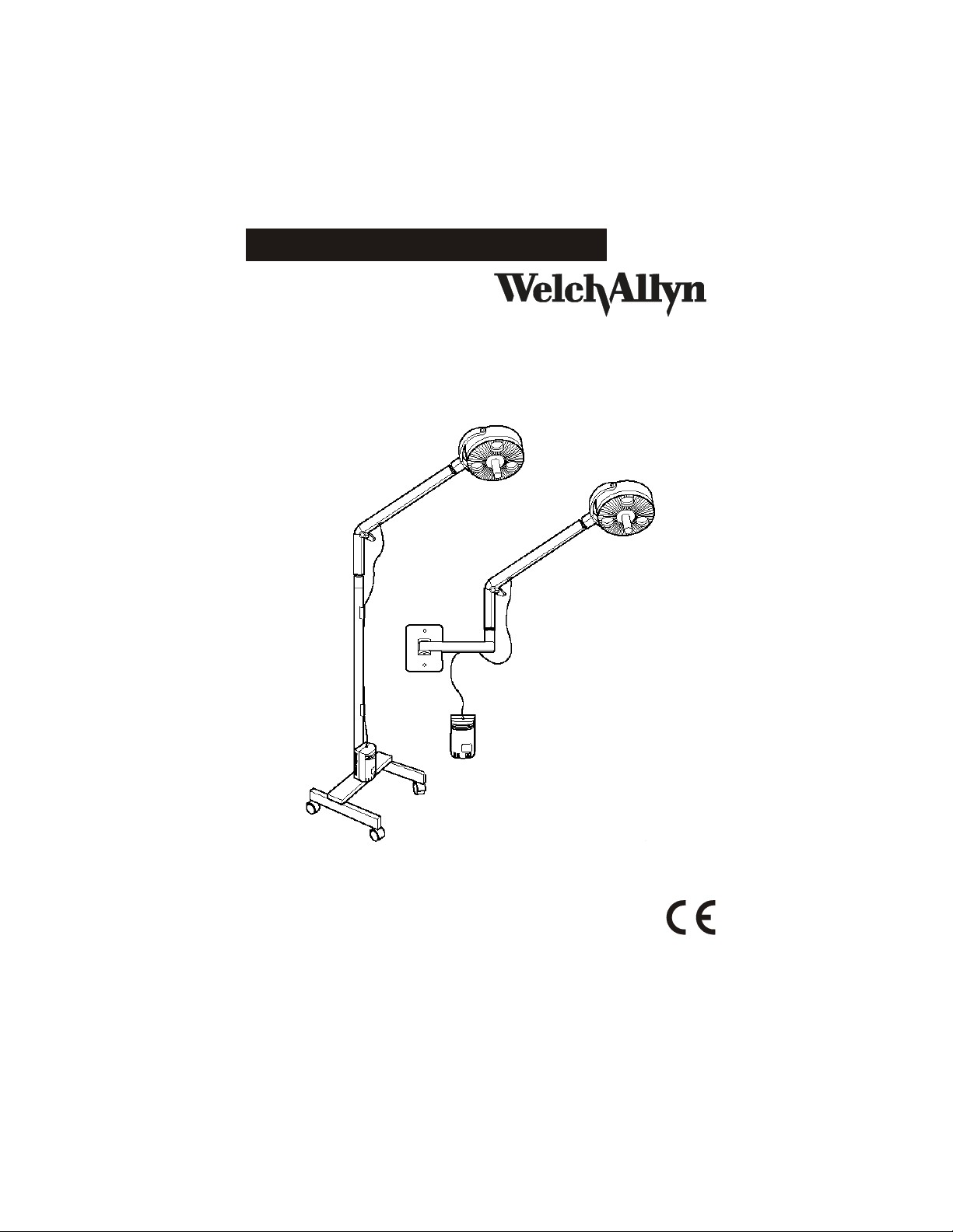
LS200™ Procedure Light
Directions for Use
Page 2

Page 3

LS200™ Procedure Light
Directions for Use
Page 4

ii Welch Allyn LS200 Procedure Light
Copyright 2007, Welch Allyn Inc. All rights are reserved. No one is
permitted to reproduce or duplicate, in any form, this manual or
any part thereof without permission from Welch Allyn.
Welch Allyn assumes no responsibility for any injury to anyone, or
for any illegal or improper use of the product, that may result
from failure to use this product in accordance with the
instructions, cautions, warnings, or statement of intended use
published in this manual.
Welch Allyn
®
is a registered trademark of Welch Allyn, Inc.
Printed in USA
:
USA + 1 315 685 4560
800 535 6663
Canada 800 561 8797 China + 86 216 327 9631
European Call Center + 353 46 906 7790 France + 331 6009 3366
Germany + 49 747 792 7186 Japan + 81 33 219 0071
Latin America + 1 305 669 9003 Netherlands + 31 15 750 5000
Singapore + 65 6419 8100 South Africa + 27 11 777 7555
United Kingdom + 44 207 365 6780 Sweden + 46 85 853 6551
Australia + 61 29 638 3000
800 074 793
Page 5

Contents
1 - Introduction . . . . . . . . . . . . . . . . . . . . . . . . . . . . . . . . . 1
Symbol Descriptions. . . . . . . . . . . . . . . . . . . . . . . . . . . . . . . . . 1
Warning . . . . . . . . . . . . . . . . . . . . . . . . . . . . . . . . . . . . . . . . . . 2
Caution . . . . . . . . . . . . . . . . . . . . . . . . . . . . . . . . . . . . . . . . . . . 3
Components . . . . . . . . . . . . . . . . . . . . . . . . . . . . . . . . . . . . . . . 4
2 - Mounting and Operating Instructions . . . . . . . . . . . . 5
Mounting Instructions. . . . . . . . . . . . . . . . . . . . . . . . . . . . . . . . 5
Mobile Stand Setup . . . . . . . . . . . . . . . . . . . . . . . . . . . . . . 5
Wall Mount Set-up . . . . . . . . . . . . . . . . . . . . . . . . . . . . . . . 7
Mounting The Transformer. . . . . . . . . . . . . . . . . . . . . . . . 11
Operating Instructions . . . . . . . . . . . . . . . . . . . . . . . . . . . . . . 13
Transport For Mobile Stand Unit. . . . . . . . . . . . . . . . . . . . 13
Arm Adjustment . . . . . . . . . . . . . . . . . . . . . . . . . . . . . . . . 14
iii
3 - Maintenance . . . . . . . . . . . . . . . . . . . . . . . . . . . . . . . 15
Troubleshooting . . . . . . . . . . . . . . . . . . . . . . . . . . . . . . . . . . . 16
Cleaning . . . . . . . . . . . . . . . . . . . . . . . . . . . . . . . . . . . . . . . . . 18
Lamp Replacement. . . . . . . . . . . . . . . . . . . . . . . . . . . . . . . . . 19
Fuse Replacement . . . . . . . . . . . . . . . . . . . . . . . . . . . . . . . . . 22
4 - Specifications . . . . . . . . . . . . . . . . . . . . . . . . . . . . . . 23
Electrical Specifications . . . . . . . . . . . . . . . . . . . . . . . . . . . . . 23
Agency Approvals . . . . . . . . . . . . . . . . . . . . . . . . . . . . . . . . . . 24
Key Measurements . . . . . . . . . . . . . . . . . . . . . . . . . . . . . . . . 25
Page 6

iv Contents Welch Allyn LS200 Procedure Light
Operating Environment. . . . . . . . . . . . . . . . . . . . . . . . . . . . . . 26
Warranty . . . . . . . . . . . . . . . . . . . . . . . . . . . . . . . . . . . . . 27
Page 7
1
Introduction
Thank you for purchasing the Welch Allyn® LS200™ Procedure
Light, designed by a leading worldwide manufacturer of
illuminated diagnostic instrumentation. By following the use and
care guidelines given in this manual, you will be rewarded with
years of dependable, trouble-free service from your new LS200
Procedure Light. Read these instructions thoroughly before use.
Symbol Descriptions
Hazard or Warning
Attention, Caution: Consult user’s manual for
more information.
1
Hot Surface
Page 8

2 Chapter 1 Introduction Welch Allyn LS200 Procedure Light
Warning
A warning statement in this manual identifies a condition or
practice, which, if not corrected or discontinued immediately,
could lead to patient injury, illness, or death.
WARNING All users of this procedure light should be
thoroughly trained in the medical procedures appropriate
to the equipment. Furthermore, they should read and
understand the instructions for all other equipment used
in conjunction with the LS200 Procedure Light.
WARNING Lamps are extremely bright. DO NOT stare
directly into lamps when lit.
WARNING DO NOT position luminaire in the upward
direction with the lamps on.
WARNING Risk of explosion if used in the presence of
flammable anesthetics.
WARNING The bezel in front of the lamps may be hot.
Page 9

Directions for Use Chapter 1 Introduction 3
Caution
A caution statement in this manual identifies a condition or
practice which, if not corrected or discontinued immediately,
could lead to equipment failure, equipment damage, or data loss.
Caution Remove power cord from electrical outlet and
allow lamps to cool before replacing (replace with Welch
Allyn Lamp #06400 only). Accessible metal parts of this
unit are electrically isolated from the grounding
conductor of the supply cord. If grounding of the
accessible parts is considered necessary, a separate
grounding lead should be employed.
Caution To reduce the risk of electric shock, do not
disassemble unit. Refer servicing to qualified service
personnel.
Caution Operation at closer than 12"
(30.5 cm) for extended periods may result
in erythema. The designed working
distance is 24" (60 cm).
Caution The switch on luminaire is NOT a mains
switch. Transformer energizes when the light is plugged
to mains.
Page 10
4 Chapter 1 Introduction Welch Allyn LS200 Procedure Light
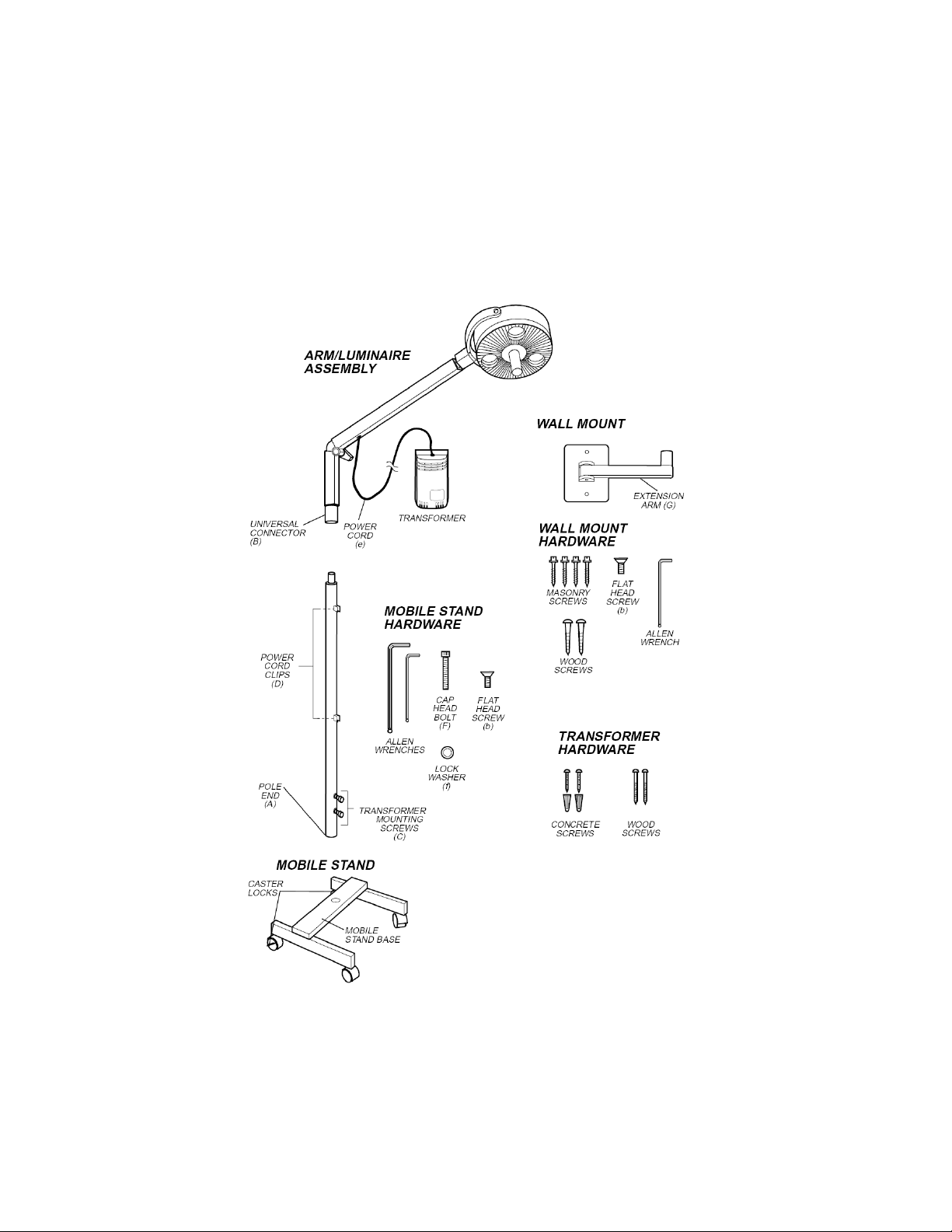
Components
Page 11

Mounting and Operating
2
Instructions
Mounting Instructions
Mobile Stand Setup
1. Remove stand base, pole and hardware kit from boxes.
2. Place stand base on floor with casters down and lock casters.
3. Insert pole end (A) into hole in base of mobile stand.
4. Rotate pole until it aligns with pin and drops into place.
5. Insert cap-head bolt (F) with lock washer (f) through stand
cross member into pole and tighten with 1/4" Allen wrench.
5
6. Carefully remove LS200 arm/luminaire assembly from box.
Hook transformer onto the factory installed mounting screws
(C) on the pole and slide down until secure.
7. Place arm/luminaire assembly on pole by sliding universal
connector (B) onto top end of the pole and align screw holes.
8. Insert 0.5" (13mm) flathead screw (b) into hole on side of
universal connector and tighten with 5/32" Allen wrench.
9. Push power cord attached to transformer into power cord
clips (D) on pole, ensuring enough slack for full range of arm
motion.
10. Attach power cord (e) to transformer.
11. To lock casters, push down on the tab on the locking casters.
Page 12

6 Chapter 2 Mounting and Operating Instructions Welch Allyn LS200 Procedure Light
Before moving the LS200 Procedure Light, see “Transport For
Mobile Stand Unit” on page 13.
Caster locks
Align pin in mobile stand with pole end
Page 13

Directions for Use Chapter 2 Mounting and Operating Instructions 7
Wall Mount Set-up
Caution DO NOT mount into sheetrock. Mount the
LS200 Procedure Light Arm into a wall stud.
The LS200 Procedure Light arm is designed not to go beyond 90°
and the working distance is 24" (60cm). To ensure proper
placement on the wall, locate the top edge of the wall plate 4"
(10cm) above the working surface.
Note
To mount to a wall stud:
1. Remove wall mount assembly and hardware kit from box.
2. Select mounting location on a stud in the wall that is within 8'
3. Using wall plate as a template, place on selected location on
4. Remove wall plate and drill pilot holes using 0.12" (3mm) drill
Use a carpenter’s level to ensure precise, drift-free
movement of the wall plate.
(2.4m) of electrical outlet.
wall, level plate and mark both holes.
bit.
Page 14

8 Chapter 2 Mounting and Operating Instructions Welch Allyn LS200 Procedure Light
5. Place wall plate
on wall and drive
top 1.5" (3.8cm)
wood screw
halfway into
wood stud.
6. Align wall plate
using a level and
secure at bottom
with 1.5" (3.8cm)
wood screw.
7. Tighten top wood
screw.
8. Prepare for transformer mounting by following “Mounting The
Transformer” on page 11 instructions through step 4.
9. Carefully remove LS200 arm/luminaire assembly from box.
Complete transformer mounting according to steps 5 and 6 of
instructions on page 11.
10. Place arm/luminaire assembly on
extension arm by sliding universal
connector (B) onto extension arm
(G) and aligning screw holes.
11. Insert 0.5" (13mm) flathead
screw (b) into hole on side of
universal connector and tighten.
Move arm up and down to check
that mounting is secure.
12. Push cord into clips in underside
of extension arm.
Page 15

Directions for Use Chapter 2 Mounting and Operating Instructions 9
To mount to a concrete or brick wall:
Caution DO NOT use the center two holes in the wall
plate for concrete walls. Additional holes must be drilled
for masonry surface mounting to assure durable
attachment.
1. Remove wall mount assembly and hardware kit from box.
2. Drill holes in wall plate:
a. Place the wall plate flat on a wooden surface.
b. Mark four holes on wall plate 1" (2.5cm) from each edge in
corners of plate.
c. Use a center punch to start holes.
d. Drill four holes using a 13/64" (5.1mm) drill bit
3. Select mounting location on wall that is within 8' (2.4m) of
electrical outlet.
4. Using wall plate as a template, place on selected location on
wall and mark upper-left hole.
5. Remove wall plate and use a center punch to start hole.
6. Using a hammer drill and 5/32" (4mm) masonry drill bit, drill
hole to a minimum of 1.5" (4cm) deep.
Page 16

10 Chapter 2 Mounting and Operating Instructions Welch Allyn LS200 Procedure Light
7. Place wall plate on wall and drive 1.25" (3.2cm) masonry
screw halfway into the wall.
8. Align wall plate using a level and secure by tightening screw.
9. Punch the next three holes with wall plate in place.
10. Drill remaining holes.
11. Fasten wall plate with three remaining screws.
12.Prepare for transformer mounting by following “Mounting The
Transformer” on page 11 instructions through step 4.
13.Carefully remove LS200 arm/luminaire assembly from box.
Complete transformer mounting by following steps 5 & 6 of
instructions on page 11.
Page 17

Directions for Use Chapter 2 Mounting and Operating Instructions 11
14.Place arm/luminaire assembly on extension arm by sliding
universal connector (B) onto extension arm (G) and aligning
screw holes.
15.Insert 0.5" (13mm) flathead screw (b) into hole on side of
universal connector and tighten. Move arm up and down to
check that mounting is secure.
16.Push cord into clips in underside of extension arm.
Mounting The Transformer
1. Select proper mounting hardware from hardware kit in the
LS200 mounting option box: Choose 1" (2.5cm) wood screws
for mounting into wood stud and 1" (2.5cm) sheet metal
screws and plastic anchors for concrete or brick.
2. Select a location for the transformer that is within 8' (2.4m) of
an electrical outlet and within 1.5' (0.5m) of the wall mount
plate to allow enough slack for full range of arm motion.
Page 18

12 Chapter 2 Mounting and Operating Instructions Welch Allyn LS200 Procedure Light
3. Using the template indicators on left side of this page (3 1/8"
[8cm] on center), mark the location for drill holes on the wall.
Make sure they are vertical.
3 - 1/8”
8cm
For wooden walls:
No pilot hole is needed. Use 1.5" 3.8cm) wood screws
from transformer hardware kit.
For concrete walls:
Using a hammer drill and 3/16" (2.3mm) masonry drill bit,
drill holes for plastic anchors to a minimum of 1" (2.5cm)
deep. Tap in plastic anchors from transformer hardware kit
until flush.
Page 19

Directions for Use Chapter 2 Mounting and Operating Instructions 13
4. Drive screws into the wall, allowing screw heads to protrude
11/32"(2.3mm).
5. Mount transformer by fitting round holes in the back of
transformer over mounting screws on wall, then slide
downward until secure.
6. Attach power cord to transformer.
Operating Instructions
Transport For Mobile Stand Unit
1. To prevent the light from tipping, position arm at a 45° angle
or greater, when rolling the LS200 to a new place.
2. Center arm in range of motion.
3. Unlock casters by lifting up on the tabs and hold unit at top of
pole while moving it.
Page 20

14 Chapter 2 Mounting and Operating Instructions Welch Allyn LS200 Procedure Light
Arm Adjustment
The LS200 Procedure Light has been designed to allow the user
to adjust the amount of resistance at the joints of the arm. The
main joint features a large knob for easy adjustment of this key
joint. Turn knob to achieve required tension.
Note
The top and lower joints have been preadjusted at Welch Allyn.
Should further adjustment be necessary, the joint resistance can
be increased or decreased by using a screwdriver to adjust the
set screws at point (A) or (B).
There is no need to adjust knob for every use. The set
tension will be maintained over multiple movements.
NEVER completely unscrew large knob.
Page 21

3
Maintenance
For minor trouble, see “Troubleshooting” on page 16 for possible
causes and corrective action. Only qualified personnel should
make electrical inspections of the LS200 Procedure Light
Repair: To locate qualified service personnel, contact your local,
authorized Welch Allyn distributor, or contact Welch Allyn directly
at 800-535-6663.
15
Page 22

16 Chapter 3 Maintenance Welch Allyn LS200 Procedure Light
Troubleshooting
Trouble Possible Cause(s) Corrective Action
When switch is activated
the light does not turn on
There has been a change
in spot quality or a
decrease in light intensity
Power cord is loose Check connection at wall
A fuse is blown Check fuse. Glass tube will
No power at wall outlet Try another outlet.
Power cord is damaged. Order replacement cord from
Lamp is blown Replace lamp. (See “Lamp
Lamp is not inserted in
socket properly.
Bezel on front of
luminaire was not aligned
properly.
Dirt or dust on bezel or on
the glass filters behind
the bezel.
outlet and at power supply
be blackened if a fuse is
blown. Replace if blown (See
“Fuse Replacement” on
page 22.).
Welch Allyn
Replacement” on page 19.)
Check lamps to ensure they
were properly installed. (See
“Lamp Replacement” on
page 19.)
Make certain the clear
“windows” are lined up with
lamps. (See “Lamp
Replacement” on page 19.)
Clean if necessary. (See
“Cleaning” on page 18.)
Page 23

Directions for Use Chapter 3 Maintenance 17
Trouble Possible Cause(s) Corrective Action
It’s difficult to move the
luminaire, the joints are
stiff.
The set-screw at the
connection at top of arm
and luminaire is too tight.
The arm knob at arm joint
is too tight.
The set-screw in the joint
at the bottom of the arm
is too tight.
Loosen set screw (A). (See
“Lamp Replacement” on
page 19.)
Loosen knob.
Loosen set screw (B). (See
“Lamp Replacement” on
page 19.).
Page 24

18 Chapter 3 Maintenance Welch Allyn LS200 Procedure Light
Cleaning
Caution Cleaning and disinfection should comply with
local authorities responsible for hygiene and disinfection.
Caution Do not to allow solution to drip into luminaire.
Caution DO NOT spray solution directly into joints.
Caution DO NOT sterilize any part of the unit.
Caution DO NOT immerse any part of the unit in
cleaning solutions.
Turn power switch to the OFF position and unplug the power
cord from the electrical outlet prior to cleaning.
You can wipe the entire unit down using a cloth dampened
slightly with a mild solution of detergent and water or glass
cleaner. Do not to allow the plug prongs to get wet. Wipe the unit
dry with a clean, dry cloth.
DO NOT plug the LS200 Procedure Light into the electrical outlet
until the unit is thoroughly dry.
Page 25

Directions for Use Chapter 3 Maintenance 19
Lamp Replacement
WARNING The lamps operate at high temperatures.
DO NOT attempt to replace lamps while they are hot.
Wait until the lamps are cool. Lamps may shatter under
pressure, handle with care. Replace with Welch Allyn
lamp #06400 only.
1. Turn power switch to OFF position and unplug the power cord
from the electrical outlet.
2. Rotate luminaire so that the bezel and handle are facing you
(see A).
3. Turn handle counterclockwise to unscrew (see B). Remove
handle and carefully slide bezel out and allow to rest on wire
tether (see C).
Note
There are (3) color correction filters visible on the bezel
assy once it is removed. These filters also have heat
reduction properties. Do not remove.
Page 26

20 Chapter 3 Maintenance Welch Allyn LS200 Procedure Light
4. Locate release lever on lamp holder and push downward (see
D).
5. Grasp expired lamp by its base with two fingers and slide out
of lamp holder (see E).
6. Return release lever to upward position (see F).
7. Remove Welch Allyn Replacement Lamp #06400 from its
package.
8. Grasp replacement lamp between your two forefingers (see
G).
Note
Try not to touch the inside of reflector—dirt or oil can
cause reduced light output. Clean according to
instructions on page 18, if necessary.
Page 27

Directions for Use Chapter 3 Maintenance 21
9. Carefully slide the lamp into the lamp holder with two fingers,
making sure the two pins on the base of the lamp slide into
the socket and the reflector slides under the spring (see H).
10. To assure proper placement in socket, gently push lamp into
socket until completely seated and snap into place (see I).
11. Replace bezel. Be certain to align the three smooth
“windows” in bezel with lamps and tabs on edge of bezel
with grooves in white housing (see J).
12.Replace handle and rotate clockwise until secure (see J).
Page 28

22 Chapter 3 Maintenance Welch Allyn LS200 Procedure Light
Fuse Replacement
There are two replaceable fuses located in the fuse drawer of the
transformer housing. If either one of these blows, the unit will
not light. Replace only with Welch Allyn part number
236706-3907 for model 44200 or 236706-3114 for models 44202,
44204 and 44206.
1. Turn the power switch to the OFF position and unplug the
power cord from the electrical outlet and transformer.
2. Using a small (1/8") screwdriver, remove the fuse drawer (a)
from the transformer housing by releasing the spring loaded
snap connection (b) on both sides of the component.
3. Pull out fuse drawer.
4. Remove and replace the blown fuse(s). There is no required
orientation of the fuses.
5. Reinsert the drawer by pressing it into the connector until it
snaps into place.
Page 29

4
Specifications
Electrical Specifications
Wiring Diagram:
A HOSPITAL GRADE POWER CORD D ON-OFF SWITCH
B FUSES E LAMPS
C TRANSFORMER - STEP DOWN,
ISOLATED
23
Input Model 44200: 120 Vac, 60 Hz 0.70 A
Output 12.0 Vac @ 5.0 A (three 20-watt lamps)
(U.S.A./Canada/South America/Japan)
Model 44202: 230 Vac, 50 Hz 0.35 A
(Europe, except United Kingdom)
Models 44204, 44206:240 Vac, 50 Hz 0.35 A
(Australia, UK)
Page 30

24 Chapter 4 Specifications Welch Allyn LS200 Procedure Light
Leakage Current Less than 50 µA from any metal part
Fuses User replaceable, both line and neutral.
Models 44202, 44204, 44206: T500 mA, L250V time lag
Agency Approvals
Model 44200 Conforms to: UL60601-1
Models 44202,
44204, 44206
The CE mark indicates this product has been tested to, and
conforms with, the provisions noted in both the 89/336/EEC
Electromagnetic Compatibility Directive and the 73/23/EEC
Model 44200: 1A, 250 V slow-blow
(slow-blow), low breaking capacity
Certified to: CAN/CSA 22.2 No. 60601-1
IEC 60601-1
Low Voltage Directive.
European Contact for Regulatory Compliance:
European Regulatory Manager
Welch Allyn Ltd., Navan Business Park
Dublin Road, Navan, County Meath
Republic of Ireland
Tel: +353 46 90 67700 Fax: +353 46 90 67755
Page 31

Directions for Use Chapter 4 Specifications 25
Key Measurements
Illumination Intensity: 2,500 foot-candles average light output (21,000 lux
average) at 24" (60cm)
Working Distance: 24" (60cm)
Depth of Field: 12" (30cm) total, ±6" (15cm)
Lamps: Dichroic Reflector, 3,000 hour average lamp life
Central Illuminance: 9250 lux
Correlated Color Temperature: 3200K
Cord Length Output Cord: 4' (1.2m)
Input Cord (Detachable): 10' (3.0m)
Luminarie Diameter: 9.5" (24cm)
Material: Lexan™ 940 Polycarbonate
Spot Size: 7" (18cm)
Light Field Diameter: 36 cm
Color Rendering Index: 94
Total Irradiance: 52.1 W/m²
Dimensions Arm: 20” (50cm)
Wall to Luminaire Center (90° to wall): 36” (90cm)
Mobile Stand Legs: 16” (40cm) long x 1” (2.5cm) wide x 2”
Mobile Stand Base: 16” (40cm) long x 18” (45cm) wide x 2.5”
Wall/Table Extension Arm: 10” (25cm)
Mobile Stand Height: 46” (1.2m)
(5cm) high
(6cm) high
Page 32

26 Chapter 4 Specifications Welch Allyn LS200 Procedure Light
Operating Environment
For indoor use only.
Ambient (room)
Temperature
Relative Humidity Range 30% to 75%
Atmospheric Pressure
Range
Mode of Operation Continuous
Transport and Storage
Environment
Ambient temperature: -40°C to 70°C
Relative humidity: 10% to 100%
10°C to 40°C
700 hPa to 1060 hPa
Page 33

Warranty
Welch Allyn warrants LS200 Procedure Light, when new, to be
free of defects in material and workmanship and to perform in
accordance with manufacturer's specifications for a period of
three years from the date of purchase from Welch Allyn or its
authorized distributors or agents. Welch Allyn will either repair or
replace any components found to be defective or at variance
from manufacturer's specifications within this time at no cost to
the customer. It shall be the purchaser's responsibility to return
LS200 Procedure Light to Welch Allyn or an authorized
distributor, agent, or service representative. This warranty does
not include breakage or failure due to tampering, misuse,
neglect, accidents, modification, or shipping. This warranty is
also void if the instrument is not used in accordance with
manufacturer's recommendations or if repaired by other than
Welch Allyn or an authorized agent. Purchase date determines
warranty requirements. No other express warranty is given.
27
Page 34

28 Warranty Welch Allyn LS200 Procedure Light
Page 35

Page 36

4341 State Street Road
Skaneateles Falls, NY 13153-0220 U.S.A.
Website: www.welchallyn.com
P.O. Box 220
Telephone: 315-685-4560
FAX: 315-685-3361
Part # 703343 Ver. C Printed in U.S.A.
 Loading...