

Page 1
/&,ðëíí
Exam/Procedure Light
Service Manual
&(
Illumination and
Imaging System
808596
Rev. A
Operating Manual
Page 2

System Symbol Descriptions
Attention. Read Operating Manual for Warnings, Precautions, and
Instructions for Use.
Potential Equalization Stud
Dangerous Voltage: Refer Servicing to Qualified Personnel
Type B Equipment
Warning: Risk of Fire. Replace Fuses as Marked.
Lamp Service
Picture Brightness
i
Page 3
WARNINGS/CAUTIONS
CAUTION: IF THIS IMAGING AND ILLUMINATION SYSTEM IS USED DURING
INVASIVE SURGERY, THE FAILURE OF A COMPONENT WITHIN THE SYSTEM, FOR
EXAMPLE, LOSS OF VISUALIZATION, MAY INDIRECTLY CAUSE RISK TO THE
PATIENT, THEREFORE, IT IS RECOMMENDED TO HAVE ALTERNATIVE MEANS
AVAILABLE.
1. POSSIBLE EXPLOSION HAZARD. Do not use in the presence of
flammable anesthetics.
2. THE TOP COVER OF THIS BOX SHOULD NEVER BE REMOVED.
ELECTRICAL SHOCK HAZARD DUE TO HIGH INTERNAL
VOLTAGE. THERE ARE NO USER SERVICEABLE PARTS INSIDE
THIS IMAGING AND ILLUMINATION SYSTEM, EXCEPT FOR THE
LAMP AND FUSE WHICH ARE ACCESSIBLE THROUGH THE
BOTTOM AND BACK COVER PANELS.
3. PROVIDE VENTILATION TO PREVENT OVERHEATING.
Provide adequate ventilation.
Do not cover or drape imaging and illumination system.
4. Grounding reliability is achieved only when connected to "hospital-use"
or "hospital-grade" receptacle. Inspect electrical plug and cord
routinely. Do not use if damage is discovered.
5. WARNING: T OTAL SYSTEM RISK CURRENT - EXCLUDING THE
PATIENT APPLIED PART (ENDOSCOPE) - SHOULD NOT EXCEED
100 MICROAMPS. AN ISOLATION TRANSFORMER IS REQUIRED
IF TOTAL SYSTEM RISK CURRENT EXCEEDS 100 MICROAMPS
WHEN ACCESSORIES ARE INTERCONNECTED. REFER TO
OPERATING MANUAL FOR RECOMMENDED ISOLATION
TRANSFORMERS AND PROPER MEASURING TECHNIQUES.
6. CAUTION: Always remove camera system from patient before
connecting/disconnecting camera system to imaging and illumination
system.
7. When possible, keep imaging and illumination system out of patient
field. Always remove surgical imaging system from patient field while
connecting/disconnecting camera.
8. Do not sterilize the imaging and illumination system. Refer to
Operating Manual for cleaning instructions.
ii
Page 4

9. This TYPE-B imaging and illumination system is recommended for use
with TYPE-F, floating endoscopes only.
SEE OPERATING MANUAL FOR ADDITIONAL WARNINGS, PRECAUTIONS
AND INSTRUCTIONS FOR USE.
iii
Page 5

LAMP REPLACEMENT
CAUTION: Lamp may be hot. Lamp voltage is 60 volts
section.
, 24 watts. Refer to Lamp Replacement
iv
Page 6

Welch Allyn LCI-200CE Illumination and Imaging System
Page 1
Page 7

Welch Allyn LCI-200CE Illumination and Imaging System
Page 2
Page 8

Contents
System Symbol Descriptions i
Introduction 4
Indications 4
Contraindications 4
Warnings and Precautions 5
System Description 7
Component Description 8
Welch Allyn LCI-200CE Illumination and Imaging System
Power Box 8
Fiber Optic Bundle 11
CCD Camera Head and Cable 13
System Inspection 13
System Set-Up Procedure 13
Lamp Replacement 14
Fuse Replacement 14
Cleaning and Sterilization 15
Compatible Cleaning Methods 15
Instructions for Cleaning 16
Leakage Current Test Set Up 18
Troubleshooting 19
Specifications 22
Equipment Ordering 24
Warranty and Service 25
Page 3
Page 9

Welch Allyn LCI-200CE Illumination and Imaging System
Introduction
The Welch Allyn LCI -200CE Illumination and I maging System is fundamentally different from any other
illumination or video system. In this product, Welch Allyn has combined a compact light source with
a very small remote video camera which can be attached to any number of rigid or flexible scopes. By
engineering both the video and the illumination end of the product Welch Allyn is able to produce a very
small, highly efficient product. Furthermore, by combining the lighting and imaging in a sing le packag e,
Welch Allyn has dramatically decreased the burden of system setup and has eliminated the need for the
system white balance. The result is a compact, affordable lighting and video sy stem for rigid and flexible
endoscopic procedures.
Indications
Use of the Welch Allyn LCI-200CE Illumination and Imaging System is indicated whenever video
imaging is preferred over standard optical eyepiece imaging. The product is designed to provide video
imaging for a wide range of rigid endoscopes as well as flexible endoscopes. The LCI-200CE itself is
not a scope; it merely provides video imaging for any existing scope. For indications of use with each
of thes e rigid and flexible scopes, the user must consult the operating manual for the specific rigid or
flexible scope. The LCI-200CE must only be used with endoscopes that are approved for their indicated
use. This product must only be used by qualified medical personnel.
Contraindications
The use of the Welch Allyn LCI-200CE is contraindicated when a video image is not the preferred
method of endoscopic visualization. For specific contraindications for various rigid and flexible scopes,
the user must consult the operating manual for the particular scope being used.
Page 4
Page 10

Welch Allyn LCI-200CE Illumination and Imaging System
Warnings and Precautions
CAUTION: IF THIS IMAGING AND ILLUMINATION SYSTEM IS USED DURING INVASIVE
SURGERY, THE FAILURE OF A COMPONENT WITHIN THE SYSTEM, FOR EXAMPLE, LOSS
OF VISUALI Z ATION, MAY INDIRECTLY CAUSE RISK TO THE PATIENT, THEREFORE, IT IS
RECOMMENDED TO HAVE ALTERNATIVE MEANS AVAILABLE.
To ensure patient and operator safety, read and understand this manual before using the LCI-200CE.
POSSIBLE EXPLOSION HAZARD. Do not use in the presence of flammable anesthetics.
The top cover of the Power Box should never be removed. ELECTRICAL SHOCK HAZ ARD DUE TO
HIGH INTERNAL VOLTAGE. THERE ARE NO USER SERVICEABLE PARTS INSIDE THE
IMAGING AND ILLUMINATION SYSTEM EXCEPT FOR THE LAMP AND FUSE WHICH ARE
ACCESSIBLE THROUGH THE BOTTOM AND BACK COVER PANEL S. Refer all service to Welch
Allyn.
Provide ventilation to prevent overheating. Do not cover or drape the Power Box. To ensure adequate
airflow be sure to provide a 3 inch distance between the Power Box chassis and any solid objects.
Grounding reliability is achieved only when connected to hospital-use or hospital-grade receptacle.
Inspect electrical plug and cord routinely. Do not use if damage is discovered.
WARNING: TOTAL SYSTEM RISK CURRENT - EXCLUDING THE PATIENT APPLIED PART
(ENDOSCOPE) - SHOULD NOT EXCEED 100 MICROAMPERES. AN ISOLATION
TRANSFORMER IS REQUIRED IF TOTAL SYSTEM RISK CURRENT EXCEEDS 100
MICROAMPERES WHEN ACCESSORI ES ARE CONNECTED. Refer to Leakag e Current Test Setup
section for recommended isolation transformers and proper measuring techniques.
CAUTION: Always remove camera system from patient before connecting/disconnecting Camera Head
to Imaging and Illumination System.
When possible, keep the Imaging and I llumination System out of patient field. Alway s remove the Power
Box from patient field while connecting/disconnecting the Camera Head.
Do not sterilize the Power Box. Refer to Cleaning and Sterilization section for cleaning instructions.
This TYPE B Imaging and Illumination System is recommended for use with TYPE F floating
endoscopes only. This is necessary to meet the requirements of IEC601-2-18 for a TYPE BF system.
Care should be exercised during procedures, such that fluids do not migrate across insulations between
the TYPE B camera head and TYPE F endoscopes.
External equipment, which will be connecte d to sig na l input and signal output parts or other connectors,
shall comply with relevant IEC standard (IEC 601 series for medical electrical equipment). In addition,
all such combinations - systems- shall comply with the standard IEC 601-1-1 (Safety requirements for
medical electrical systems).
Page 5
Page 11

Welch Allyn LCI-200CE Illumination and Imaging System
Any pers on who c onnec ts e xter na l equipme nt to sig na l input a nd sig na l output parts or other connectors
has formed a system and is therefore responsible for the sy stem to comply with the requirements of IEC
601-1-1.
WARNING: Replace fuses as marked. See Fuse Replacement Section.
WARNI N G : T h e h i gh intensi t y ligh t at the fro n t o f t he Power B ox, at the tip of the Fiber Optic Bundle,
and at the tip of the endoscope may give rise to high temperatures. To minimize the risk of injury , avoid
prolonged contact with tissue.
Be sure that the Fiber Optic Bundle and Camera Head are plugged into the Power Box before
turning the power ON.
Do not switch the LCI-200CE system ON and OFF in ra pid succession.
Doing so will dramatically
shorten lamp life. The lamp needs to "cool down" for approximately 10 to 15 seconds between uses; if
the user turns the LCI-200CE from ON to
OFF
and then immediately back ON, the lamp will not start,
and the LAMP SERVICE light will illuminate.
Since the LCI-200CE uses a custom, proprietary Welch Allyn lamp
always have a spare lamp available
for lamp replacement.
Always attach the soaking cap to the camera connector before soaking.
Do not disconnect the Optical Coupler from the Camera Head before soaking
, as this will make it
possible for fogging to occur between the Camera Head and the Optical Coupler.
Do not remove the camera cable from the Power Box during operation.
For best results, the camera
cable should be plugged into the Power Box before the Power Box is turned ON. Although no damage
will occur to the camera or CCD if the connection is made after the power is turned ON, the camera will
temporarily shut down requiring the operator to restart the unit.
Do not store liquids above or on the LCI-200CE.
Do not attempt to service any part of this product except for lamp and fuse replacement.
WARNING: If used during invasive surgery, a spare system should be kept on standby.
Page 6
Page 12

Welch Allyn LCI-200CE Illumination and Imaging System
System Description
The Welch Allyn LCI -200CE uses a proprietary Welch Allyn lamp to provide high quality illumination
and a state-of-the-art SONY camera with HyperHAD to produce a brilliant video image.
The Welch Allyn lamp, covered by several patents, is a miniature arc lamp; it produces the same color
temper atu re i llumination as a high wattage Xenon arc lamp, but generates only a fraction of the heat.
Whereas most Xenon light sources weigh over 25 pounds, the tiny Welch Allyn lamp allows the
Illumina tio n and Imaging systems to be combined in a box weighing less than 5 pounds. The Welch
Allyn lamp produces a virtual "point source" of light, and is specifically designed to couple with a fiber
optic bundle. Light output is modulated based on the needs of the camera.
The camera used in the LCI-200CE is an advanced SONY one-half inch CCD camera. This camera uses
the proprietary HyperHAD microlens architecture, whereby hundreds of thousands of tiny light g athering
lenses sit on top of the pixels on the CCD. These miniature lenses make the CCD extraordinarily
sensitive to light. The SONY also operates in both Auto-Shutter and Fixed-Shutter speed modes,
depending on the light levels required by the camera.
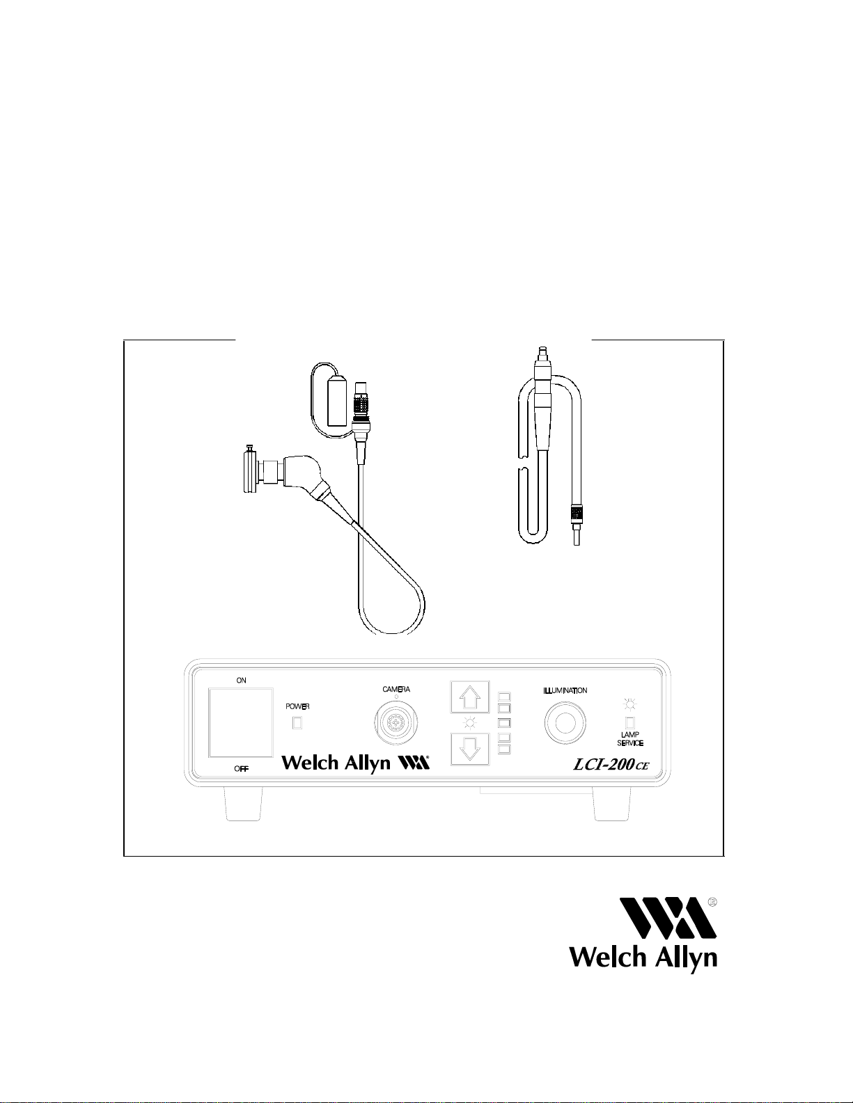
The three major components of the LCI-200CE are shown in the diagram below.
Figure 1: Welch Allyn LCI-200CE
Page 7
Page 13

Welch Allyn LCI-200CE Illumination and Imaging System
Component Description
Component 1. The Power Box houses the lamp, camera processor and power supply. It is described in
more detail below.
Component 2. A Fiber Optic Bundle, using an ACMI adapter on the Power Box end and a universal
adapter on the scope instrument end, is provided. Using any number of adapters, the
Fiber Optic Bundle is attached to any rigid or flexible scope.
Component 3. The remote camera is packaged into an ergonomically designed handpiece, specifically
designed for endoscopic applications. A C-Mount Optical Coupler may be attached to the
remote Camera Head, allowing the camera to adapt to the eyepiece of any rigid or flexible
endoscope.
Power Box
The Welch Allyn LCI -200CE Illumination and I maging System is fundamentally different from any other
system available today , in that it combines the illumination and the video processing in a single, compact
box. Instead of having a separate 300 watt Xenon light source and video processor these two components
are combined in the L CI Power Box. The heart of the Power Box is a Welch Ally n lamp which provides
superior illumination in a package that is a fraction of the size of typical endoscopic light sources. The
light output provided by this lamp is automatically modulated by a mechanical shutter which alters light
output based upon the needs of the camera. The LCI-200CE also houses the video processor for the
camera; the camera used is a state-of-the-art SONY incorporating microlenses, high resolution, and a
continuous, "non-stepping" Auto-Shutter mode for high performing light control that works in tandem
with the mechanical light control shutter.
In addit io n to being smaller, the LCI-200CE Power Box is easier to set up and use than conventional
endoscopic video systems. Since the light source and camera are integrated into a single package, there
is no reason to white balance the LCI-200CE. With the LCI-200CE there are no cables that need to be
connected between a separate light source and video processor. And the LCI-200CE operates exclusively
in automatic light control mode, meaning that there are no adjustments that need to be made for light
control. However, if the user wants to increase the overall picture brightness, this adjustment can be
made on the front panel. Note that the LCI-200CE will still operate in automatic light control mode; only
the overall picture brightness will change.
The LCI-200CE Power Box is driven by a universal switching power supply , which accepts 100-240 V~,
50-60Hz without having to be adjusted. This power supply automatically senses line voltage and makes
the correct adjustments for any line input. The power supply is also Medical Grade and is approved for
medical standards from UL, CSA, TUV, and IEC.
Diagrams of the front and rear panels of the Power Box on the opposite page. Detailed descriptions of
the panels are also provided on the following page.
Page 8
Page 14

Figure 2: Rear Panel
Welch Allyn LCI-200CE Illumination and Imaging System
Figure 3: Front Panel
Rear Panel Front Panel
1. AC Power Input 1. Power Switch
2. Fan Grill 2. Power Indicator
3. 2 Composite Video Outputs, 3. LEMO Connector for Camera Head
BNC Type Connector 4. Picture Brightness Control
4. 2 S-Video Outputs 5. Light Port for Fiber Optic Bundle
5. Potential Equalization Stud 6. Lamp Service Light
6. Fuse Drawer
The single power switch located on the front panel provides power to the lamp, as well as to the camera
system and the attached CCD. The power should only be turned on when the Fiber Optic Bundle and
Camera Head are plugged into the Power Box. When the power is turned to the ON position, the power
LED is illuminated, the lamps take 4-6 seconds to warm up, and the camera is immediately started.
Page 9
Page 15

Welch Allyn LCI-200CE Illumination and Imaging System
In the middle of the front panel is the Camera Connector Port. The Camera Head should be plug g ed into
this connector before the unit is turned ON. The camera connector should be dry of any liquid cleansers
when it is plugged into the Power Box connector. The camera connector should be plugged into the
Power Box before turning the power
ON.
The light port is found on the right side of the front panel. This lig ht port accepts only an ACMI standard
Fiber Optic B undle c onne c tor . Welc h A llyn provides this Fiber Optic Bundle for rigid scopes, and also
provides adapters so that flexible scopes can be plugged directly into the Power Box. See the next section
for fu rth er details on the Fiber Optic Bundle. The Fiber Optic Bundle must be plugged into this port
before
the power is switched
ON.
Next to the light port is a lamp service indicator which illuminates
when the lamp is near the end of its life. The lamp in the Welch Allyn LCI-200CE typically lasts several
hundred hours, based on a 45 minute ON/15 minute
OFF
duty cycle.
Between the light port and the camera port is a brightness control panel. The LCI-200CE allows the user
to set the overall picture brightness of the Camera System by making adjustments on this control panel.
Pressing the UP arrow makes the overall picture brighter, and pushing the
DOWN
arrow makes the
overall picture darker. Note that, no matter what the setting is, the system always works in automatic
light control mode. The user adjustments only change the overall brightness of the picture. The picture
brightness control defaults to the center position when the LCI-200CE is turned on. The automatic lig ht
control functions by the use of a mechanical shutter which modulates the amount of light required for the
camera. T he shutter speed of the camera remains constant and only the amount of light is modulated.
The automatic light control operates in this mechanical-automatic mode in all positions, with the
except ion of the highest picture brightness position. When the user sets the picture brightness to the
maximum position, the shutter opens to allow the maximum amount of light, and the SONY camera
operat es in Auto-Shutter mode. In this way the user is able to choose both picture brightness and
mechan ical vs. electronic light control modes. In most cases the mechanical light control mode is
preferred.
On the rear panel, a power cord connector is found on the far left side. Next to the power connector is
a fan wi th a protective grill and then the video output connectors. Two S-Video connectors and two
composite video connectors are available; any or all of the connectors can be used at one time. Finally,
on the far right of the rear panel is a potential equalization stud which can be used as a safety ground; it
can also be used to ground the system, particularly when there is a risk of video noise caused by
electrosurgery units.
The LCI-200CE complies with the requirements of EN60601-1, EN60601-1-2, IEC 601-2-18, CAN/CSA
601.1 and UL 2601.
"The CE mark on this product indicates it has been tested to and conforms with the provisions noted
within the 89/336/EEC Electromagnetic Compatibility Directive".
Page 10
Page 16

Welch Allyn LCI-200CE Illumination and Imaging System
Fiber Optic Bundle
For rigid endoscopy, the Welch Allyn LCI-200CE Power Box r equir e s a F iber Optic Bundle to carry the
light from the Power Box to the rigid endoscope. Welch Allyn provides a 5mm diameter Fiber Optic
Bundle which is designed specifically for the Power Box. This Fiber Optic Bundle has an ACMI adapter
on the Power Box end and a universal light post at the scope end. Scope Adapters are available for the
universal light post to accommodate all rigid scopes. These adapters screw onto the universal light post.
See diagram below:
Figure 4: Fiber Optic Bundle used with Scope Adapters
When snapping the Fiber Optic Bundle into the Power Box, the user will notice a tight connection. Three
ball detents hold the Fiber Optic bundle in precise alignment with the Welch Allyn lamp. This alignment
is cri tic al t o the performance of the product. Because of this tight alignment,
Fiber Optic Bundle should be used
; if other Fiber Optic Bundles are used, the quality of the
only the Welch Allyn
illumination and the image will be compromised.
WARNING: Inserting the light post end of the fiber optic bundle into the power box may result
in severe damage.
Page 11
Page 17

Welch Allyn LCI-200CE Illumination and Imaging System
Unlike rigid borescopes, which require a separate Fiber Optic Bundle to carry light from the light source
to the scope, most flexible scopes have a Fiber Optic Bundle which runs all the way from the light source
to th e t ip of the scope. In order to accommodate these flexible scopes, Welch Allyn has developed a
number of adapters which convert the fiber optic connector to an ACMI standard. The diagram below
illustrates this with several flexible scopes.
Figure 5: Flexible Scopes with Adapters
These adapters are available from Welch Allyn, and allow any flexible fiberscope to plug directly into
the Welch Allyn LCI-200CE system.
Page 12
Page 18

Welch Allyn LCI-200CE Illumination and Imaging System
CCD Camera Head and Cable
The CCD camera used in the Welch Allyn Illumination and Imaging System is a high performance, 1/2
inch SONY CCD, using Auto-Shutter, HyperHAD, and an automatic color tracking system. The CCD
is op erated in either fixed shutter speed or Auto-Shutter mode, depending on the picture brightness
control setting. HyperHAD technology, developed by SONY, places a tiny light-gathering lens on top
of each pixel, making the CCD over 2 1/2 times more sensitive to light than the conventional CCD. The
CCD is packaged into a very small, ergonomically designed handpiece, and the cable is packaged in a
sturdy but lightweight neoprene cord, under which is a strong, stainless steel braid.
The Camera Head has a standard C-Mount interface, which can accept any C-Mount Optical Coupler.
Welch Allyn provides a fixed focal length, 35mm Optical Coupler with the LCI-200CE. The LCI-200CE
does not require that the screen image occupy a certain percentage of the total screen.
At the other end of the CCD imager head a connector is permanently connected to the cable. This cable
plugs into the front panel of the Power Module. A connector cap is also provided which must be attached
to the connector before cleaning the Camera Head and Cable. The connector should never be wet when
plugged into the Power Box. The connector should be plugged in before the power button is switched
to the ON position.
System Inspection
Prior to us e insp ect the Camera Cable, head, and connectors for signs of wear. Ensure that the lens
system is securely attached to the Camera Head. Likewise, the Fiber Optic Bundle should be inspected
for abnormalities. Be sure that the proper adapters are used on the Fiber Optic Bundle in order to make
a secure connection between the Fiber Optic Bundle and the scope. Finally, before plugging the Camera
Head into the Power Box, check that it is dry and free of rinsing and/or soaking solution.
System Setup Procedure
1. Plug t h e P ower Box into a hospital grade receptacle. Make either the S-Video, the Composite
Video, or both of the connections between the Power Box and a video monitor.
2. For rigid endoscopy, plug the Welch Allyn Fiber Optic Bundle into the Power Box and connect
the proper adapter to the sc ope end of the F ibe r Optic B undle. Atta c h the F iber Optic Bundle to
the proper scope. For flexible endoscopy attach the proper flexible Scope Adapter to the Power
Box end of the flexible scope. Plug the scope and adapter into the Power Box.
3. Plug the Camera Cable connector into the front panel of the Power Box. Attach the scope to the
Optical Coupler.
4. Turn the power to the ON position.
After turning the power ON the lamp will take 4-6 seconds to complete its warm-up routine. At the end
of that time a high intensity white light will appear out of the scope. Since Welch Allyn integrates the
lamp, fiber optics, and video system into a single product family, there is no need to white balance the
system.
The la m p needs to " cool down" for approximately 10-15 seconds between uses. Attempting to restart
a lamp in less than this amount of time will shorten the life of the lamp.
Page 13
Page 19

Welch Allyn LCI-200CE Illumination and Imaging System
Lamp Replacement
The Welch Allyn LCI-200CE uses a proprietary Welch Ally n lamp which typically lasts several hundred
hours when used for one hour procedures.
immediate replacement when needed. USE CAUTION BECAUSE LAMP MAY BE HOT.
replace the lamp, follow the steps below and consult the diagram at the bottom of the page.
1. Unplug the power cord from the Power Box.
2. Remove the lamp door from the bottom of the Power Box using a flathead screwdriver.
3. Disconnect the lamp connector assembly and remove the lamp from the holding spring
assembly.
4. Replace with VA294 Welch Allyn Replacement Lamp only. Pay attention not to touch
the lamp itself, or the interior reflective surface of the lamp, as skin oils on the lamp will
cause premature lamp failure. Handle the lamp by holding the outside of the reflector or
the connector only.
5. Re-connect the lamp to the lamp connector and place the lamp into the spring mechanism.
Be sure that the pin fully engages the slot on the lamp bracket.
6. Replace lamp door and attach securely.
Always have a spare Welch Allyn lamp in stock for
To
The unit will not power up
unless the lamp door is firmly
and securely replaced.
Fuse Replacement
1. Turn the Power Switch
2. Remove the fuses from the Fuse Holder at the A.C. Power Input Receptacle (see Figure 2).
3. If a fuse is blown, replace with a new fuse of the same type. Be sure to check both fuses.
Replacement fuse is a 2.0 Amp, 250 Volt, 5 x 20mm, Type F2AL, which is Welch Allyn's part
number VA303.
OFF
and remove the Power Cord from the Power Box.
4. If the Power Box blows the new fuse, contact Welch Allyn Product Service Group.
Page 14
Page 20

Welch Allyn LCI-200CE Illumination and Imaging System
Cleaning and Sterilization
Careful l y re view the instructions for cleaning and sterilization found in this manual. The first section
highlights compatibility of the L CI-200CE with various cleaning methods, and the next section highlights
instructions for cleaning of each of the components of the LCI-200CE.
Compatible Cleaning Methods
BE SURE TO FOLLOW YOUR INSTITUTION'S SPECIFIC CLEANING AND STERILIZATION
PROCEDURES IN CONSULTATION WITH THIS OPERATING MANUAL. Sterilization is always
recommended for devices coming in contact with the patient; always sterilize rigid and flexible scopes
before use. Note that the LCI-200CE I llumination and Imaging System does not come in patient contact
(it attaches to the proximal end of an endoscope).
1. Power Box (illustrated in Figure 1)
The Power Box should not be sterilized.
cord from the Power Box. The surfaces may be cleaned by wiping with a damp cloth using a mild
detergent.
2. Fiber Optic Bundle and Scope Adapters (illustrated in Figures 1 and 4)
The Fiber Optic Bundle and Scope Adapters are compatible with the following cleaning methods:
- ETO (ethylene oxide) sterilization (see instructions on the following page)
- 2% glutaraldehyde soak (10 hours for sterilization, 30 minutes for disinfection)
- Autoclaving
- Steris
To clean, turn power
OFF
, and disconnect the power
3. Camera Head, Camera Cable, and Optional Optical Coupler (illustrated in Figure 1)
The Camera Head, Camera Cable, and Optical Coupler are compatible with the following
cleaning methods:
- ETO (ethylene oxide) sterilization (see instructions on the following page)
- 2% glutaraldehyde soak (10 hours for sterilization, 30 minutes for disinfection)
- Steris
WARNING: The Camera Head, Ca mera C able, and Optical Couple r should never be autoclaved.
The Camera Head Assembly and Fiber Optic Assembly may also be draped.
Page 15
Page 21

Welch Allyn LCI-200CE Illumination and Imaging System
Instructions for Cleaning
System Disassembly
1. Turn Power Box
OFF
.
2. Disconnect Fiber Optic Bundle from the Power Box. Pull the ACMI adapter straight out.
3. Disconnect Scope Adapter from the Fiber Optic Bundle.
4. Disconnect the Camera Head Cable from the Power Box. Release the LEMO connector by
pulling the shell straight back approximately 0.1 inch. This will release the locking mechanism.
Continue pulling the connector straight back so it disconnects from the Power Box.
5. Immediately screw the Soaking Cap onto the LEMO Connector and secure tightly.
6. The Op tica l Coupler may be disconnected from the Camera Head for cleaning; however, it is
recommended that the coupler be left connected to the Camera Head during cleaning procedures.
This will minimize the chance of condensation forming between the coupler and the Camera
Head when the two pieces are reattached, and will thus reduce the chances of fogg ing during use.
Cleaning/Sterilization
1. Rinse t h e Camera Head and Cable, Optical Coupler, Fiber Optic Bundle, and Scope Adapters
in lukewarm tap water. Use a mild enzymatic detergent to remove any resistant debris.
2. Follow your institutions specific cleaning procedures at all times.
endoscope that is used with the LCI-200CE
. Specific sterilization instructions for the LCI-
Always sterilize the
200CE appear below. To ensure compatibility and prevent damage to the LCI-200CE, consult
the previous section on Compatible Cleaning Methods.
ETO Sterilization (for Camera Head Assembly and Fiber Optic Bundle)
To st erilize the Camera Head, Cable, and Fiber Optic Bundle, the components may be
short cycle ETO cy cled in a temperature of 130+5 degrees F., 60+20% RH for two hours,
followed by a 12 hour aeration at 120+5 degrees F.
Long Soak Sterilization (for Camera Head Assembly and Fiber Optic Bundle)
To st erilize the Camera Head, Cable, and Fiber Optic Bundle, the components may be
soaked in a 2% glutaraldehyde solution for 10 hours. After this period, the components
should be rinsed in sterile water to remove any soaking solution.
Short Soak Disinfection (for Camera Head Assembly and Fiber Optic Bundle)
To disin f e ct the Cam e r a H ead, Cabl e , and Fiber Optic Bundle, the component should be
soaked in a 2% glutaraldehyde solution for 30 minutes. After this period, the components
should be rinsed in sterile water to remove any soaking solution. NOTE: All endoscopes
used with the LCI system should be sterilized, not just disinfected, per the instructions on
the endoscopes.
Page 16
Page 22

Welch Allyn LCI-200CE Illumination and Imaging System
3. The Camera Head, Camera Cable, and Fiber Optic Bundle should be dried with a lint-free, sterile
cloth. The glass window on the Camera Head and Optical Coupler should not be allowed to air
dry as this may lead to fogging.
Before using a Camera Head that has been soaked, the user must ensure that there is no moisture on or
in the LEMO connector. Any moisture that is on the pins of the connector should be dried off g ently with
a lint-free, sterile cloth. If moisture is on the connector when it is connected to the Power Box, the
system may not function properly.
System Reassembly
Be sure to follow your institution's sterility procedures while reassembling the LCI-200CE.
1. Ensure Power Box is turned
OFF.
2. Connect Fiber Optic Bundle to the Power Box. Connect the appropriate scope adapter to the
universal light post at the end of the Fiber Optic Bundle.
3. If applicable, connect and secure the Optical Coupler and endoscope to the Camera Head.
Connect Fiber Optic Bundle to the endoscope.
4. Unscrew the soaking cap on the LEMO connector. Align the orange dot on the top of the LEMO
connect or wi th the orange dot on the Power Box. Gently push the LEMO connector into the
Power Box connector. Ensure that the LEMO shell latches.
WARNING: Because surfaces of this LEMO connector may not be sterile, avoid handling
sterile assemblies after connecting the LEMO connector to the Power Box. Follow your
institution's guidelines for further procedures.
5. Turn Power Box ON and verify that the LCI-200CE functions properly. If picture does not
appear, turn
OFF
power and verify that the LEMO connector is fully seated. If problems persist,
see section on Troubleshooting.
Page 17
Page 23

Welch Allyn LCI-200CE Illumination and Imaging System
Leakage Current Test Setup
When the LCI-200CE camera sy stem is used in conjunction with other video accessories (such as printers
and VC R s) , it may be necessary to measure the leakage current of the entire setup. A typical setup is
shown in Figure 6 below. Using a standard leakage tester, this setup will allow the overall system
leakage current to be measured. An isolation transformer must be used if the leakage current exceeds 100
microamperes, in order to conform with EN60601-1 standards. The maximum allowable leakage current
of the patient applied part (Type F endoscope) is 100 microamperes.
Figure 6: Typical Leakage Current Test Set Up
Page 18
Page 24

Welch Allyn LCI-200CE Illumination and Imaging System
Troubleshooting
Always be sure that the equipment is properly configured and is being used properly before returning any
equipment. Also, try to isolate the problem equipment (Power Box, Camera Head, scope, monitor, VCR)
before returning equipment. Be sure to identify the problem symptom below and try the suggested
corrective action. If, after exhausting these options, the problem persists, contact Welch Allyn (see
Warranty and Service
Symptom: No Picture, Power LED not illuminated, Lamp is not illuminated
- Is Power Box plugged into wall outlet?
- Is Power switch turned ON?
- Is lamp door on bottom of the Power Box secured in place?
- Check fuses.
- Substitute a new power cord.
Symptom: No Picture, Power LED is illuminated, Lamp is illuminated
- Was the Camera Head connected to the Power Box before the power was turned
Connecting the Camera Head to the Power Box while the power is ON causes the camera to shut
down. To correct, turn the power
- Is the monitor plugged into the wall outlet and turned ON?
- Are BNC and S-Video cables connected to the monitor and Power Box? Are the cables
defective? Try substituting new video cables. Trace video cables through the system, ensuring
that they are properly connected through the peripherals and into the monitor.
- Is the monitor set up properly? Is the video connection made to the correct connector on the
monitor? Ensure that the proper video channel is selected on the monitor, and that the brightness
is properly set.
- Are all accessories (VCR, video printer, etc.) turned on and switched to "Line"? Is the VCR
record button ON? Try disconnecting the accessories.
- Is the rod lens scope properly secured to the Optical Coupler?
- Check to ensure that the serial number of the Camera Head is the same as the serial number of
Power Box; if they are not the same number, return unit to your dealer.
section).
OFF
, conne c t t h e C a m e r a Head, wait ten seconds, and restart.
ON?
Symptom: Lamp is OFF, Power LED ON, Lamp Service LED is ON
- Was the lamp able to "cool down" before the power was turned ON? If not, turn the Power Box
OFF
, wait 10 seconds, and turn it back
- If the lamp still does not start eve n af ter be ing allowe d to cool down, replace the lamp assembly
(see Lamp Replacement Section).
- If problem persists with new lamp, return Power Box to Welch Allyn for repair.
Page 19
ON.
Page 25

Welch Allyn LCI-200CE Illumination and Imaging System
Symptom: Picture good, Power LED ON, Lamp is illuminated, Lamp Service LED is ON
- If the serv i c e LED turn s o n a p p roximately 5-10 seconds after initial lamp ignition, then replace
the lamp and verify proper function. I f problem persists, return the unit to Welch Ally n for repair.
- If the service LED turns on approximately 30 seconds to 30 minutes after initial lamp ignition,
then the lamp is near the end of its life. Replace the lamp as soon as possible.
Symptom: Intermittent Video
- Check all video connections: Camera Head to Power Box, Power Box to monitors, etc.
Substitute different video cables. Take the printer or VCR out of the video signal loop.
- Wiggle the connector and cable between the Camera Head and cable, and between the cable and
the Pow e r Box. I f this exa ggerat es the int e rmittent video signal, return the unit to Welch Allyn.
- Check to ensure that the serial number of the Camera Head is the same as the serial number of
Power Box; if they are not the same number, return unit to your dealer.
Symptom: Bad Color in Video Picture
- Have the lamps completely warmed up (10 seconds)?
- Does the lamp need to be replaced?
- Are the color settings on the video monitor properly set? Has the video monitor been calibrated
recently (ie: in the past six months)? Make any necessary adjustments to the monitor or try a new
monitor.
- If a printer or VCR is being used, try taking it out of the video loop.
- Check the video cables being used. Try substituting new video cables.
- Check the Fiber Optic Bundle being used; is it the Welch Allyn Fiber Optic Bundle sold with the
LCI-200CE or is a different bundle being used? The integrity of color can only be guaranteed
when t he Welch Allyn VA295 Fiber Optic Bundle is being used. If the Fiber Optic Bundle
appears to be damaged, replace it with a new VA295 bundle.
- Are the air vents on the Power Box obstructed? If so, move the Power Box to ensure adequate
ventilation.
- Check to ensure that the serial number of the Camera Head is the same as the serial number of
the Power Box; if they are not the same number, return unit to your dealer.
Symptom: Video Interference (especially when used with electrosurgery)
NOTE: A small amount of video interference is normal. I f the interference is objectionable, then
try the following:
- Be sure a hospital grade power cord is being used.
- Be sure that the Power Box is properly grounded.
- Try plugging the electrosurgery unit into a different power outlet on a different circuit.
- Minimize the overlap between the video cable and the electrosurgery cable.
- Using a type F endoscope will help minimize electrosurgery interference.
- Change the picture brightness control on the front panel; the default (center) position should cause
the least amount of video interference.
- Ensure that all video equipment (monitor, slave monitor, VCR, etc.) is plugged into one wall
outlet.
Page 20
Page 26

Welch Allyn LCI-200CE Illumination and Imaging System
Symptom: Blurry or "Soft" Image; Image not Sharp
- Adjust settings on monitor or printer, starting with the controls in the reset position.
- Check the focus on the Optical Coupler.
- Remove the endoscope from the Optical Coupler and look through the endoscope. If the image
appears blurred, the endoscope needs repair. Return the scope to the proper manufacturer.
- Check to make sure that there is no moisture between the endoscope and the coupler. If moisture
is present, dry it off with a soft cloth.
- Th ere should never be moisture between the Camera Head and the coupler, as long as the two
components are kept together when they are soaking. To prevent fogging, the coupler should
never be removed from the Camera Head prior to or immediately after soaking.
- Check for fingerprints on all lens surfaces.
- Does camera head and power box serial number match?
Symptom: Spots on Image
- Check the optical surface between the scope and Optical Coupler.
Symptom: Grainy Image
- Is enough light being delivered to the tip of the scope? Does the lamp need to be replaced?
- Is the Fiber Optic Bundle damaged so that not enough light is being delivered? Try new lamps
and a new Fiber Optic Bundle.
- Adjust monitor and/or printer settings, starting with controls in the reset position.
- Ensure the camera cable is fully plugged into the Power Box.
- Remove all accessories from the setup and verify that the image is acceptable using only the L CI 200CE and the monitor.
- Increase the picture brightness setting to a higher position.
Symptom: Dark Picture
- Adjust the monitor and/or printer, starting with the controls in the reset position.
- Increase the picture brightness setting to a higher position.
- Check to verify that the lamp is functioning.
- Check to verify that the Fiber Optic Bundle is not damaged, and that it is still transmitting an
adequate amount of light.
- Remove all accessories from the setup and verify that the imag e is acceptable using only the LCI200CE and the monitor.
- Does camera head and power box serial number match?
Page 21
Page 27

Specifications
Power Supply
100-240V~, 50-60 Hz, automatically adjusted
Input Current: 1.0 - 0.5 Amp
Dimensions
9.25 inches wide x 8.125 inches deep x 2.375 inches high
Less than 5 pounds
Outputs
2 Y/C S-Video Type
2 Composite BNC type, 1.0V p-p 75 ohms
Illumination System
Proprietary Welch Allyn Arc Lamp
Color Temperature 5500 degrees K
Lamp: 60 Volts , 24 watts
Lamp Life averages several hundred hours when used for a 45 minute ON/15 minute OFF duty
cycle. Average lamp life decreases substantially when shorter duty times are used.
Welch Allyn LCI-200CE Illumination and Imaging System
w
Shutter System
Mechanical: Motor driven shutter
Electrical: Infinitely variable, no-step Auto-Shutter
Image Device
1/2" SONY Interline Transfer CCD with HyperHAD
756 x 581 Total Pixels (PAL)
Cable Length 10 feet
Scanning System
2:1 Interlaced, 625 lines, 25 frames/sec (PAL)
Horizontal Resolution
Greater than 470 lines
Fiber Optic Bundle Interface
Power Box Side: ACMI
Scope Side: Universal
Bundle Length: 7.5 feet
Approvals
UL-2601, EN60601-1, IEC601-1, IEC601-2-18, and CAN/CSA 601.1
89/336/EEC Electromagnetic Compatibility Directive
Page 22
Page 28

Equipment Classification
Power Box - Class I, Type B
Camera Head - IPX7, Type B
When used with Type F endoscope, complete system is classified Type BF
Environmental Conditions
Storage
Humidity: 10 to 100% (condensating)
Temperature: -20 deg. C to +60 deg. C
Use
Humidity: 10 to 95% (non-condensating)
Temperature: +5 deg. C to +40 deg. C
Fuses
250V, 2.0 amps, 5 x 20mm, Type F2AL
Patents
5,144,201; 5,083,059; 5,138,228; 5,117,154; others pending
Welch Allyn LCI-200CE Illumination and Imaging System
Page 23
Page 29

Equipment Order Numbers
LCI-200CEP
VA294
VA295
VA296
VA297
VA298
VA299
VA300
VA350
VA301
VA370
VA303
VA285
VA177
VA284
VA284-2
VA316
VA360
VA361
Welch Allyn LCI-200CE Camera System, PAL
Replacement Lamp, LCI
7.5 foot Fiber Optic Bundle, LCI
Storz Scope Adapter, LCI
Wolf Scope Adapter, LCI
ACMI Scope Adapter, LCI
Replacement 35mm Optical Coupler
Replacement 45mm Optical Coupler
Replacement 28mm Optical Coupler
Carrying Case
LCI-200CE Operating Manual
Replacement Fuse, 2.0A, 250V, 5x20mm
S-Video Cable, 12 feet
Composite Cable, 10 feet
US Power Cord
International Power Cord
LCI-100/200 Service Manual
Isolation Transformer 120V 4.6 Amps
Isolation Transformer 120V 8.4 Amps
Welch Allyn LCI-200CE Illumination and Imaging System
Page 24
Page 30

Welch Allyn LCI-200CE Illumination and Imaging System
Warranty and Service
Welch Allyn warrants the LCI-200CE, when new, to be free of defects in material and workmanship
and to perform in accordance with manufacturer's specifications when subject to normal use and service
for a p e r i o d of one year from the date of purchase from Welch Allyn or an authorized agent. Welch
Allyn will either repair or replace any components found to be defective or at variance from
manufact urer's specifications within this time at no cost to the customer. It shall be the purchaser's
responsibility to return the instrument directly to the authorized distributor, agent, or service
representative.
This warranty does not cover the HI-Lux Lamp or breakage or failure due to tampering, misuse,
neglect, accidents, improper installation, modification, shipping, or to improper maintenance, service,
and cl e aning procedures. This warranty is also void if the instrument is not used in accordance with
manufacturer's recommendations or if required or serviced by other than Welch allyn or an authorized
agent. Purchase date determines warranty requirements. No other express or implied warranty is
given.
Service Manuals are available from W elch Allyn. For Service assistance or questions regarding this
warranty, please contact Welch Allyn at:
US, Europe, and Asia Latin America
Welch Allyn, Imaging Products Division MD International
4619 Jordan Road 7324 S.W. 48th Street
Skaneateles Falls, NY 13153 Miami, FL 33155
Telephone: (315) 685-4108 Telephone: (305) 669-9003
Fax: (315) 685-2920 Fax: (305) 669-8951
Europe Asia
Welch Allyn GmbH Welch Allyn Hong Kong
Zollerstrasse 2-4 10/F Tung Sun Commercial Ctr.
D-72417 Jungingen 194-200 Lockhart Rd
Federal Republic of Germany Wanchai
Telephone: 011-49-74779-27273 Hong Kong
Fax: 011-49-74779-27293 Telephone: 011-852-2511- 3050
Fax: 011-852-2511- 3557
Australia
Welch Allyn Australia Pty Limited
ACN 062 931 462
Ground Floor
18-20 Orion Road
Lane Cove
NSW 2066
Australia
Telephone: 011-612-418-3155
Fax: 011-612-418-3650
Page 25
 Loading...