

Page 1

LC101 CO2 Module
OEM Implementation Manual
Page 2

P
W
W
LC101 CO
Cop yright © 2002 by Welch Allyn OEM Technologies. Welch Allyn
Module OEM Implementation Man ual
2
®
is a registered tr ademark,
and Pryon™ is a trademark of Welch Allyn, Inc. Welch Allyn, Inc. is protected under various
patents and patents pending. Welch Allyn OEM Technologies is a division of Welch Allyn, Inc.
Disc laimers: Welch Allyn OEM Technologies cautions the reader of this manual:
• This manual may be wholly or partially subject to change without notice.
• All rights are reserved. No one is permitted to reproduce or duplicate, in any form, the
whole or part of this manual without permission from Welch Allyn OEM Technologies.
For inf ormation concerning this document, contact:
elch Allyn OEM Technologies
8500 SW Creekside Place
Beaverton, OR 97008-7107 U.S.A
(503) 530-7900 • Fax: (503) 526-4901
PN 000.91161 Rev. 1, September, 2002
age 2
Confi dential
elch Allyn OEM T echnologies
Page 3

W
C
P
T
LC101 CO
Module OEM Implementation Man ual
2
able of Contents
Section 1
Functional Description . . . . . . . . . . . . . . . . . . . . . . . . . . . . . . . . . . . . . . . . . . . . . . . . 7
Introduction . . . . . . . . . . . . . . . . . . . . . . . . . . . . . . . . . . . . . . . . . . . . . . . . . . . . . . . . . . . . . . . . . . . . . . . . 7
Intended Use . . . . . . . . . . . . . . . . . . . . . . . . . . . . . . . . . . . . . . . . . . . . . . . . . . . . . . . . . . . . . . . . 7
Terminology. . . . . . . . . . . . . . . . . . . . . . . . . . . . . . . . . . . . . . . . . . . . . . . . . . . . . . . . . . . . . . . . . . . . . . . . 8
Mainstream vs. Sidestream . . . . . . . . . . . . . . . . . . . . . . . . . . . . . . . . . . . . . . . . . . . . . . . . . . . . . 8
Measuring Principle . . . . . . . . . . . . . . . . . . . . . . . . . . . . . . . . . . . . . . . . . . . . . . . . . . . . . . . . . . . . . . . . . . 8
Measurement Calculation. . . . . . . . . . . . . . . . . . . . . . . . . . . . . . . . . . . . . . . . . . . . . . . . . . . . . . . 9
Measurement Compensation . . . . . . . . . . . . . . . . . . . . . . . . . . . . . . . . . . . . . . . . . . . . . . . . . . . 10
Hardware Components . . . . . . . . . . . . . . . . . . . . . . . . . . . . . . . . . . . . . . . . . . . . . . . . . . . . . . . . . . . . . . 11
LC101 Main Board . . . . . . . . . . . . . . . . . . . . . . . . . . . . . . . . . . . . . . . . . . . . . . . . . . . . . . . . . . . 11
Sidestream Components . . . . . . . . . . . . . . . . . . . . . . . . . . . . . . . . . . . . . . . . . . . . . . . . . . . . . . 13
Section 2
LC101 Module Interface. . . . . . . . . . . . . . . . . . . . . . . . . . . . . . . . . . . . . . . . . . . . . . . 15
Power Requirements . . . . . . . . . . . . . . . . . . . . . . . . . . . . . . . . . . . . . . . . . . . . . . . . . . . . . . . . . . . . . . . . 15
LC101 Main Board. . . . . . . . . . . . . . . . . . . . . . . . . . . . . . . . . . . . . . . . . . . . . . . . . . . . . . . . . . . . . . . . . . 15
LC101 Module Interface Connector. . . . . . . . . . . . . . . . . . . . . . . . . . . . . . . . . . . . . . . . . . . . . . . . . . . . . 16
Watertrap Switch Connection . . . . . . . . . . . . . . . . . . . . . . . . . . . . . . . . . . . . . . . . . . . . . . . . . . . . . . . . . 16
Pump . . . . . . . . . . . . . . . . . . . . . . . . . . . . . . . . . . . . . . . . . . . . . . . . . . . . . . . . . . . . . . . . . . . . . . . . . . . . 16
Watertrap Receiver . . . . . . . . . . . . . . . . . . . . . . . . . . . . . . . . . . . . . . . . . . . . . . . . . . . . . . . . . . . . . . . . . 16
Watertrap Receiver Switch . . . . . . . . . . . . . . . . . . . . . . . . . . . . . . . . . . . . . . . . . . . . . . . . . . . . . . . . . . . 17
Exhaust Tubing . . . . . . . . . . . . . . . . . . . . . . . . . . . . . . . . . . . . . . . . . . . . . . . . . . . . . . . . . . . . . . . . . . . . 17
Section 3
LC101 Calibration . . . . . . . . . . . . . . . . . . . . . . . . . . . . . . . . . . . . . . . . . . . . . . . . . . . 19
Zero Calibration . . . . . . . . . . . . . . . . . . . . . . . . . . . . . . . . . . . . . . . . . . . . . . . . . . . . . . . . . . . . . . . . . . . . 19
Zero Calibration Procedure . . . . . . . . . . . . . . . . . . . . . . . . . . . . . . . . . . . . . . . . . . . . . . . . . . . . 20
Two-Point User Calibration . . . . . . . . . . . . . . . . . . . . . . . . . . . . . . . . . . . . . . . . . . . . . . . . . . . . . . . . . . . 21
Two-Point User Calibration Procedure . . . . . . . . . . . . . . . . . . . . . . . . . . . . . . . . . . . . . . . . . . . . 22
Troubleshooting . . . . . . . . . . . . . . . . . . . . . . . . . . . . . . . . . . . . . . . . . . . . . . . . . . . . . . . . . . . . . 24
elch Allyn OEM T echnologies
onfi dential
age 3
Page 4

P
W
LC101 CO
Module OEM Implementation Man ual
2
Section 4
Host/Module Communications . . . . . . . . . . . . . . . . . . . . . . . . . . . . . . . . . . . . . . . . . 25
Communication Interface . . . . . . . . . . . . . . . . . . . . . . . . . . . . . . . . . . . . . . . . . . . . . . . . . . . . . . . . . . . . . 25
System EEPROM . . . . . . . . . . . . . . . . . . . . . . . . . . . . . . . . . . . . . . . . . . . . . . . . . . . . . . . . . . . . 26
Packet Structure . . . . . . . . . . . . . . . . . . . . . . . . . . . . . . . . . . . . . . . . . . . . . . . . . . . . . . . . . . . . . . . . . . . 26
Host Commands . . . . . . . . . . . . . . . . . . . . . . . . . . . . . . . . . . . . . . . . . . . . . . . . . . . . . . . . . . . . . . . . . . . 27
Mode Commands . . . . . . . . . . . . . . . . . . . . . . . . . . . . . . . . . . . . . . . . . . . . . . . . . . . . . . . . . . . . 27
Simple Commands . . . . . . . . . . . . . . . . . . . . . . . . . . . . . . . . . . . . . . . . . . . . . . . . . . . . . . . . . . . 28
Configuration Commands. . . . . . . . . . . . . . . . . . . . . . . . . . . . . . . . . . . . . . . . . . . . . . . . . . . . . . 29
Calibration Commands . . . . . . . . . . . . . . . . . . . . . . . . . . . . . . . . . . . . . . . . . . . . . . . . . . . . . . . . 32
Module Responses . . . . . . . . . . . . . . . . . . . . . . . . . . . . . . . . . . . . . . . . . . . . . . . . . . . . . . . . . . . . . . . . . 33
Status Responses . . . . . . . . . . . . . . . . . . . . . . . . . . . . . . . . . . . . . . . . . . . . . . . . . . . . . . . . . . . 34
Mode Command Responses . . . . . . . . . . . . . . . . . . . . . . . . . . . . . . . . . . . . . . . . . . . . . . . . . . . 35
Simple Command Responses . . . . . . . . . . . . . . . . . . . . . . . . . . . . . . . . . . . . . . . . . . . . . . . . . . 36
Configuration Command Responses . . . . . . . . . . . . . . . . . . . . . . . . . . . . . . . . . . . . . . . . . . . . . 38
Calibration Command Responses . . . . . . . . . . . . . . . . . . . . . . . . . . . . . . . . . . . . . . . . . . . . . . . 40
Software Protocol . . . . . . . . . . . . . . . . . . . . . . . . . . . . . . . . . . . . . . . . . . . . . . . . . . . . . . . . . . . . . . . . . . 41
Packets. . . . . . . . . . . . . . . . . . . . . . . . . . . . . . . . . . . . . . . . . . . . . . . . . . . . . . . . . . . . . . . . . . . . 41
Faults . . . . . . . . . . . . . . . . . . . . . . . . . . . . . . . . . . . . . . . . . . . . . . . . . . . . . . . . . . . . . . . . . . . . . 41
Module Resets . . . . . . . . . . . . . . . . . . . . . . . . . . . . . . . . . . . . . . . . . . . . . . . . . . . . . . . . . . . . . . 41
System Behaviors - Dynamic Communications . . . . . . . . . . . . . . . . . . . . . . . . . . . . . . . . . . . . . 42
Section 5
Pneumatic Operation. . . . . . . . . . . . . . . . . . . . . . . . . . . . . . . . . . . . . . . . . . . . . . . . . 47
Normal Flow . . . . . . . . . . . . . . . . . . . . . . . . . . . . . . . . . . . . . . . . . . . . . . . . . . . . . . . . . . . . . . . . . . . . . . 47
Pneumatic Events . . . . . . . . . . . . . . . . . . . . . . . . . . . . . . . . . . . . . . . . . . . . . . . . . . . . . . . . . . . . . . . . . . 48
Total Inlet Occlusion . . . . . . . . . . . . . . . . . . . . . . . . . . . . . . . . . . . . . . . . . . . . . . . . . . . . . . . . . . 48
Partial Inlet Occlusion. . . . . . . . . . . . . . . . . . . . . . . . . . . . . . . . . . . . . . . . . . . . . . . . . . . . . . . . . 48
Total Exhaust Occlusion. . . . . . . . . . . . . . . . . . . . . . . . . . . . . . . . . . . . . . . . . . . . . . . . . . . . . . . 49
Partial Exhaust Occlusion. . . . . . . . . . . . . . . . . . . . . . . . . . . . . . . . . . . . . . . . . . . . . . . . . . . . . . 49
Barometric Out Of Range . . . . . . . . . . . . . . . . . . . . . . . . . . . . . . . . . . . . . . . . . . . . . . . . . . . . . . 49
Unexpected Reverse Flow . . . . . . . . . . . . . . . . . . . . . . . . . . . . . . . . . . . . . . . . . . . . . . . . . . . . . 49
Unexpected Forward Flow . . . . . . . . . . . . . . . . . . . . . . . . . . . . . . . . . . . . . . . . . . . . . . . . . . . . . 50
Internal Disconnects . . . . . . . . . . . . . . . . . . . . . . . . . . . . . . . . . . . . . . . . . . . . . . . . . . . . . . . . . . . . . . . . 50
Watertrap Receptacle. . . . . . . . . . . . . . . . . . . . . . . . . . . . . . . . . . . . . . . . . . . . . . . . . . . . . . . . . 50
Sensor Inlet/Outlet . . . . . . . . . . . . . . . . . . . . . . . . . . . . . . . . . . . . . . . . . . . . . . . . . . . . . . . . . . . 50
Flow Control Circuitry . . . . . . . . . . . . . . . . . . . . . . . . . . . . . . . . . . . . . . . . . . . . . . . . . . . . . . . . . 50
Pump Inlet . . . . . . . . . . . . . . . . . . . . . . . . . . . . . . . . . . . . . . . . . . . . . . . . . . . . . . . . . . . . . . . . . 50
Pump Exhaust . . . . . . . . . . . . . . . . . . . . . . . . . . . . . . . . . . . . . . . . . . . . . . . . . . . . . . . . . . . . . . 51
Pump Failure . . . . . . . . . . . . . . . . . . . . . . . . . . . . . . . . . . . . . . . . . . . . . . . . . . . . . . . . . . . . . . . . . . . . . . 51
Low Flow . . . . . . . . . . . . . . . . . . . . . . . . . . . . . . . . . . . . . . . . . . . . . . . . . . . . . . . . . . . . . . . . . . 51
High Flow . . . . . . . . . . . . . . . . . . . . . . . . . . . . . . . . . . . . . . . . . . . . . . . . . . . . . . . . . . . . . . . . . . 51
No Flow . . . . . . . . . . . . . . . . . . . . . . . . . . . . . . . . . . . . . . . . . . . . . . . . . . . . . . . . . . . . . . . . . . . 51
Section 6
Regulatory . . . . . . . . . . . . . . . . . . . . . . . . . . . . . . . . . . . . . . . . . . . . . . . . . . . . . . . . . 53
IEC 601-1-2 (EN 60601-1-2) . . . . . . . . . . . . . . . . . . . . . . . . . . . . . . . . . . . . . . . . . . . . . . . . . . . . . . . . . . 53
Welch Allyn OEM Technologies . . . . . . . . . . . . . . . . . . . . . . . . . . . . . . . . . . . . . . . . . . . . . . . . . 53
OEM . . . . . . . . . . . . . . . . . . . . . . . . . . . . . . . . . . . . . . . . . . . . . . . . . . . . . . . . . . . . . . . . . . . . . . 53
age 4
Confi dential
elch Allyn OEM T echnologies
Page 5

W
C
P
LC101 CO
Electromagnetic Interference. . . . . . . . . . . . . . . . . . . . . . . . . . . . . . . . . . . . . . . . . . . . . . . . . . . . . . . . . . 54
Electromagnetic Susceptibility. . . . . . . . . . . . . . . . . . . . . . . . . . . . . . . . . . . . . . . . . . . . . . . . . . . . . . . . . 54
Compliance Testing Summary . . . . . . . . . . . . . . . . . . . . . . . . . . . . . . . . . . . . . . . . . . . . . . . . . . . . . . . . 54
ISO 9918 and EN 864 . . . . . . . . . . . . . . . . . . . . . . . . . . . . . . . . . . . . . . . . . . . . . . . . . . . . . . . . . . . . . . . 54
Module OEM Implementation Man ual
2
Appendix A
Software Procedures. . . . . . . . . . . . . . . . . . . . . . . . . . . . . . . . . . . . . . . . . . . . . . . . . 55
O2/N2O/Desflurane Compensation . . . . . . . . . . . . . . . . . . . . . . . . . . . . . . . . . . . . . . . . . . . . . . . . . . . . . 55
Correction For O2. . . . . . . . . . . . . . . . . . . . . . . . . . . . . . . . . . . . . . . . . . . . . . . . . . . . . . . . . . . . 55
Correction For N2O & O2 . . . . . . . . . . . . . . . . . . . . . . . . . . . . . . . . . . . . . . . . . . . . . . . . . . . . . . 55
Correction For Desflurane . . . . . . . . . . . . . . . . . . . . . . . . . . . . . . . . . . . . . . . . . . . . . . . . . . . . . 56
Summary of O2, N2O, and Desflurane Compensation . . . . . . . . . . . . . . . . . . . . . . . . . . . . . . . 56
Percent CO2 Calculation . . . . . . . . . . . . . . . . . . . . . . . . . . . . . . . . . . . . . . . . . . . . . . . . . . . . . . . . . . . . . 56
Zero Calibration Sequence Example. . . . . . . . . . . . . . . . . . . . . . . . . . . . . . . . . . . . . . . . . . . . . . . . . . . . 57
Two-Point User Calibration Sequence Example . . . . . . . . . . . . . . . . . . . . . . . . . . . . . . . . . . . . . . . . . . . 58
Example of Verification Using Dry Gas . . . . . . . . . . . . . . . . . . . . . . . . . . . . . . . . . . . . . . . . . . . 59
CRC. . . . . . . . . . . . . . . . . . . . . . . . . . . . . . . . . . . . . . . . . . . . . . . . . . . . . . . . . . . . . . . . . . . . . . . . . . . . . 60
CCITT/CRC Code Calculation . . . . . . . . . . . . . . . . . . . . . . . . . . . . . . . . . . . . . . . . . . . . . . . . . . 60
Software Upgrade . . . . . . . . . . . . . . . . . . . . . . . . . . . . . . . . . . . . . . . . . . . . . . . . . . . . . . . . . . . . . . . . . . 61
Appendix B
EEPROM Memory Map . . . . . . . . . . . . . . . . . . . . . . . . . . . . . . . . . . . . . . . . . . . . . . . 63
System EEPROM Map Table . . . . . . . . . . . . . . . . . . . . . . . . . . . . . . . . . . . . . . . . . . . . . . . . . . . . . . . . . 63
Appendix C
Error Messages & Recovery . . . . . . . . . . . . . . . . . . . . . . . . . . . . . . . . . . . . . . . . . . . 65
Advisories . . . . . . . . . . . . . . . . . . . . . . . . . . . . . . . . . . . . . . . . . . . . . . . . . . . . . . . . . . . . . . . . . . . . . . . . 66
LC101 Advisories . . . . . . . . . . . . . . . . . . . . . . . . . . . . . . . . . . . . . . . . . . . . . . . . . . . . . . . . . . . . 66
Pneumatic System Advisories . . . . . . . . . . . . . . . . . . . . . . . . . . . . . . . . . . . . . . . . . . . . . . . . . . 66
Calibration Advisories. . . . . . . . . . . . . . . . . . . . . . . . . . . . . . . . . . . . . . . . . . . . . . . . . . . . . . . . . 68
Soft Faults . . . . . . . . . . . . . . . . . . . . . . . . . . . . . . . . . . . . . . . . . . . . . . . . . . . . . . . . . . . . . . . . . . . . . . . . 69
Calibration Faults . . . . . . . . . . . . . . . . . . . . . . . . . . . . . . . . . . . . . . . . . . . . . . . . . . . . . . . . . . . . 69
Sensor Faults . . . . . . . . . . . . . . . . . . . . . . . . . . . . . . . . . . . . . . . . . . . . . . . . . . . . . . . . . . . . . . . 70
System Faults. . . . . . . . . . . . . . . . . . . . . . . . . . . . . . . . . . . . . . . . . . . . . . . . . . . . . . . . . . . . . . . 72
Appendix D
Welch Allyn OEM Technologies
Part Numbers and Accessories . . . . . . . . . . . . . . . . . . . . . . . . . . . . . . . . . . . . . . . . 75
Module Configurations . . . . . . . . . . . . . . . . . . . . . . . . . . . . . . . . . . . . . . . . . . . . . . . . . . . . . . . . . . . . . . . 75
Accessories Available From Welch Allyn OEM Technologies. . . . . . . . . . . . . . . . . . . . . . . . . . . . . . . . . 76
Appendix E
Specifications. . . . . . . . . . . . . . . . . . . . . . . . . . . . . . . . . . . . . . . . . . . . . . . . . . . . . . . 77
LC101 Main Board . . . . . . . . . . . . . . . . . . . . . . . . . . . . . . . . . . . . . . . . . . . . . . . . . . . . . . . . . . . . . . . . . . 77
Assembly Drawings . . . . . . . . . . . . . . . . . . . . . . . . . . . . . . . . . . . . . . . . . . . . . . . . . . . . . . . . . . 79
CO2 Absorber Material Safety Data Sheet (MSDS) . . . . . . . . . . . . . . . . . . . . . . . . . . . . . . . . . . . . . . . . 81
elch Allyn OEM T echnologies
onfi dential
age 5
Page 6

P
W
LC101 CO
Module OEM Implementation Man ual
2
Appendix F
CO2 Developer’s Kit . . . . . . . . . . . . . . . . . . . . . . . . . . . . . . . . . . . . . . . . . . . . . . . . . 83
Introduction . . . . . . . . . . . . . . . . . . . . . . . . . . . . . . . . . . . . . . . . . . . . . . . . . . . . . . . . . . . . . . . . . . . . . . . 83
Disclaimer. . . . . . . . . . . . . . . . . . . . . . . . . . . . . . . . . . . . . . . . . . . . . . . . . . . . . . . . . . . . . . . . . . 83
Software Installation . . . . . . . . . . . . . . . . . . . . . . . . . . . . . . . . . . . . . . . . . . . . . . . . . . . . . . . . . . . . . . . . 84
Initial Setup . . . . . . . . . . . . . . . . . . . . . . . . . . . . . . . . . . . . . . . . . . . . . . . . . . . . . . . . . . . . . . . . . . . . . . . 84
Overview . . . . . . . . . . . . . . . . . . . . . . . . . . . . . . . . . . . . . . . . . . . . . . . . . . . . . . . . . . . . . . . . . . . . . . . . . 85
Menu Options Description . . . . . . . . . . . . . . . . . . . . . . . . . . . . . . . . . . . . . . . . . . . . . . . . . . . . . 86
CO2 Evaluation Platform . . . . . . . . . . . . . . . . . . . . . . . . . . . . . . . . . . . . . . . . . . . . . . . . . . . . . . 89
Glossary . . . . . . . . . . . . . . . . . . . . . . . . . . . . . . . . . . . . . . . . . . . . . . . . . . . . . . . . . . . 91
age 6
Confi dential
elch Allyn OEM T echnologies
Page 7

W
C
P
w
LC101 CO
Module OEM Implementation Man ual
2
Section 1
Functional Description
Intr oduction
The LC101 Module is designed to control and acquire data from an inter nal Welch Allyn OEM
Technologies CO
CO
concentr ation in the patient’s expired respiratory gas can be obtained. The sidestream
2
system includes an internal sidestream CO
The LC101 Module calculates CO
CO
aveform to the host system via a serial communications interface.
2
bench. Utilizing a pump to aspirate the patient sample to the CO
2
bench, electronics and pneumatic components .
2
measurements and respir atory rate and outputs this data with
2
bench, the
2
Intended Use
The LC101 Module is intended f or use as a subsystem within a medical instrument or device.
The Module measures levels of CO
Module has been designed to be used on both intubated and non-intubated patients. The Module
and its accessories should always be used as described in the host system’s operator’s manual
and only for the purpose(s) intended. Areas of intended use include:
• Hospital Intensive Care Units (ICU)
• Hospital Emergency Department/EMS (ED/EMS)
• Surgical Operating Rooms (Anesthesia)
• Hospital Post Anesthesia Care Units (PACU)
• Outpatient Surgical Units
contin uously or intermittently in the sidestream mode. The
2
• Skilled Nursing Facilities / Subacute Care
•Transport (Air, Ground and Sea)
• Home Care / Traditional Health Care
The most common user will be a nurse or skilled healthcare professional (such as an EMT,
paramedic, respiratory therapist, clinical engineer, etc.).
elch Allyn OEM T echnologies
onfi dential
age 7
Page 8
LC101 CO
Module OEM Implementation Manual
2
Terminology
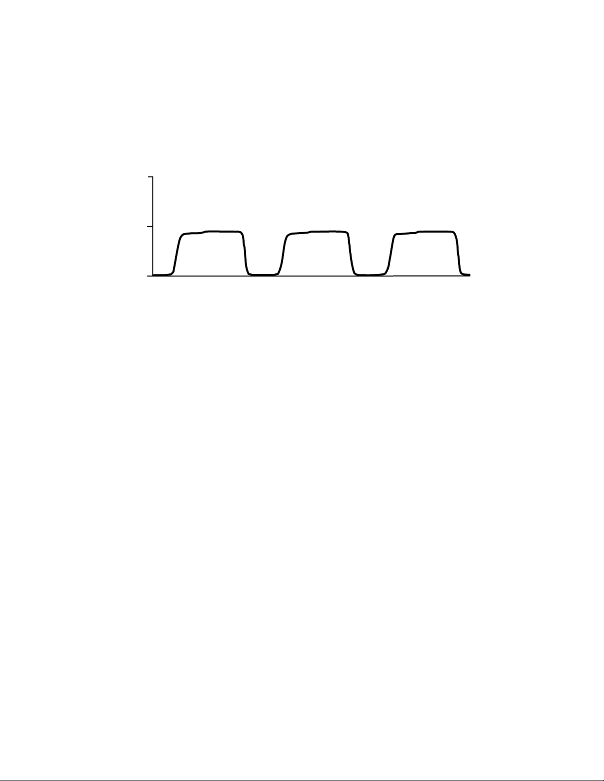
Capnography is the noninvasive measurement and graphic display of airway CO2 concentration
as a function of time. The resulting waveform is called a capnogram. The evaluation of the
capnogram is useful in the assessment of the adequacy of carbon dioxide exchange in the lungs,
integrity of the patient’s airway, cardiopulmonary function and ventilator function.
76
CO
2
40
(mmHg)
0
Capnogram Components
CD
AB
Time
E
Monitoring of CO2 concentration at the end of expiration (point D) is referred to as End-Tidal CO2
(ETCO2) monitoring.
Mainstream vs. Sidestream
The patient’s expired gas may be sampled either directly off the patient airway external to the
LC101 Module or aspirated from the patient through a cannula into the Module. The method used
is dependent on the patient’s airway status.
Mainstream capnography is typically used on intubated or tracheostomy patients and requires
the use of an external mainstream sensor. Intubation is the process of inserting a tube into the
patient’s trachea to deliver gases to the lungs.
Sidestream capnography is used on patients who are intubated or non-intubated. The patient’s
expired gas is aspirated from the airway and transported to the LC101 Module through a sample
line. The sidestream sample chamber and sensor are embedded within the LC101 Module.
Signal acquisition and measurement calculation are performed by the LC101 Module.
Measuring Principle
CO2 measurement is based on the Infra-Red (IR) absorption characteristics of CO2 molecules.
The CO
present in the sample gas. CO2 gas has a unique absorption band which is related to a CO2
molecule’s composition and mass. CO2 gas concentration is measured by detecting absorption in
this band. Due to the nature of the measurement technique employed, user calibration is
necessary with this system.
sensor uses non-dispersive IR spectroscopy to measure the number of CO2 molecules
2
Page 8 Confidential Welch Allyn OEM Technologies
Page 9
LC101 CO2 Module OEM Implementation Manual
Section 1 - Functional Description
The basic components of the CO2 sensor (C-Cap bench) include
• IR source
• Dual element IR detector
• optical filter
• non-volatile memory
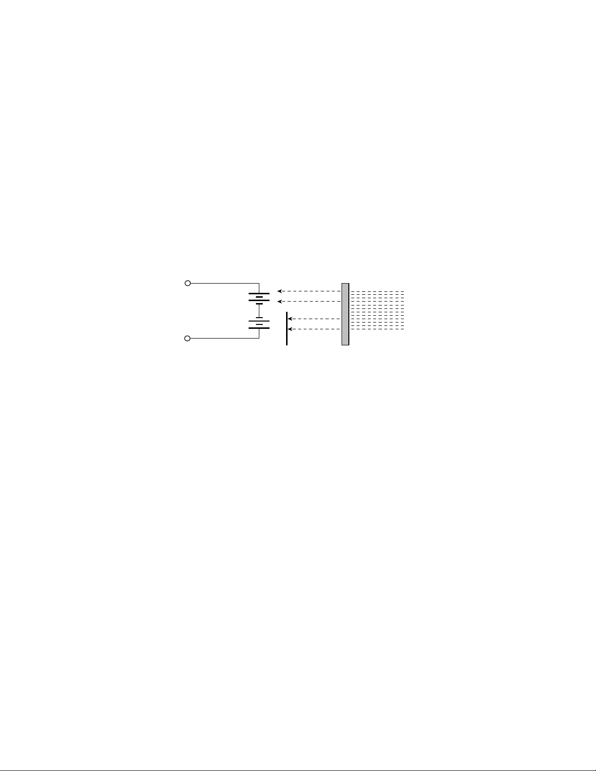
The IR source emits energy that is directed toward a dual element thermopile IR detector. The
dual element design uses two opposing thermopiles connected in series. As the ambient
temperature changes, the two elements change in similar fashion resulting in an output near
zero. Only one element is exposed to energy from the IR source, resulting in a voltage change
due to only that energy. The detector generates a voltage based on the amount of energy it
receives. In the IR path between the IR source and the detector is an
optical filter which allows
only a specific IR wavelength to pass and the gas sample within the sensor chamber.
Dual Element Thermopile
+
detector
output
element 1
element 2
+
narrowband
IR pass filter
energy
from IR
source
foil cover
CO2 Measurement Method
A temperature sensor is attached to the detector housing for temperature compensation beyond
the thermopile’s designed compensation, including temperature changes in the system
sensitivity. The detector generates a voltage in the mV range and an Op-amp on the circuit board
amplifies the signal.
The non-volatile memory is an EEPROM containing calibration and manufacturing data specific
to the CO
sensor.
2
Measurement Calculation
Measurements provided to the host system by the LC101 Module include ETCO2, Inspiratory
(InsCO2) and respiratory rate (RR). These three measurements are collectively referred to
CO
2
as breath data. A proprietary breath algorithm is used to calculate the breath data.
Breath Algorithm
Welch Allyn OEM Technologies’s breath algorithm incorporates an initial learning period which,
based on certain assumptions of CO
for threshold determinations. A sliding window is used to detect a stable maximum, or ETCO
waveform morphology, establishes CO2 reference points
2
2
value, and a baseline, or InsCO2 value. Thresholds are updated in real time with each breath. A
signal averaging technique is used to calculate the RR based on this set of measurements.
By incorporating these adaptive and signal averaging techniques, the breath algorithm effectively
reports accurate CO
measurements while maintaining a high level of noise immunity.
2
Welch Allyn OEM Technologies Confidential Page 9
Page 10

LC101 CO2 Module OEM Implementation Manual
Measurement Compensation
IR absorption in the CO2 wavelength band may be affected by a number of factors that alter the
measurement. The LC101 Module automatically compensates for some of these factors
CO
2
while others may be disabled by the host system.
These factors include
•water vapor
• pressure broadening
• gas mixing
•oxygen, nitrous oxide and desflurane or O2/N2O/desflurane
• Body Temperature, ambient Pressure and Saturated with water vapor or BTPS
Water Vapor
Water vapor compensation accounts for the effect that water vapor has on the IR absorption
characteristics of CO
adjusted mathematically to compensate for this effect.
molecules. During normal sidestream operation, CO2 measurements are
2
The host may choose to disable this compensation when performing dry gas measurements in
which the gas does not contain water vapor. Dry gas procedures may include steady state
measurements and calibration procedures. Steady state measurements are performed only
when background CO
of a steady state measurement is measuring the CO
, or CO2 present in the immediate environment, is measured. An example
2
content inside an incubator. Calibration
2
procedures use calibrated gas which is free of water vapor, or dry, as well.
The water vapor compensation is ON by default and may be enabled or disabled via a host
system command.
Pressure Broadening
Pressure broadening compensation accounts for the effect that barometric pressure has on CO2
molecule distribution and is used in both measurement and autorun modes.
The pressure broadening compensation is ON by default and cannot be disabled by the host
system.
Gas Mixing
A small amount of gas “mixing” occurs as the CO2 sample travels through the tubing to the
sample chamber. Gas mixing compensation accounts for the effect that low level gas mixing has
on the baseline, or InsCO2 measurement in both measurement and autorun modes. The gas
mixing, or baseline, compensation is ON by default and can be disabled by the host system.
Page 10 Confidential Welch Allyn OEM Technologies
Page 11

LC101 CO2 Module OEM Implementation Manual
O2/N2O/desflurane
O2/N2O/desflurane compensations account for the effects that these gases have on the IR
absorption characteristics of CO
description of this effect and a recommendation for enabling these compensations.
The O2/N2O/desflurane compensations are OFF by default and may be enabled or disabled via a
host system command.
BTPS
Often the clinician’s intent is to determine the CO2 levels within the patient’s lungs where gas
exchange is taking place. BTPS compensation corrects for the environmental differences
between the measurement site (i.e. the bench) and “deep lung” CO2.
The BTPS compensation is ON by default and may be enabled or disabled via a host system
command.
molecules. Refer to Appendix A Software Procedures for a
2
Section 1 - Functional Description
Hardware Components
LC101 Main Board
The LC101 Main Board provides the interface to the host system, manages power requirements,
calculates measurements, and regulates pump flow.
The functional components of the Main Board include
• 68HC11 microprocessor with external memory
• reset circuit
•primary power supplies
• analog to digital (A/D) converter
• digital to analog (D/A) converter
• source hybrid
• pressure transducers
68HC11 Microprocessor
The microprocessor controls feedback to the pump and to the temperature and pressure
transducer. The microprocessor also provides the communication interface to the host system
and interfaces to the external A/D and D/A converters and sensor EEPROM memory. An internal
multiplexed A/D converter is used for digital conversion and for monitoring some of the power
supplies for fault determinations.
All address decoding is performed by a microprocessor. The software code is stored in FLASH
memory and is supplemented by an external static RAM chip. The boot mode of the
microprocessor is used to install new software into the FLASH device.
Welch Allyn OEM Technologies Confidential Page 11
Page 12

LC101 CO2 Module OEM Implementation Manual
Reset Circuit
The first section of a 556 timer is connected to a serial receive data line such that the
microprocessor is forced into reset if the data line is held in a break condition for greater than 10
msec. A second timer section is used to determine if the break condition is maintained for more
than 500 msec.
Holding the receive data line in a break condition for a period of time greater than 10 msec and
less than 500 msec is referred to as a reset.
A hard reset occurs when the break condition is held longer than 500 msec. This condition
forces the microprocessor to enter the boot mode after the break is released.
Power ON, reset and low voltage lockouts are performed by a reset controller. Undervoltage
lockout is set to approximately 4.5 V. On power up, the microprocessor is held in reset for about
100 msec after the supply rises above 4.5 V.
Primary Power Supplies
All primary power supplies run off a single voltage power source and are converted on the Main
Board to various levels. The power source is derived from the (+5 V or +5.75 to +14.5 Vdc) Vin
power supplied by the host system.
A/D Converter
The 8 channel 12 bit serial A/D converter converts the following analog signals into a binary data
stream for the microprocessor: analog waveform from the optical bench, temperature of optical
bench, barometric pressure and pneumatic flow rate.
D/A Converter
The 12 bit serial interface D/A converter provides bench source current selection and bench
detector bias circuit control.
Source Hybrid
The optical bench requires that the IR source be current-regulated. The current-sensing circuitry
is located on a ceramic hybrid module, or source hybrid. A regulator is used that adjusts the
output voltage to maintain a constant current.
Pressure Transducers
The pressure circuitry monitors pressure via transducers in order to compensate for the effect of
pressure variation on the CO
measurement. The transducers include
2
• an absolute pressure transducer which initially provides an ambient pressure
measurement and then continuously monitors internal bench pressures during pump
operation.
•a differential pressure transducer which is used for pump flow regulation.
Due to the use of a single absolute pressure transducer, the ambient pressure
measurement is only updated at power on and watertrap replacement.
Page 12 Confidential Welch Allyn OEM Technologies
Page 13

LC101 CO2 Module OEM Implementation Manual
Section 1 - Functional Description
Sidestream Components
The functional components necessary for sidestream operation include
• pump
•watertrap and watertrap receiver assembly
• inlet and exhaust tubing
•CO2 sample line
• cannula
The flow control circuitry regulates flow by using a fixed orifice flow sensor that provides
feedback to a circuit that controls power to the pump. A differential pressure transducer
measures the pressure drop across a restrictor and this is used as feedback to adjust the pump
speed. The pump power supply steps down the raw voltage applied to the board to a level
appropriate for maintaining the desired pump flow rate.
The pump connector provides the electrical connection for the pump to the Main Board.
The watertrap receiver assembly connector provides the electrical connection for the
watertrap switch to the Main Board.
Pump
The electrically driven miniature oil-free diaphragm pump is mounted on the Main Board. The
pump draws the sample through the sample line to the sample chamber by creating a vacuum.
Fault states such as exhaust and watertrap occlusions are recognized by the flow control
circuitry. Refer to Section 5, Pneumatic Operation, for additional information on pump function.
Watertrap and Watertrap Receiver Assembly
NOTE The watertrap, watertrap receiver and receiver switch are not included with the LC101
Module and each may be ordered separately from Welch Allyn OEM Technologies or
supplied by the OEM.
The watertrap is a user-supplied cartridge that removes excess moisture in the sample line
before the sample is delivered to the sample chamber. The watertrap includes a built-in shutoff
pellet which is designed to fully occlude once the filter is saturated.
The functional components of the watertrap assembly include the watertrap receiver and
receiver switch.
The watertrap receiver is a receptacle for the watertrap and can be molded by the OEM into the
main housing of the host monitor (or purchased from Welch Allyn OEM Technologies as an
accessory). The external end of the watertrap is connected to the sample line.
The watertrap receiver switch provides a signal that is used for detection of a properly inserted
watertrap into the watertrap receiver before the pump begins operation. This eliminates the
possibility of the user bypassing the watertrap.
Welch Allyn OEM Technologies Confidential Page 13
Page 14
LC101 CO2 Module OEM Implementation Manual
Inlet and Exhaust Tubing
The internal inlet tubing provides the means to transport the gas sample from the watertrap
receiver to the sidestream bench. The inlet tubing includes the tubing, connectors and a
secondary shutoff pellet. Attachment of the inlet tubing to the watertrap receiver is via a Luer®
connector. A secondary shutoff pellet is attached in line with the inlet tubing to provide additional
backup.
The exhaust tubing provides the means to expel the exhaust gas. A 5 µm screen, or filter, is
positioned in line with the exhaust tubing to muffle, or reduce the pump noise.
CO2 Sample Line and Cannula
The CO2 sample line, or sample line, is used to transport the gas sample from the patient to the
watertrap assembly.
NOTE The sample line is not included with the LC101 Module and may be ordered separately
from Welch Allyn OEM Technologies or other suppliers.
For a non-intubated patient, the sample line connects to a cannula that is positioned on the
patient. A variety of cannulas are available to accommodate patient requirements. Nasal, oral/
nasal and divided cannulas which deliver oxygen and sample CO
simultaneously may be used.
2
NOTE Cannulas are not included with the LC101 Modules and may be ordered separately
from Welch Allyn OEM Technologies or other suppliers.
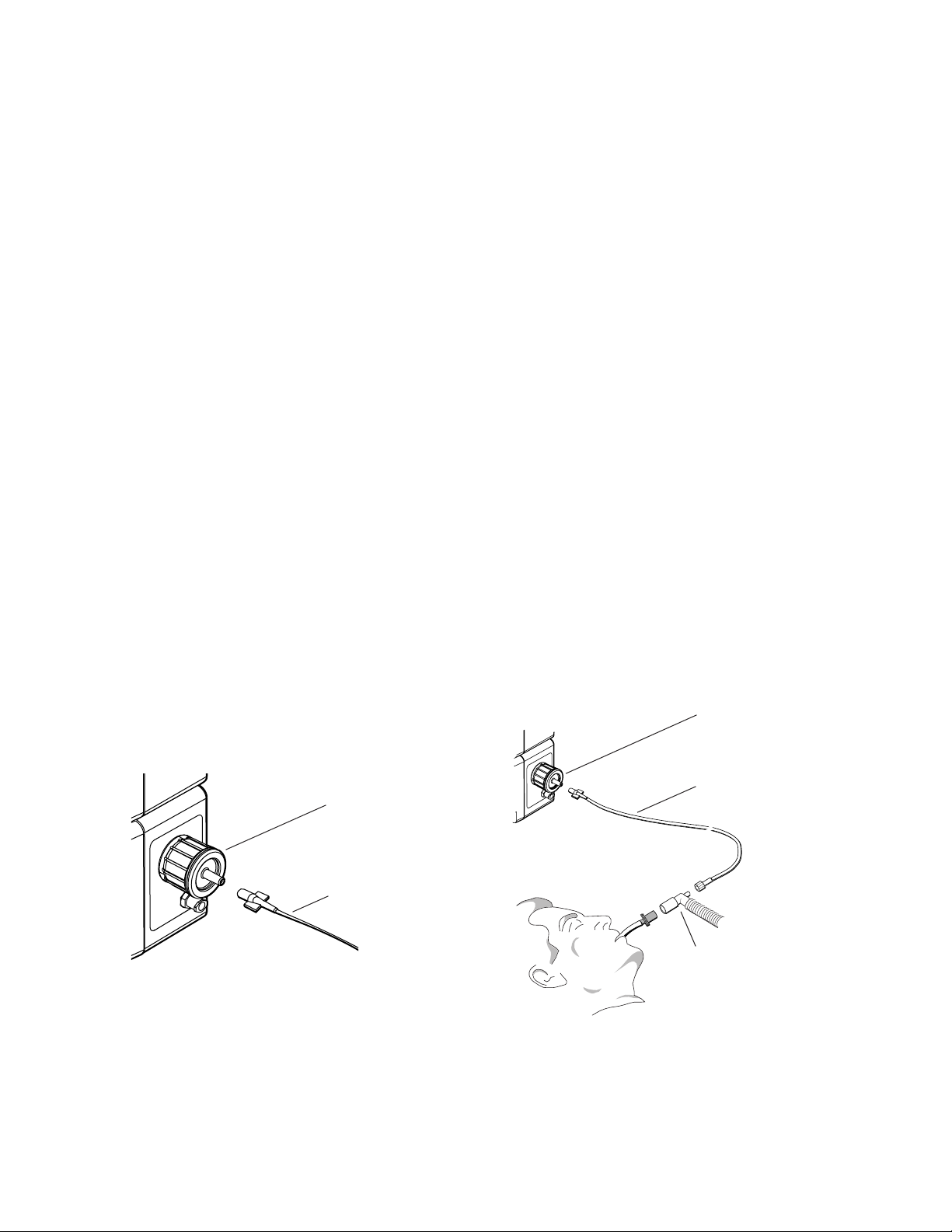
For an intubated patient, the sample line connects to the patient’s breathing circuit.
Sample connections for both intubated and non-intubated patients are shown below.
Watertrap
Sample line
Watertrap
Sample line
To cannula
Elbow connector
to breathing
apparatus
Typical Connection to Non-Intubated Patient
Typical Connection to Intubated Patient
Page 14 Confidential Welch Allyn OEM Technologies
Page 15

LC101 CO2 Module OEM Implementation Manual
Section 2
LC101 Module Interface
Power Requirements
Description Typical
Input voltage range 5 V regulated, or +5.75 to +14.50 Vdc
Ripple 100 mV peak-to-peak
Typical non-measurement mode power 570 mW at 8 Vdc
Typical operating power 1.3 W at 8 Vdc
Typical occluded power 1.5 W at 8 Vdc
LC101 Main Board
Description Specification
Dimensions 3.15 in. L x 3.90 in. W x 1.00 in. H
(80.3 mm × 99.3 mm × 25mm)
Orientation No limitations
Weight < 1 lb (454 gm)
Welch Allyn OEM Technologies Confidential Page 15
Page 16

LC101 CO2 Module OEM Implementation Manual
LC101 Module Interface Connector
The LC101 Module interface connector is a 4-pin connector (Molex P/N 22-11-2042). The host
may use a 4-pin polarized housing (Molex P/N 22-01-3047 with Molex 2759 series terminals) or
equivalent.
Pin Signal Signal Description
Vin
a
input power
1
2 gnd ground
3 TXD data from Main Board to host system
4 RXD data from host system to Main Board
a. The “square” plated through-hole designates pin 1 on the Main Board.
Watertrap Switch Connection
Watertrap switch connection is via a 2-pin Molex connector on the Main Board.
Pump
The pump is mounted on the Main Board. The pump wiring harness is connected to the Main
Board via a 2-pin connector (Molex P/N 22-01-3027).
The pump wiring meets typical insulation standards but does not meet patient isolation
requirements. If the pump must be moved to a different location, patient isolation requirements
must not be compromised. Refer to Section 6, Regulatory, for additional regulatory and safety
information.
Watertrap Receiver
The internal space available in the host monitor must be considered when incorporating the
watertrap receiver into the host system design. To accommodate various OEM dimensions, two
watertrap receivers are offered: long and short. The long watertrap receiver requires more
intrusion into the host monitor but the watertrap does not protrude as far externally from the host
chassis than with the short watertrap receiver.
Page 16 Confidential Welch Allyn OEM Technologies
Page 17

LC101 CO2 Module OEM Implementation Manual
Section 2 - LC101 Module Interface
Watertrap Receiver Switch
The watertrap receiver switch is wired in the “normally open” configuration.
The watertrap receiver switch connects directly to the Main Board via a wiring harness and
connector. The watertrap receiver switch assembly is equipped with a 2 pin connector (Molex
P/N 22-01-3027) which electrically connects directly to the Main Board at J102.
The watertrap receiver switch wiring meets typical insulation standards but does not meet patient
isolation requirements. When applicable, harness routing must not violate patient isolation
requirements. Refer to Section 6, Regulatory, for additional regulatory and safety information.
Exhaust Tubing
In the event of an exhaust tubing malfunction, gas buildup can occur within the host system.
WARNING To protect against potentially flammable gas buildup, the tubing must be
single-fault protected. Refer to Section 6, Regulatory, for additional regulatory
and safety information.
Welch Allyn OEM Technologies Confidential Page 17
Page 18

LC101 CO2 Module OEM Implementation Manual
Page 18 Confidential Welch Allyn OEM Technologies
Page 19

LC101 CO2 Module OEM Implementation Manual
Section 3
LC101 Calibration
The LC101 Module requires periodic user calibration to adjust offset voltages and calibration
constants used by the internal C-Cap bench. There are two types of calibration, each supported
in the LC101 software protocol:
• Zero Calibration
•Two-Point User Calibration
Zero Calibration
The Zero Calibration adjusts the offset voltage used by the C-Cap to generate the CO2 values
and the IR source current. The required frequency of Zero Calibration depends on the amount
and type of usage, and may be typically required every two weeks. The LC101 does not monitor
the elapsed time between calibrations, nor does it alert the host when calibration is needed. It is
up to the host system and the end-user to determine when calibration is required.
The procedure requires the use of clean, dry air (0% CO2) at room/ambient temperature. In
order to provide the 0% CO
used to absorb CO
eliminates CO
Allyn OEM Technologies.
The scrubber is designed to be attached directly to the Welch Allyn OEM Technologies watertrap
by the user before a Zero Calibration. The scrubber is removed after successful calibration. The
scrubber has a shelf life of approximately one year. Although the scrubber is considered reusable, its effective life depends on application and exposure to CO
concentration in the zero reference gas and will alert the host system, when polled for
CO
2
status, if a problem exists with the sample zero gas.
from room air. The scrubber contains a chemical which reacts with and
2
as it is drawn through the scrubber. The CO2 scrubber is available from Welch
2
, an external device, called a “CO2 scrubber” (or CO2 absorber), is
2
. The LC101 monitors the
2
Welch Allyn OEM Technologies Confidential Page 19
Page 20

LC101 CO2 Module OEM Implementation Manual
To get an accurate calibration, the LC101 needs to be operating for at least 5 minutes in
measurement or autorun mode with the scrubber installed. The LC101 internally monitors the
run time and will not allow a Zero Calibration if the run time requirement has not been met.
The LC101 monitors the calibration progress and provides a “Calibration OK” (or “not OK”)
message to the host system when polled for status. See the LC101 Software Protocol and the
Zero Calibration Commands and Responses for more detail. After a successful Zero Calibration,
the LC101 updates the zero residual offset constants located in the LC101 C-Cap EEPROM
Memory and the IR source current.
Zero Calibration Procedure
Equipment needed:
• watertrap
•CO2 scrubber (or 0% CO2 medical-grade gas source; see the Two-Point User
Calibration procedure for pressurized gas setup)
To Perform a Zero Calibration:
The user is required to apply a 0% CO2 gas, or “zero” gas, during the steps of a Zero Calibration.
To perform Zero Calibration, the user must follow the Original Equipment Manufacturer’s
procedure typically provided in the Operator’s Guide or User Service Manual.
1. Select a well ventilated room to perform the calibration.
2. Make sure the LC101 has been operating for at least 5 minutes prior to the Zero Calibration.
3. Attach the CO2 scrubber to the watertrap inlet according to the CO2 scrubber “Directions for
Use” (or attach a 0% medical-grade gas source). Now let the LC101 operate for one
minute.
4. After approximately one minute, observe the CO2 reading. The CO2 reading should be
between 0.0% - 0.3% with well-ventilated room air.
5. Proceed with the zero gas phase of the calibration as defined by the host system.
6. Disconnect the CO2 scrubber (or gas source) from the watertrap after the zero gas calibration.
Page 20 Confidential Welch Allyn OEM Technologies
Page 21

LC101 CO2 Module OEM Implementation Manual
Section 3 - LC101 Calibration
Two-Point User Calibration
NOTE Before performing a Two-Point User Calibration, a separate Zero Calibration must be
performed first. It is also recommended that both calibrations be performed at 75ºF in
order to maintain accuracy over the Module’s operating temperature range.
The Tw o-Point User Calibration, or User Calibration, updates two of the gas calculation constants
used to generate the CO
amount and type of usage. Typically it may be required every six months. The LC101 does not
monitor time between calibrations, nor does it alert the host when calibration is needed. It is up
to the host system and the end-user to determine when calibration is required.
To get an accurate User Calibration, the LC101 needs to be operating for at least 5 minutes in
measurement or autorun mode. The LC101 internally monitors the run time and will not allow a
User Calibration if the run time requirement has not been met.
To perform the User Calibration, the host is required to supply a calibration date, a span gas
concentration, and indicate the gas concentration being applied to the LC101 Module (0% or the
span gas).
values. The required frequency of User Calibration depends on the
2
The OEM typically provides a User Calibration Kit to the end user containing a CO2 reference
gas with regulator, scrubber, directions for use, adapter, and tubing.
The LC101 monitors the User Calibration progress and provides a “Calibration OK” (or “not OK”)
message to the host system after successful calibration when polled for status. See the LC101
Software Protocol and the User Calibration Commands and Responses for more detail. After a
successful User Calibration, the LC101 updates the User Calibration History Queues located in
the LC101 C-Cap EEPROM Memory.
Zero and User Calibration dates should be user accessible via a host service screen or other
means.
Welch Allyn OEM Technologies Confidential Page 21
Page 22
LC101 CO2 Module OEM Implementation Manual
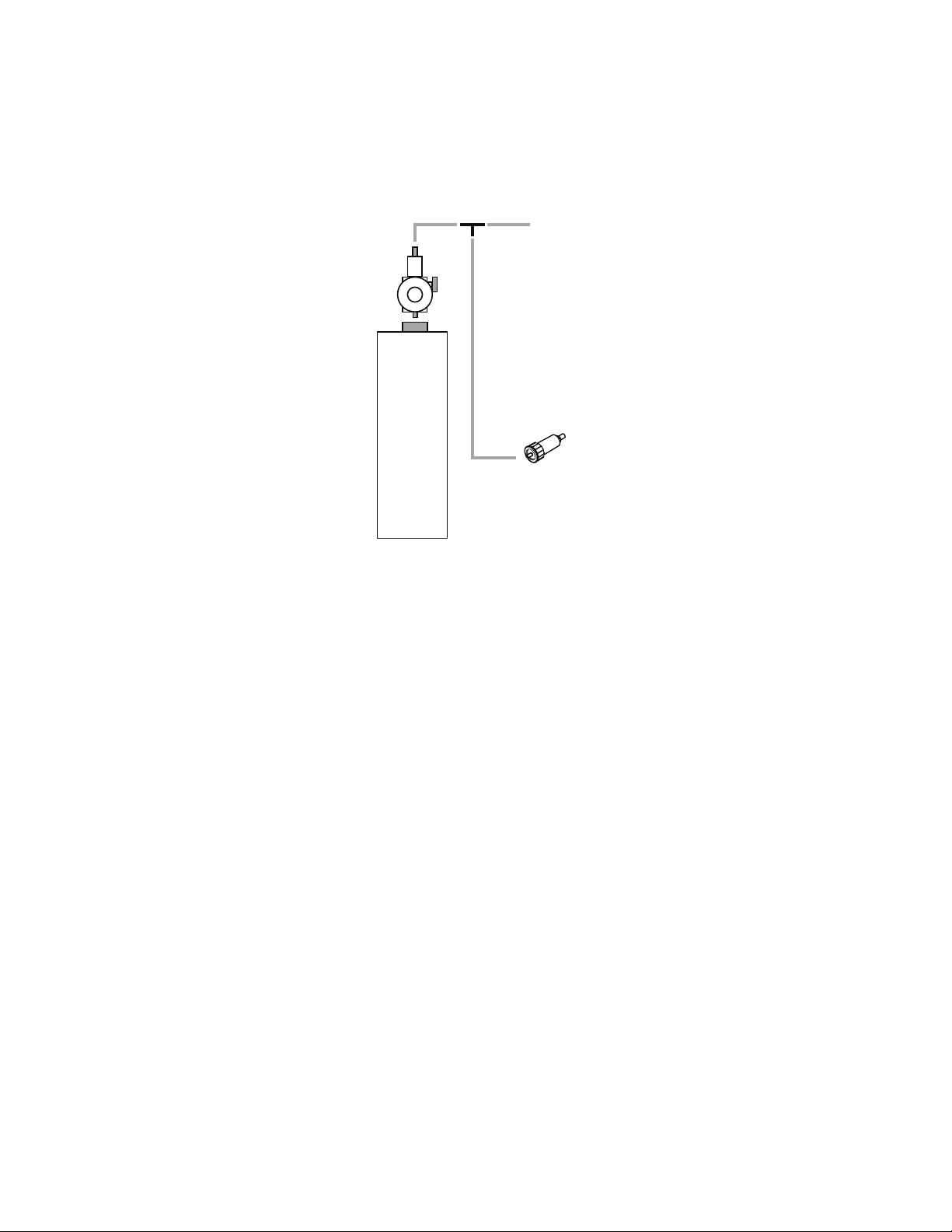
Two-Point User Calibration Procedure
Illustration of gas canister,
regulator and pneumatic circuit
Equipment needed:
• calibration gas canister (8 – 12% CO2, ±0.02%, balance air or nitrogen)
Regulator
Te e
On/Off
10%
CO2
Bal. N2
Free Flow Away
From Monitor Input
Water Trap
To Monitor
Two-Point User Calibration Equipment Setup
• gas valve and non-silicon tubing
• sample elbow or tee
•flow meter
• sample line
•watertrap
•CO2 scrubber (or 0% CO2 medical-grade gas source)
CAUTION Make sure that the tubing used to connect the gas supply to the LC101 does
NOT contain silicon. Silicon tubing absorbs CO
and affects the stability of
2
the gas concentration, thereby reducing the accuracy of the procedure.
Page 22 Confidential Welch Allyn OEM Technologies
Page 23

LC101 CO2 Module OEM Implementation Manual
Section 3 - LC101 Calibration
To Perform a Two-Point User Calibration:
The user is required to apply a 0% CO2, or “zero” gas, and also apply a gas of known CO2
concentration (referred to as “span” gas) during the various steps of a Two-Point User
Calibration. The user is required to manually enter the value of the Span Gas applied into the
Monitor.
To perform the Two-Point User Calibration, the user must follow the Original Equipment
Manufacturer’s procedure typically provided in the Operator’s Guide or User Service Manual.
(Refer to illustration on
page 22.)
1. Select a well-ventilated room to perform the calibration.
2. Let the LC101 run for at least 5 minutes prior to calibration.
3. For the “Sample Zero Reference Gas” step, attach the CO2 scrubber to the watertrap inlet
according to the CO
scrubber “Directions for Use” (or use a 0% medical-grade gas source).
2
4. Proceed with the zero gas phase of the calibration as defined by the host system. Disconnect CO2 scrubber (or 0% gas source) from the watertrap after the zero gas phase and prior
to the next calibration step.
5. For the “Sample Span Reference Gas” phase of the calibration, provide a medical-grade
gas source with a known CO
concentration between 8% and 12%, regulated to a pressure
2
between 5 and 7 psi.
NOTE Do not apply any pressure directly to the Module inlet or outlet.
6. Introduce a steady stream of CO2 gas. Set and monitor the flow rate to approximately
liter/minute (±10%). To verify flow, place the bleed line of the calibration sample line in a
1
glass of water. If bubbles emerge, gas supply is sufficient. If no bubbles emerge, there is an
insufficient supply of gas.
7. Connect a sample line from the sample elbow, or Tee, as shown above, to the Monitor’s
watertrap inlet. Make sure the bleed line is directed away from the monitor. Allow the refer
ence gas to flow for at least one minute.
8. Sample the Span Reference Gas.
9. After the Two-Point User Calibration steps have been followed, disconnect the LC101 from
the gas supply and test setup.
10. A verification may be performed using the same gas delivery set up. Verify the observed
CO
gas reading is within 3 mmHg or 10%, whichever is greater, of the CO2 value of the test
2
gas supplied. (If not, refer the user to the appropriate troubleshooting information.)
-
Welch Allyn OEM Technologies Confidential Page 23
Page 24

Troubleshooting
• Make sure that the room is well ventilated. CO2 readings may be elevated in a closed
room.
• Confirm that the calibration gas is of known concentration. If the CO2 readings are
consistently elevated or depressed, the calibration gas may be suspect. Try another
gas source.
• Make sure that the CO2 module was properly set up and operating for the required
minimum period before testing.
• Check for air leaks in the pneumatic tubing and connections. Repair or replace as
needed.
• Confirm that the sample gas flow rate is greater than the CO2 module’s pump flow
rate.
• Confirm that silicon tubing is not used in the procedure (silicon absorbs CO2 which
affects the gas concentration stability and accuracy of the procedure).
LC101 CO2 Module OEM Implementation Manual
Page 24 Confidential Welch Allyn OEM Technologies
Page 25

LC101 CO2 Module OEM Implementation Manual
Section 4
Host/Module Communications
The LC101 Module is a command driven slave device capable of communicating with a host
system over an asynchronous serial communication line. After the host system commands the
LC101 Module to begin transmission of CO
sends periodic packets without additional intervention by the host system. The host system must
initiate all other communication with the LC101 Module.
waveform and breath data packets, the Module
2
The LC101 Module and the host system are referred to as the “Module” and “host” in the
remainder of this section.
Communication Interface
• 9600 baud rate
• full duplex
• asynchronous using standard non return to zero (NRZ) format.
{1 start bit 7 or 8 data bits even parity 1 stop bit}
• Receive data input (RxD) is the buffered input of a 74HC14. A pull up is provided on
the Module so it can be driven by an open collector source.
•Transmit data output (TxD) is the collector of a 2N4401 transistor driven with a 10 K
base resistor from the output of a 74HC14. A weak pull up is provided to source a
CMOS load.
• Module power and communications are provided at J101.
Welch Allyn OEM Technologies Confidential Page 25
Page 26

LC101 CO2 Module OEM Implementation Manual
System EEPROM
The system EEPROM contains manufacturing and operational data that is necessary for the
LC101 Module to function. A limited number of these system parameters may be specified by the
OEM. These include
• data format
• start up mode
• initial pump flow rate
The data format options are 7 and 8 data bits (default is 7E1).
The start up mode options are auto run, measurement, standby and fault (default is standby).
The initial pump flow rate option allows the host to specify the default pump flow rate in
milliliters per minute (default is 150 ml/min).
Packet Structure
Transmission of host commands and Module responses is via packets. The following byte
structure represents a packet.
Packet format:
< start of text (STX) 02h
X identifier 1*(ASCII)
n
xx
yy CCITT/CRC code 2*(ASCII)
> end of text (ETX) 03h
ASCII characters have values in the range of 00h to 7Fh. The identifier is case sensitive.
Characters between 00h and 20h are reserved as control characters.
Tr ansmission of all packets starts with a “<” STX control character and ends with a CCITT/CRC
code and “>” ETX control character. Between STX and ETX is an identifier and n bytes of ASCII
data. The length of the packet is defined by the identifier character. Packet length cannot exceed
25 bytes with a maximum of 20 bytes of data allowed. Packets without the STX control character
are ignored. The CCITT/CRC code is calculated on values between STX and CCITT/CRC code.
data n(hex char)
Example:
02h X xxn yy 03h
Page 26 Confidential Welch Allyn OEM Technologies
Page 27

LC101 CO2 Module OEM Implementation Manual
Section 4 - Host/Module Communications
Host Commands
The host communicates to the Module via commands. These include:
• mode commands to request a change in the operating mode.
• simple commands to request data or a status change. Data is not sent with these
commands.
• configuration commands to specify custom system settings. Data is sent with these
commands.
• calibration commands to request a Zero or User Calibration sequence. Data is sent
with these commands.
Mode Commands
Mode commands allow the host to put the Module into one of the three operating modes.
Host Command Description
<M24> Enter auto run mode
To start automatic sampling and data packet transmission at default
intervals of realtime CO2 waveform and breath data. A watertrap
removal causes the Module to wait for a watertrap insertion. This is
the preferred operating mode since temporary watertrap
removal and replacement is typical in normal operation.
<M23> Enter measurement mode
Same as auto run mode except for sidestream watertrap removals.
Instead of waiting for watertrap insertion, the sensor’s activity is
halted and the Module reverts to the standby mode and requires a
new <M23> host command to restart measurement.
<M21> Enter standby mode
Used when a low power standby state for the Module is desirable.
This prolongs the life expectancy of the IR source, since this component is disabled in this mode.
No more than two mode commands should be issued in any five-second period.
The Module automatically reverts to fault mode if a Module or sensor fault occurs. A fault
message is sent via the status response by the Module to the host when polled for status.
Welch Allyn OEM Technologies Confidential Page 27
Page 28

LC101 CO2 Module OEM Implementation Manual
Simple Commands
Simple commands instruct the Module to send Module data or EEPROM data and to reset the
Module software or reset sensor error.
Host Command Description
<C00> Request and confirm operating mode and Module status
<C20> Request software version
<C21> Request hardware version
<C22> Request ambient barometric pressure
<C23> Request sensor temperature
<C26> Request single CO2 measurement
<C27> Request single breath data packet
<C2E> Request current set flow rate
<C31> Request sensor EEPROM revision #
<C32> Request sensor manufacturer code
<C33> Request sensor serial #
<C3A> Request last calibration date
Page 28 Confidential Welch Allyn OEM Technologies
Page 29

LC101 CO2 Module OEM Implementation Manual
Section 4 - Host/Module Communications
Configuration Commands
Configuration commands instruct the Module to temporarily modify specific default settings for
measurement criteria. A new pump flow rate may also be specified. The host does not have to
command the Module into the unprotected mode prior to issuing a new flow rate command.
A description of these commands is included in the following table.
Host Command Description
<Nxx> Change CO2 waveform update rate
Allows the host to specify how often the Module sends a CO2 waveform data packet. The Module generates a CO2 measurement every
31msec. The maximum update rate is 31 msec. The host may program the rate to xx increments, where xx is the number of 31msec
increments per packet.
<Nxx> where xx (ASCII) defines the CO2 waveform update rate
based on the number of 31msec increments.
xx range 00h to FFh
xx default 01h, 31 msec interval
Examples:
<N01> send a CO2 waveform data packet every 31 msec (1 × 31
msec)
<N05> send a CO2 waveform data packet every 155 msec (5 ×
31 msec)
<NFF> send a CO2 waveform data packet every 7.9 seconds
(255 × 31 msec)
<N00> stop sending waveform data
<Axx> Change breath data clear rate
Allows the host to specify how long the Module waits for a new
breath data packet before clearing the breath data (ETCO2 = 00h /
RR = 00h / InsCO2 = 00h).
<Axx> where xx (ASCII) defines the “no breath” timeout in sec-
onds
xx range 10 to 60 s (0Ah to 3Ch)
xx default 0Fh, clear breath data after 15 s of “no breath”
Example:
<A0A> clear the breath data after 10 seconds of “no breath”
Welch Allyn OEM Technologies Confidential Page 29
Page 30

LC101 CO2 Module OEM Implementation Manual
<Oxx> Change breath data update rate
Allows the host to specify how often the Module sends a breath
data packet.
<Oxx> where xx (ASCII) is converted to a 8 bit binary number (yyzz
zzzz) with yy defining how often the breath data is
updated.
If yy = 00 binary, Breath data packet update rate is defined by
zzzzzz, where zzzzzz is in tenths of seconds. The 6
lower bits = (seconds × 10).
to even values.
If yy = 01 binary, Breath data packet update rate is every breath
where zzzzzz = doesn’t matter.
Exception: If the “no breath” condition occurs, data is sent
at 1 second increments.
If yy = 10 binary, Breath data update rate is when the data changes,
where zzzzzz = doesn’t matter.
Exception: If after 15 seconds the breath data has not
changed, data is sent after the next breath. This does not
guarantee a 15 second update; however, if the “no breath”
condition has occurred, the “no breath” timeout takes precedence.
Exception: If the “no breath” condition occurs, data is sent
at 1 second increments.
If yy = 11 binary, Not defined.
Examples
<O05> send a breath data packet at .6 s interval (Odd values
<O40> send a breath data packet every breath
<O80> send a breath data packet every time the data changes
Special case:
<O00> no breath data sent (Note: Continuous CO2 mode would
:
rounded up)
use this command.)
Odd values are rounded up
Page 30 Confidential Welch Allyn OEM Technologies
Page 31

LC101 CO2 Module OEM Implementation Manual
<Qxxy> Function enable
Allows the host to enable or disable functions listed below.
<Qxxy> where xx (ASCII) is the compensation and y (ASCII) is
ON/OFF status.
xx =
00h O2 compensation
01h N2O compensation
02h desflurane compensation
08h water vapor compensation
09h BTPS compensation
0Ah baseline compensation
7Fh protect mode
y =
00 binary ON
01 binary OFF
3Fh current ON/OFF status
Example
<Q011> compensate the CO2 waveform data for N2O
<Q7F0> turn off protect mode (to allow certain commands)
Section 4 - Host/Module Communications
<F20yy> Change pump flow rate
Allows the host to specify the pump flow rate in milliliters per
minute.
<F20yy> where yy (8 bit) is the current pump flow rate.
yy range 90 – 200 ml/min (5Ah – C8h)
yy default 175 ml/min (AFh)
Example
<F205A> set the pump flow rate to 90 ml/minute
Note: Using this command to set a desired flow rate, the pump flow
rate will revert back to default settings upon power up. The flow rate
can be fixed in the EEPROM to a specific default setting. See
EEPROM Map for location details.
<C80> Request software reset
Allows the host to reset the Module. This command is only
accepted if the Module is in the unprotected mode. See Function
enable <Qxxy>.
Welch Allyn OEM Technologies Confidential Page 31
Page 32

LC101 CO2 Module OEM Implementation Manual
Calibration Commands
Calibration commands instruct the Module to update the gas calculation or the zero offset
constants used to generate the CO
are stored in EEPROM memory. Data is required with these commands. There are two types of
calibration: Two-Point User Calibration and Zero Calibration.
Two-Point User Calibration
TheTw o-Point User Calibration updates two of the gas calculation constants used to generate the
CO
values. To perform a User Calibration, the host is required to supply a calibration date and a
2
span gas concentration.
When performing a User Calibration, the LC101 Module must first be in either Unprotected
'Measurement' or 'Autorun' mode. During the calibration, CO
be sent to the host.
To get an accurate calibration, the LC101 Module needs to be operating for at least 5 minutes in
measurement or autorun modes. The LC101 will not allow a calibration if this requirement has
not been met. In addition, the calibration should be performed at room/ambient temperature.
values. At the end of a successful calibration, new constants
2
waveform and Breath data will still
2
Host Command Description
<Lmmddyyyy> Update calibration date.
Allows the host to enter a new calibration date from user input into
EEPROM memory.
<Lmmddyyyy> mm = month, dd= day, yyyy= year
Note: The mmddyyyy fields are decimal values.
Example
<L01012000> calibration date = January 1, 2000
<Gxx> Update span gas concentration.
Allows the host to enter a gas concentration value from user input.
<Gxx> xx = percent CO2 x 16.
Example
<GA8> span gas concentration = 10.5%
<C10> Sample zero reference gas.
<C11> Sample span reference gas.
<C13> Abort calibration
:
:
After a successful calibration, the Module updates the User Calibration History Queues located
in the
C-Cap EEPROM Memory Map
.
Page 32 Confidential Welch Allyn OEM Technologies
Page 33

LC101 CO2 Module OEM Implementation Manual
Zero Calibration
The Zero Calibration adjusts the IR source current to compensate for detector output changes.
The host is required to inform the LC101 Module when to start sampling 0% CO
When performing a Zero Calibration, the LC101 Module must first be in either Unprotected
'Measurement' or 'Autorun' mode. During the calibration, CO
be sent to the host.
To get an accurate calibration, the LC101 Module needs to be operating for at least 5 minutes in
measurement or autorun modes. The LC101 will not allow a calibration if this requirement has
not been met. In addition, the calibration should be performed at room/ambient temperature.
Host Command Description
<C12> Perform Zero Calibration
<C13> Abort Calibration
Section 4 - Host/Module Communications
gas.
2
waveform and Breath data will still
2
After a successful Zero Calibration, the Module updates the zero residual offset constants
located in the
C-Cap EEPROM Memory Map
.
Module Responses
The host must initiate all communication with the Module with the exception of periodic CO2
waveform and breath data packets. The type of response sent is determined by the type of host
command. Responses include:
• status responses
• mode command responses
• simple command responses
• configuration command responses
• calibration command responses
Welch Allyn OEM Technologies Confidential Page 33
Page 34

LC101 CO2 Module OEM Implementation Manual
Status Responses
Status responses are data packets that communicate Module, sensor and system status. The
status response also serves as an acknowledgement for mode commands.
Status response packet format:
< STX 02h
X identifier 1*(ASCII)
xx mode 2*(ASCII)
yy message 2*(ASCII)
zz CCITT/CRC code 2*(ASCII)
> ETX 03h
NOTE: To simplify the Module status response examples that follow, the CRC data (zz) is
assumed to be included with the ETX character (>).
Status Response Mode Byte
The format of the Mode byte is as follows:
<Sxxyy> where S = Identifier
xx = Mode
yy = Status message
(1 byte = 1 ASCII character)
(2 Hex digits = 2 ASCII characters)
(2 Hex digits = 2 ASCII characters)
Status Response Mode Byte - Format Summary
bit 7* bit 6* bit 5* bit 4** bit 3** bit 2 bit 1 bit 0
Status
Response xx
<S61yy> Standby 0 1 1 0 0 0 0 1
<S63yy> Measurement 0 1 1 0 0 0 1 1
<S64yy> Autorun 0 1 1 0 0 1 0 0
<S65yy> Fault 0 1 1 0 0 1 0 1
Mode
8 4 2 1 8 4 2 1
*Bits 5 and 6 will always be set to 1; Bit 7 will always be set to 0.
**Bits 3 and 4 are always zero as there are only 4 modes (values 0, 2, and 6 to 31 are undefined).
Page 34 Confidential Welch Allyn OEM Technologies
Page 35

LC101 CO2 Module OEM Implementation Manual
Section 4 - Host/Module Communications
Status Response Message Byte
<Sxxyy> where yy =
Status message (2 Hex digits = 2 ASCII characters)
Status Response message byte (yy) contains:
• generic status messages (00h – 06h)
•fault status messages (10h – 85h)
Refer to the Status Message Table at the end of this section for message descriptions. More
detailed information about fault messages is also available in Appendix C, Error Messages &
Recovery.
Mode Command Responses
Host Command Module Response Module Response Format
<M21>
Enter standby mode
<M23>
Enter measurement mode
<M24>
Enter auto run mode
<S6106> xx = mode
yy = message
Example:
<S6106>
61= Standby mode
06= Acknowledge mode command
<S6306> xx = mode
yy = message
Example:
<S6306>
63= Measurement mode
06= Acknowledge mode command
<S6406> xx = mode
yy = message
Example:
<S6406>
64= Autorun mode
06= Acknowledge mode command
Welch Allyn OEM Technologies Confidential Page 35
Page 36

LC101 CO2 Module OEM Implementation Manual
Simple Command Responses
Host Command Module Response Module Response Format
<C00>
Request Module status
<C20>
Request software version
<C21>
Request hardware version
<C22>
Request stored ambient baro-
metric pressure reading from
absolute pressure transducer
<Sxxyy> xx = mode
yy = message
Example:
<S6400>
64= Autorun mode
00= OK status
<Vxxxmmddyyyy> xxx = version #
mm = version month
dd = version day
yyyy = version year
Example:
<V13010231998>
version = 1.30
date = 10-23-1998
<Hxx> xx = hardware version
Example:
<H25>
hardware version = 2.5
<Lxxxx> xxxx = amb baro pressure mmHg
Examples:
<L02E9>
amb baro pressure = 745 mmHg
<L02F8>
amb baro pressure = 760 mmHg
<C23>
Request sensor temperature
<Txx>
xx = (temperature x 4) oC
Example:
<T2A>
temperature = (42/4) = 10.5oC
<C26>
Request single CO2 packet
<wxxyy> xxyy = ppCO2 x 256
CO2 = 16 bit binary integer
Example:
<w1C5B>
waveform = 28.35
Page 36 Confidential Welch Allyn OEM Technologies
Page 37

LC101 CO2 Module OEM Implementation Manual
Section 4 - Host/Module Communications
<C27>
Request single breath packet
<C2E>
Request current pump flow rate
<C31>
Request sensor EEPROM revi-
sion #
<zxxyyww> xx = ETCO2 mmHg
yy = RR bpm
ww = InsCO2 mmHg
Example:
<z201500>
ETCO2= 32
RR= 21
InsCO2= 0
<Bxxxx> xxxx = pump flow rate ml/min
Example:
<B0096>
flow rate = 150 ml/min
<Rxx> xx = revision #
Example:
<R02>
revision # = 2
<C32>
Request sensor customer code
<C33>
Request sensor serial #
<C3A>
Request last calibration date
<Ixx> xx = customer code
Example:
<I00>
customer code = 00
<Nxxxx> xxxx = serial #
Example:
<N34C2>
serial # = 13506
<Dmmddyyyy> mm = month
dd = day
yyyy = year
Example:
<D06041998>
last cal date= 6/4/1998
Welch Allyn OEM Technologies Confidential Page 37
Page 38

LC101 CO2 Module OEM Implementation Manual
Configuration Command Responses
Configuration responses are data packets sent by the Module to the host at programmed
intervals. A single host measurement or auto run mode command initiates unsolicited
transmission of CO
packets is either defined by the host via a configuration command or the host may use the default
setting.
Module Response Module Response Format
waveform and breath data packets. The programmed interval between
2
<Wxxyy>
Unsolicited CO2 waveform packet at programmed interval
<Zxxyyzz>
Unsolicited breath data packet at programmed interval
see below
see below
<Wxxyy>, CO2 Waveform Data
Includes 4 bytes of CO2 waveform data that are sent at the programmed interval during
measurement and auto run modes.
<Wxxyy> where xxyy:
xxyy CO2 waveform data mmHg × 256 4*(ASCII)
range: 0 – 99.996 mmHg (0000h – 63FFh)
Example:
CO2 = 37.50 mmHg
{STX} “W” xx yy CCITT/CRC {ETX} waveform byte string
0x25 0x80 0x79 {STX}W258079{ETX}
02h 57h 32h35h 38h30h 37h39h 03h
Page 38 Confidential Welch Allyn OEM Technologies
Page 39

LC101 CO2 Module OEM Implementation Manual
Section 4 - Host/Module Communications
<Zxxyyzz>, Breath Data
Includes 6 bytes of breath data that are sent at the programmed interval during measurement
and auto run modes.
<Zxxyyzz> where xxyyzz:
xx ETCO2 mmHg 2*(ASCII)
yy RR bpm 2*(ASCII)
zz InsCO2 mmHg 2*(ASCII)
Range:
ETCO
2
0 – 99 mmHg (00h – 63h)
RR 0 – 250 bpm (00h – FAh)
InsCO
Example:
2
0 – 99 mmHg (00h – 63h)
ETCO2 = 39 mmHg / RR = 12 bpm / InsCO2 = 0 mmHg
{STX} “Z” xx yy zz CCITT/CRC {ETX} breath byte string
0x27 0x0C 0x00 0x1A {STX}Z270C001A{ETX}
02h 5Ah 32h37h 30h43h 30h30h 31h41h 03h
Additional Configuration Command Responses
Host Command Module Response Description
<Axx>
Change breath data clear rate
<Nxx>
Change waveform update rate
<axx> response = echo data field
<nxx> response = echo data field
<Oxx>
Change breath data update rate
<Qxxy>
Function enable
<F20yy>
Change pump flow rate
<C80>
Request software reset
<oxx> response = echo data field
<qxxy> response = echo new/current status
<F20yy> response = echo data field
no response
Welch Allyn OEM Technologies Confidential Page 39
Page 40

LC101 CO2 Module OEM Implementation Manual
Calibration Command Responses
Host Command Module Response Module Response Format
<Lmmddyyyy>
Update calibration date
<Gxx>
Update span gas concen-
tration
<C10>
Sample zero reference gas
<Sxxyy> xx = mode
yy = message
Example:
<S6424>
64= Autorun mode
24= Cal. ready for next step
Example:
<S6421>
64= Autorun mode
21= Cal. already in progress
<Sxxyy> xx = mode
yy = message
Example:
<S6424>
64= Autorun mode
24= Cal. ready for next step
Example:
<S6422>
64= Autorun mode
22= Cal. not in progress
<Sxxyy> xx = mode
yy = message
Example:
<S6425>
64= Autorun mode
25= Cal. in progress
<C11>
Sample span gas
<Sxxyy> xx = mode
yy = message
Example:
<S6425>
64= Autorun mode
25= Cal. in progress
<C13>
Abort calibration
<Sxxyy> xx = mode
yy = message
Example:
<S6400>
64= Autorun mode
00= OK (operation aborted)
Refer to the Status Message Code Table and the Host Command/Module Response Overview
Ta ble at the end of this section for message descriptions.
Page 40 Confidential Welch Allyn OEM Technologies
Page 41

LC101 CO2 Module OEM Implementation Manual
Software Protocol
Packets
• Module must respond within 1 second after receiving a host command (50 msec
typical response time).
• There is no minimum time interval between packets.
• Host must request Module status periodically to confirm the fault/OK status of the
Module and sensor.
• Host must either receive a Module response or have exceeded the Module response
timeout of 1 second before issuing a new command.
• There are no restrictions when switching from mode to mode.
•A packet that interrupts another packet causes the interrupted packet to be ignored.
• An incomplete or incorrectly formatted packet is ignored.
• Status messages have identical meanings in all operating modes.
Section 4 - Host/Module Communications
Faults
WARNING The host should not assume that the Module is faultless if CO2 waveform and
breath data is being sent. Data response packets may be communicated when
the Module is in a non-fatal fault, or soft fault state.
• If a fault occurs and the host issues a new mode command that is different from the
current mode, the Module responds with either a hard fault status and ignores the
mode command, or retries by attempting to clear the fault.
• If the Module is in a soft fault state, the host should issue a new measurement mode
command to attempt to clear the fault.
•A fault condition may leave the Module in the fault mode indicated by a <Sz5yy> status
response. For <Sz5yy>, yy is the status message and z is the other status.
Module Resets
External Resets (Initiated by the Host System)
• Software Reset - The host may command a software reset using the <C80>
command while the Module is unprotected. After the reset, the Module returns to its
EEPROM default settings.
• Reset - If the host holds the receive data line in a break condition for greater than 10
msec, but less than 500 msec, the microprocessor is forced into reset. After the reset,
the Module returns to its EEPROM default settings and starts up in the standby mode.
The Module can respond to host communication 2 seconds after a reset.
Welch Allyn OEM Technologies Confidential Page 41
Page 42

LC101 CO2 Module OEM Implementation Manual
• Hard Reset - If the host holds the receive data line in a break condition for more than
500 msec, the microprocessor is forced to enter the boot mode when the break
condition is released. The microprocessor boot mode is used to install new software
into the FLASH device.
Internal Resets (Initiated within the LC101 Module)
• Watchdog Reset - Watchdog reset is caused by a watchdog timeout. After a
watchdog reset, the Module responds to a <C00> Request Status command with the
status response <S6540> (fault mode, watchdog timeout). The host must issue a reset
to recover from a watchdog reset.
• Self Reset - Caused by a condition other than watchdog timeout. After self reset, the
Module responds to a <C00> Request Status command with status response
<S6500> (fault mode, status OK). The host must issue a reset to recover from self
reset.
System Behaviors - Dynamic Communications
Status Requests
The host must poll the LC101 Module periodically to determine status.
requests, the host can report any problems seen by the LC101 Module.
By sending status
WARNING The host should NOT assume that if waveform data is being sent by the LC101
Module, the LC101 Module is not reporting any errors. It is possible to report
a non-fatal error condition even when waveform data is being sent.
When the LC101 Module is in 'Fault' mode, it will report the error that caused the fault.
CO2 Waveform Data
During 'Measurement' and 'Autorun' modes, the LC101 Module sends a CO2 waveform packet
every 31 msec (or every xx number of 31 msec increments if the Nxx command was used). Also,
the LC101 Module will be responding to the host's periodic requests for status data. The host
may experience a delay in the waveform packet timing, but the delay will be made up by the
increased delivery speed of the next few packets.
If waveform data ever stops being sent, the status response will inform the host of a fault
condition. The fault condition could leave the LC101 Module in 'Fault' mode (i.e., <S65yy>) or the
LC101 Module could remain in 'Measurement' or 'Autorun' mode (e.g., if a "No Watertrap" status
message is returned).
"No Watertrap" Status Messages
During 'Measurement' and 'Autorun' modes, the LC101 Module will continually verify that a
watertrap is present. If the watertrap is NOT detected and a status request is received, the
status message "No Watertrap" will be returned. No waveform data will be sent at this time.
Regardless of the operating mode, this status message will be returned until a watertrap is
inserted, the host sends a mode change command, or a fault event is detected.
Page 42 Confidential Welch Allyn OEM Technologies
Page 43

LC101 CO2 Module OEM Implementation Manual
Section 4 - Host/Module Communications
If the LC101 Module was in 'Measurement' mode and the watertrap was not detected for 30
seconds, the Module will switch to 'Standby' mode. As before, the LC101 will return the "No
Watertrap" status message (i.e., <S6116>) in response to any status request. Even in 'Standby'
mode, this status message can only be eliminated if a watertrap is inserted, the host sends a
mode change command, or a fault event is detected.
In 'Autorun' mode, removing the watertrap does not change the mode to 'Standby'. Instead, the
LC101 Module will stay in 'Autorun' mode. 'Autorun' mode should be used when it is desirable
that the host not be required to reinitiate CO
activity when a watertrap is replaced.
2
If the LC101 Module enters the 'Standby' mode via a mode change command or initialization, it
will NOT examine if the watertrap is present. Consequently, the "No Watertrap" status message
will NOT be returned during this time.
Welch Allyn OEM Technologies Confidential Page 43
Page 44

LC101 CO2 Module OEM Implementation Manual
Status Message Code Table
Code (hex) Suggested Message
00 Status OK
01 Invalid Command
02 Invalid Data
03 Unprotected or Unprotected Operation
06 Acknowledge Mode Command
11 CO2 Sensor Start Up In Progress
15 Vacuum Offset too Large
16 No Watertrap
17 Watertrap Or Cannula Occlusion
18 Exhaust Occlusion Or Pneumatic Leak
21 Calibration Already in Progress
22 Calibration Not in Progress
23 Low Run Time
24 Calibration Ready For Next Step
25 Calibration in Progress
26 Calibration OK
27 Calculation Error
28 Unable to Perform Calibration, Parameters missing
29 Unable to Perform Calibration, Data Error
2A Bad Calibration CRC
40 Watchdog Error
44 System EEPROM CCITT/CRC Error
46 System FLASH ROM CCITT/CRC Error
47 System Communication Error (LC101 internal)
4B System External RAM Error
4C System RAM Error
4D System FLASH ROM Error/Checksum
4E Stack Overflow Error
4F System SW Error/Main Program
51 Manufacturer ID Mismatch
57 Sensor Not Found
60 CO2 Sensor EEPROM Error/Revision #
65 CO2 Sensor EEPROM Error/Read/Write
66 CO2 Sensor EEPROM Error/CCITT/CRC Code
70 CO2 Sensor Temperature Too High
71 CO2 Sensor Temperature Too Low
80 Pump Failure
81 Unexpected Reverse Flow
82 Unexpected Forward Flow
84 Barometric Pressure Too High
85 Barometric Pressure Too Low
Page 44 Confidential Welch Allyn OEM Technologies
Page 45

LC101 CO2 Module OEM Implementation Manual
Section 4 - Host/Module Communications
Host Command/Module Response Overview Table
Command Command Description Response Response Description
<M21> Enter standby mode <Sxx06> Acknowledge with Module status
<M23> Enter measurement mode <Sxx06> Acknowledge with Module status
<M24> Enter auto run mode <Sxx06> Acknowledge with Module status
(Invoked with enter measurement
or auto run mode command)
(Invoked with enter measurement
or auto run mode command)
<C00> Request Module status <Sxxyy> Acknowledge with Module status
<C10> Sample Zero Reference Gas <Sxx25> Status 25 = Cal in Progress
<C11> Sample Span Reference Gas <Sxx25> Status 25 = Cal in Progress
<C12> Perform Zero Calibration <Sxx25> Status 25 = Cal in Progress
<C13> Abort Calibration <Sxx00>
<C20> Request software version <Vxxxmmd-
<C21> Request hardware version <Hxx> Hardware version # sent
<C22> Request ambient barometric
pressure
<C23> Request sensor temperature <Txx> Sensor temperature sent
<C26> Request single CO2 packet <wxxyy> CO2 measurement sent
<Wxxyy> CO2 waveform data packets sent at
programmed interval
<Zxxyyww> Breath data packets sent at pro-
grammed interval
Status 00, ok (operation aborted)
<Sxx22>
dyyyy>
<Lxxxx> Ambient barometric pressure sent
Calibration not in Progress
Version # with month, day, year sent
<C27> Request single breath data
packet
<C2E> Request current pump flow rate <Bxxxx> Current pump flow rate sent
<C31> Request sensor EEPROM revi-
sion #
<C32> Request customer code <Ixx> Sensor customer code sent
<C33> Request sensor serial # <Nxxxx> Sensor serial # sent
<C3A> Request last calibration date <Dmmd-
<C80> Software reset No response
<Axx> Specify breath data timeout <axx> Data field echoed
<F20yy> Specify pump flow rate <f20yy> Command echoed
<Gxx> Update Span Gas <Sxx24> Status 24 = Cal Ready for Next Step
<Lmmddyyyy>
<Nxx> Specify CO2 waveform data
<Oxx> Specify breath data packet inter-
<Qxxy> Specify measurement compen-
Update Calibration Date. <Sxx24> Status 24 = Cal Ready for Next Step
packet interval
val
sation ON or OFF, SW reset
<zxxyyww> Breath data packet sent
<Rxx> Revision # sent
Last calibration date sent
dyyyy>
<nxx> Data field echoed
<oxx> Data field echoed
<qxxy> New and previous measurement
compensation settings echoed
Welch Allyn OEM Technologies Confidential Page 45
Page 46

LC101 CO2 Module OEM Implementation Manual
System Component Status
The following table lists the state of the system components based on the LC101 Module’s mode.
Mode IR Source Pump CO2 Waveform and Breath Data
Fault OFF OFF NO
Standby OFF OFF NO
Measurement ON ON YES
Autorun ON ON YES
Page 46 Confidential Welch Allyn OEM Technologies
Page 47

LC101 CO2 Module OEM Implementation Manual
Section 5
Pneumatic Operation
The LC101 Module Pneumatic System is responsible for controlling the flow to the sidestream
bench in order to measure the patient’s CO
commanded by the host and keep it within flow specifications. Conditions such as inlet/exhaust
irregularities, internal pneumatic disconnects and pump failures are detected by the Pneumatic
System.
level. The Pneumatic System must set the flow as
2
NOTE All user message handling and recovery procedures for pneumatic events, disconnects
of internal pneumatics and pump failures are the responsibility of the host system.
The LC101 Module and the host system are referred to as the “Module” and “host” in the
remainder of this section.
Normal Flow
Normal flow is controlled by the Pneumatic System to remain within +15/-20% of the set flow
rate. The host can set a flow rate between 90 ml/min and 200 ml/min using the <F20yy> Change
Pump Flow Rate command. The Module responds to a requested flow rate that either exceeds or
is less than the flow limits with a <Sxx02> Invalid Data response.
The host can expect stable pump operation during normal flow conditions without additional
intervention; however, the host must poll the Module periodically to determine the status.
WARNING The host should not assume that the Module is faultless if CO2 waveform and
breath data is being sent.
Welch Allyn OEM Technologies Confidential Page 47
Page 48

LC101 CO2 Module OEM Implementation Manual
Pneumatic Events
Pneumatic events which may occur include
• total inlet occlusion
• partial inlet occlusion
• total exhaust occlusion
• partial exhaust occlusion
• barometric pressure out of range
• unexpected reverse flow
• unexpected forward flow
Total Inlet Occlusion
A total blockage in some region of the inlet tubing, or a total inlet occlusion, is typically caused by
a kinked or occluded sample line, a fully saturated watertrap or an occluded secondary shutoff
pellet. In the event that this condition occurs, the Pneumatic System ramps up the pump speed to
achieve a high clearing vacuum (HCV) for 5 seconds. If the occlusion is cleared by this action,
the pump returns to normal operation.
If the occlusion is not cleared after 5 seconds, the Module automatically reverts to a hold, or low
clearing vacuum (LCV) state, for up to 15 minutes. During this condition, the Module responds to
status requests with a <Sxx17> Watertrap or Cannula Occlusion response. If the occlusion is not
removed after 15 minutes of LCV, the Module reverts to the standby mode and a new
measurement of auto run mode command must be issued to start CO
packet transmission.
NOTE Inducing a total inlet occlusion can be useful to check for internal pneumatic leaks.
When the Module goes into the LCV state, typical pump operation remains relatively
stable in holding the vacuum.
NOTE However, if there are leaks within the overall system, the pump ramps up and cycles
often to maintain LCV. The Module may possibly toggle between the normal and inlet
occluded state depending on the magnitude of the leak. A specific connection may also
be tested by blocking specific locations in the pneumatics.
waveform and breath data
2
Partial Inlet Occlusion
A partial blockage of the inlet tubing, or partial inlet occlusion, is typically caused by a partially
occluded sample line. In the event that this condition occurs, the Pneumatic System ramps up
the pump speed sufficiently to sustain the set flow rate. The Module responds to status requests
with a <Sxx00> Status OK response.
Page 48 Confidential Welch Allyn OEM Technologies
Page 49

LC101 CO2 Module OEM Implementation Manual
A condition of unstable operation may be evident when a partial blockage approaches the
occlusion threshold limits, causing the Module to toggle between normal and occlusion states. If
the blockage increases enough to completely occlude the inlet tubing, the Module reverts to the
total inlet occlusion state.
Section 5 - Pneumatic Operation
Total Exhaust Occlusion
A total blockage of the exhaust tubing, or total exhaust occlusion, is typically caused by an
obstructed external exhaust port or clogged internal muffler. In the event that this condition
occurs, the Pneumatic System ramps up the pump speed and remains in a high speed/no flow
state indefinitely. During this condition, the Module responds to status requests with a <Sxx18>
Exhaust Occlusion Or Pneumatic Leak response.
WARNING The Module remains indefinitely in the total exhaust occlusion state if not
commanded by the host.
Partial Exhaust Occlusion
In the event of a partial blockage of the exhaust tubing, the Pneumatic System ramps up the
pump speed enough to maintain set flow rates. During this condition, the Module responds to
status requests with a <Sxx00> Status OK response.
A condition of unstable operation may be evident when a partial blockage approaches the
occlusion threshold limits, causing the Module to toggle between the normal and occlusion
states. If the blockage increases enough to completely occlude the exhaust tubing, the Module
reverts to the total exhaust occlusion state.
Barometric Out Of Range
If the Module is operated outside the allowable barometric range, the pump is turned OFF and
the Module reverts to the fault mode. During this condition, the Module responds to status
requests with either a <Sxx84> Barometric Too High response or <Sxx85> Barometric Too Low
response.
Unexpected Reverse Flow
This condition occurs when the pneumatic input is connected to a negative pressure source, or
vacuum. The flow control circuitry checks the Pneumatic System for this condition prior to turning
ON the pump. If a vacuum exists on the inlet prior to the pump starting, the Module reverts to the
fault mode. During this condition, the pump is not operational and the Module responds to status
requests with <Sxx81> Unexpected Reverse Flow response.
Welch Allyn OEM Technologies Confidential Page 49
Page 50

LC101 CO2 Module OEM Implementation Manual
Unexpected Forward Flow
This condition occurs when the pneumatic input is connected to a positive pressure source, or
flow source. The flow control circuitry checks the Pneumatic System for this condition prior to
turning ON the pump. If a positive pressure exists on the exhaust prior to the pump starting, the
Module reverts to the fault mode. During this condition, the pump is not operational and the
Module responds to status requests with <Sxx82> Unexpected Forward Flow.
Internal Disconnects
Internal disconnects which may occur include
•watertrap receptacle
• sensor inlet/outlet
•flow control circuitry
• pump inlet
• pump exhaust
Watertrap Receptacle
If a pneumatic connection at the watertrap receptacle is loose or has failed, the transmission of
CO
waveform and breath data packets is halted. The Module does not report this fault to the
2
host but clears the breath data based on the default specified in the <Axx> No Breath Timeout
command.
Sensor Inlet/Outlet
If a pneumatic connection at the sensor inlet or outlet is loose or has failed, the transmission of
CO
waveform and breath data packets is halted. The Module does not report this fault to the
2
host but clears the breath data based on the default specified in the <Axx> No Breath Timeout
command.
Flow Control Circuitry
If a pneumatic connection in the flow control circuitry is loose or has failed, transmission of CO2
waveform and breath data packets is halted. Pump operation may be unstable due to the lack of
flow control feedback. The Module reverts to fault mode and may respond to status requests by
issuing a number of different fault codes.
Pump Inlet
If the pneumatic connection at the pump inlet is loose or has failed, transmission of CO2
waveform and breath data packets is halted. The set flow rate cannot be achieved since the
pump is disconnected. The Module reverts to the fault mode and responds to status requests
with an <Sxx18> Exhaust Occlusion response.
Page 50 Confidential Welch Allyn OEM Technologies
Page 51

LC101 CO2 Module OEM Implementation Manual
Section 5 - Pneumatic Operation
Pump Exhaust
If a pneumatic connection at the pump exhaust is loose at either the pump exhaust or internal
monitor exhaust port, gas build up within the host monitor can occur. The Module does not report
this fault to the host.
WARNING When using oxygen or flammable anesthetics, a pump exhaust leak can
present a fire hazard. It is the responsibility of the OEM to meet regulatory
requirements with regard to single fault protection and exhaust tubing.
Refer to Section 6, Regulatory, for additional regulatory and safety information.
Pump Failure
Events resulting from pump failure include:
•low flow
• high flow
• no flow
Low Flow
The pump may fail to meet the set flow rate due to low flow caused by a nonfunctional pump. The
Module responds to status requests with a <Sxx18> Exhaust Occlusion Or Pneumatic Leak
response.
NOTE The Module remains indefinitely in the total exhaust occlusion state if not commanded
by the host.
High Flow
The pump may fail to meet the set flow rate due to high uncontrollable flow caused by a runaway
pump. The Module reverts to the fault mode, turns OFF the pump and responds to status
requests with an <Sxx80> Pump Failure response.
No Flow
The pump may fail to meet the set flow rate due to no flow caused by a nonfunctional or
electrically disconnected pump. The Module responds to status requests with a <Sxx18>
Exhaust Occlusion Or Pneumatic Leak response.
WARNING The Module remains indefinitely in the total exhaust occlusion state if not
commanded by the host.
Welch Allyn OEM Technologies Confidential Page 51
Page 52

LC101 CO2 Module OEM Implementation Manual
Page 52 Confidential Welch Allyn OEM Technologies
Page 53

LC101 CO2 Module OEM Implementation Manual
Section 6
Regulatory
IEC 601-1-2 (EN 60601-1-2)
Welch Allyn OEM Technologies
The LC101 Module meets the requirements of IEC 601-1-2 (EN 60601-1-2).
Although sidestream devices do not require patient isolation, the host system must not bridge the
isolation barrier with any subcomponents of the LC101 Module. All components with electrical
connections to the Main Board must be properly insulated from non-isolated power.
OEM
The responsibilities of the OEM include (but are not limited to) the following:
• The end-use product (the host system) must comply with all appropriate safety
requirements of IEC 60601-1 (EN 60601-1) and applicable standards.
• It is recommended that the power supplied to the LC101 Module be fused or provided
similar protection in the event of a short circuit.
• Creepage and clearance distances from primary to ground and secondary circuits, as
defined in IEC 60601-1 (EN 60601-1), must be maintained after installation to
preserve the intended safety.
• Minimum isolation/insulation clearances specified in IEC 60601-1 (EN 60601-1) when
mounting the LC101 Module and all off-board components must be maintained after
installation to preserve the intended safety.
• The exhaust tubing must be single fault protected to protect against oxygen buildup in
the event of an exhaust tube malfunction.
• The end-user Operator Manual must include instructions for decontaminating,
cleaning, and/or safe disposal of sidestream accessories.
Welch Allyn OEM Technologies Confidential Page 53
Page 54

LC101 CO2 Module OEM Implementation Manual
Electromagnetic Interference
The LC101 Module meets the following EMC requirements without enclosure.
• Radiated Emissions - tested per CISPR 11, 1990
• Magnetic Field Emissions - tested per RE101
Electromagnetic Susceptibility
The LC101 Module meets the following EMC requirements without enclosure.
• Electrostatic Discharge - tested per IEC 1000-4-2, 1995
•Fast Transient Bursts - tested per IEC 1000-4-4 (EN61000-4-4,1995)
• Radiated Electromagnetic Fields - tested per IEC 1000-4-3 with dwell time adjusted to
3 seconds (80 MHz - 1000 MHz)
• Radiated Electromagnetic Fields - tested per IEC 1000-4-3 with dwell time adjusted to
3 seconds (26 MHz - 80 MHz)
• Conducted Electromagnetic Energy - tested per CS114 (MIL-STD-462D)
• Magnetic Fields - RS101 (MIL-STD-462D)
Compliance Testing Summary
The LC101 Module meets the specifications put forth in the FDA Reviewer Guidance for premarket notification submissions of Anesthesiology and Respiratory Devices Branch, November
1993 and IEC 601-1-2, Second Edition, Draft 1, 1996 (EN60601-1-2). The test sample was
evaluated in accordance with specifications put forth in the following.
• CISPR 11, 1990 (EN 55011, 1991)
• IEC 1000-4-2, 1992 (EN 61000-4-2, 1995)
• IEC 1000-4-3, 1995 (ENV 50204)
• IEC 1000-4-4, 1995 (EN 61000-4-4, 1995)
• MIL-STD-461D, 11 January 1993
• RE101, RS101, CS114
ISO 9918 and EN 864
The LC101 Module, when implemented according to this manual, meets or exceeds the
requirements outlined in Section 8, Clauses 50.3 through 50.9 and Section 11, Clauses 60 and
61 of the ISO 9918 Standard and equivalent sections of EN 864.
Page 54 Confidential Welch Allyn OEM Technologies
Page 55

LC101 CO2 Module OEM Implementation Manual
Appendix A
Software Procedures
O2/N2O/Desflurane Compensation
The presence of oxygen, nitrous oxide and desflurane in the gas sample affects the
measurement of the CO
method for applying the compensation when these gases are present.
Correction For O
As the N2 in the sample gas is replaced by O2, the effect is a decrease in IR absorption. This
results in a lower than actual measured CO
present, the raw measurement from the LC101 Module must be increased by a slight factor to
correct for the O
via a menu selection or other means.
O2 correction is recommended when the O2 concentration is greater than 50%. At O2 levels
equal to or less than 50%, the correction should not be used.
effect. It is recommended that O2 compensation be made available to the user
2
Correction For N2O & O
To correct for N2O in the sample gas, an assumption is made: if N2O is administered to the
patient, then the remaining balance of the administered mixture is O2. The combined effect of
these gases is two-fold: O
absorption. Though N2O does not directly absorb the filtered IR energy, it causes the CO2
molecule to absorb and pass along some of its energy to the N2O molecule of similar molecular
weight. By passing off some of this energy, the CO2 molecule is free to absorb even more energy
which leads to an increase in absorption.
concentration. This section describes this effect and recommends a
2
2
value (CO2 measured). With the additional O2
2
2
presence decreases IR absorption, and N2O presence increases
2
Since the increased absorption effect due to N2O presence is greater than the decrease due to
presence, an optimal administered mixture of 25% N2O and 75% O2 effectively cancels the
O
2
combined effect.
Welch Allyn OEM Technologies Confidential Page 55
Page 56

LC101 CO2 Module OEM Implementation Manual
Correction For Desflurane
The effect of desflurane on the CO2 measurement is similar to the effect of N2O. For desflurane
concentrations above 12%, the N
O correction may be used.
2
Summary of O2, N2O, and Desflurane Compensation
The LC101 Module compensations for O2, N2O and desflurane are OFF by default and must be
enabled by the host via menu selection or other means. The variables and correction equations
are summarized in this table.
O2 Correction N2O/Desflurane Correction Operating Conditions
OFF OFF O2 ≤ 50%, no N2O
ON OFF O2 > 50%, no N2O
OFF ON O2 ≤ 50% and N2O or desflurane ≥ 12%
ON ON O2 > 50% and N2O or desflurane ≥ 12%
The O2/N2O/desflurane compensations are enabled/disabled by the following Function Enable/
Disable commands.
Compensation Function Enable Command
O2 compensation OFF <Q000>
O2 compensation ON <Q001>
N2O compensation OFF <Q010>
N2O compensation ON <Q011>
Desflurane compensation OFF <Q020>
Desflurane compensation ON <Q021>
Percent CO2 Calculation
It is necessary to convert the CO2 display from mmHg to percent CO2 in order to compare the
measurement to a calibrated gas, usually marked in percent CO2. (There are other user
environments where the preferred units of measurement is % CO
responsible to convert partial pressure (mmHg) CO
to the corresponding percentage. Typically,
2
calibrated gas measurement is a steady state measurement, so updated breath data is not
necessary. Also, calibrated gases are dry gases; therefore the water vapor and BTPS
compensations should be disabled by the host in those instances where dry gas readings are
made.
.) The host system is
2
Page 56 Confidential Welch Allyn OEM Technologies
Page 57

LC101 CO2 Module OEM Implementation Manual
Appendix A - Software Prodedures
1. Initialize breath data update rate <O00>.
2. Request ambient barometric pressure <C22>.
3. Divide ETCO2 (in mmHg) value by ambient barometric pressure (in mmHg). The result is the
ETCO
value as a percentage of the barometric pressure.
2
Zero Calibration Sequence Example
Seq. Host Module Description
1 <Q7F0> Host sends Unprotect command.
<q7F0> Module responds to command from host.
2 <C12> Host sends
<S6325>
<S6X03>
<S6321>
<S6323>
3 <C00> Host polls for completion of sampling.
<S6325>
<S6326>
<S6329>
4 <Q7F1> Host sends Protect command.
<q7F1> Module responds to command from host.
Module responds with status -
if not in unprotected measurement or autorun mode, response is
Operation
if the previous calibration is active, response is
or
if the LC101 had been operating for < 5 min., response is
Time
.
Module responds with status –
step until a response other than <S6325> is returned.
Module responds with status –
if acquiring data does not meet specifications, response is
Perform Cal., Data Error.
Perform Zero Calibration
Calibration in Progress
(use <Q7F0>), or
Calibration in Progress
Calibration OK
command.
, or
, or
Invalid
Cal. Already in Progress
Cal. Low Run
. Repeat this
Unable to
,
Welch Allyn OEM Technologies Confidential Page 57
Page 58

LC101 CO2 Module OEM Implementation Manual
Two-Point User Calibration Sequence Example
NOTE Before performing a Two-Point User Calibration, a separate Zero Calibration must be
performed first. It is also recommended that both calibrations be performed at 75ºF in
order to maintain accuracy over the Module’s operating temperature range.
Seq Host Module Description
1 <Q7F0> Host sends Unprotect command.
<q7F0> Module responds to command from host
2 <Lmmd-
dyyyy>
<S6324>
<S6302>
<S6X03>
<S6321>
<S6323>
3 <Gxx> Host sends span gas value (in percent).
<S6324>
<S6302>
<S6X03>
<S6322>
<S6328>
Host sends calibration date.
Module responds with status if date is invalid, response is
if not in unprotected measurement or autorun mode, response is
Operation
if previous calibration is active, response is
if the LC101 had been operating for < 5 min., response is
Time
Module responds with status if span gas value is invalid, response is
if not in unprotected measurement or autorun mode, response is
Operation
if a calibration had not been started, response is
if the calibration has exceeded its maximum time allowed, response is
(use <Q7F0>), or
.
(use <Q7F0>), or
Calibration ready for next step
Invalid Data
Calibration ready for next step
Unable to Perform Cal., Missing Parameters
4 <C10> Host sends
<S6325>
<S6X03>
Module responds with status if not in unprotected measurement or autorun mode, response is
Operation
<S6322>
<S6328>
if a calibration had not been started, response is
if the calibration has exceeded its maximum time allowed, response is
Sample CO2 Zero Gas
(use <Q7F0>), or
command.
Calibration in Progress
Unable to Perform Cal., Missing Parameters
, or
Cal. Already in Progress
Cal. Low Run
Invalid Data
, or
Cal. Not in Progress
.
, or
Cal. Not in Progress
.
, or
, or
Invalid
, or
Invalid
, or
Invalid
, or
5 <C00> Host polls for completion of sampling.
<S6325>
<S6324>
<S6328>
<S6329>
Module responds with status -
step until a response other than <S6325> is returned.
Module responds with status if the calibration has exceeded its maximum time allowed, response is
Unable to Perform Cal., Missing Parameters
if acquiring data does not meet specifications, response is
Calibration in Progress
. Repeat this
Calibration ready for next step
, or
Unable to
, or
Perform Cal., Data Error.
Page 58 Confidential Welch Allyn OEM Technologies
Page 59

LC101 CO2 Module OEM Implementation Manual
Appendix A - Software Prodedures
6 <C11> Host sends
<S6325>
<S6X03>
<S6322>
<S6328>
7 <C00> Host polls for completion of sampling.
<S6325>
<S6326>
<S6328>
<S6329>
8 <Q7F1> Host sends Protect command.
<q7F1> Module responds to command from host
Module responds with status if not in unprotected measurement or autorun mode, response is
Operation
if a calibration had not been started, response is
if the calibration has exceeded its maximum time allowed, response is
Unable to Perform Cal., Missing Parameters
Module responds with status -
step until a response other than <S6325> is returned.
Module responds with status if the calibration has exceeded its maximum time allowed, response is
Unable to Perform Cal., Missing Parameters
if acquiring data does not meet specifications, response is
Perform Cal., Data Error.
Sample CO2 Span Gas
(use <Q7F0>), or
command.
Calibration in Progress
Calibration in Progress
Calibration OK
, or
Cal. Not in Progress
.
. Repeat this
, or
, or
Invalid
Unable to
, or
Example of Verification Using Dry Gas
Because Module verification is typically accomplished using “dry” CO2 gas from a canister, the
automatic compensations for water vapor and BTPS must be disabled prior to verification. The
host system can temporarily disable these module functions by using the sequence below:
Command from Host Description Note
C00 Requests Module status Verify no faults are reported
Q7F0 Unprotects the Module
Q080 Disables Water Vapor Comp
Q090 Disables BTPS Compensation
O00 Disable Breath Data Packet For continuous CO2 mode
NOTE The Module will revert to the default settings (BTPS and Water Vapor compensations
enabled) when the Module is reset or power cycled. Refer to the Host/Module
Communications section (
table. Because the CO2 concentration contained in a canister or cylinder is typically
listed in percent values, it is recommended the host also convert the module’s CO
to percent for comparison purposes.
page 25) for more details on the commands listed in the
data
2
Welch Allyn OEM Technologies Confidential Page 59
Page 60

LC101 CO2 Module OEM Implementation Manual
CRC
The CRC is performed on the byte stream, not on the corresponding values of the ASCII hex
characters. The CRC check should be performed at a very low level within the host's software.
The host calculates a CRC of the actual transmitted bytes excluding the check byte (which is sent
as two ASCII HEX characters).
For the byte string:
{STX} “W” xx yy CCITT/CRC {ETX} waveform byte string
0x25 0x80 0x79 {STX}W258079{ETX}
02h 57h 32h35h 38h30h 37h39h 03h
057h represents a single character, in this case the ASCII letter "W". 0x25 represents the
resulting value of the ASCII HEX representation of the parameter value. Thus, 0x25 is actually
transmitted as 32h (ASCII letter "2") followed by 35h (ASCII letter "5").”
CCITT/CRC Code Calculation
The 8-bit CCITT/CRC code is based on the CCITT/CCITT/CRC polynomial which uses the
conventional right shifting (high to low) method. The polynomial is:
G(x) = x^8 + x^7 + x^2 + 1
The feedback constant is 0xA1 (hex). CCITT/CRC values are initialized to 0xFF (hex).
The CCITT/CRC update value is implemented by a table look up scheme. The following is an
implementation example in ‘C’ language. Usage:
#define updateCCITT/CRC_8(value,CCITT/CRC) (CCITT/CRC_table_8[value^CCITT/CRC])
#define MAX_SIZE 23 /*choose any size*/
unsigned char CCITT/CRC_table_8[256];
unsigned char data[MAX_SIZE]; /*data to be CCITT/CRC checked*/
unsigned char calc_CCITT/CRC(char data,int n)
{
unsigned char CCITT/CRC;
/*make_table_8( );*/ /*do this at least once*/
CCITT/CRC=0xFF;
for(i=0;i<n;i++){
CCITT/CRC=updateCCITT/CRC_8(data[i],CCITT/CRC);
}
return(CCITT/CRC);
}
Page 60 Confidential Welch Allyn OEM Technologies
Page 61

LC101 CO2 Module OEM Implementation Manual
The table can be created by the following code:
void make_table_8(void)
{
const unsigned char feedback_8=0xA1;
unsigned char CCITT/CRC;
unsigned int i;
unsigned char j,tmp;
for (i=0; i<256;i++){
tmp=i
CCITT/CRC=0;
for (j=0; j<8;j++){
if ((tmp&1)^(CCITT/CRC&1))
CCITT/CRC=(CCITT/CRC>>1)^feedback_8;
else CCITT/CRC>>1;
tmp>>=1;
}
CCITT/CRC_table_8[i]=CCITT/CRC;
}
}
Appendix A - Software Prodedures
Software Upgrade
The LC101 Module's software may be updated in the field through the Module's serial link into
the processor's FLASH memory. The host system is responsible for providing access to the
Module’s serial link either by allowing pass through to the Module from the host main control
board, or by allowing external access to the Module serial link within the host system.
Control of the software transfer is handled by the boot block of the Module's processor. If transfer
of a new program is disrupted during a download, it may be restarted to overwrite any corrupted
data.
Welch Allyn OEM Technologies will provide a software load application when software upgrades
are required. To load new executive code into the Module via the serial port of a PC or laptop,
you will use the download application provided by Welch Allyn OEM Technologies.
Welch Allyn OEM Technologies Confidential Page 61
Page 62

LC101 CO2 Module OEM Implementation Manual
Page 62 Confidential Welch Allyn OEM Technologies
Page 63

LC101 CO2 Module OEM Implementation Manual
Appendix B
EEPROM Memory Map
System EEPROM Map Table
Word (hex) Register Description
00 16 bit CCITT/CRC word/range: 01h to 2Ah
01 LSB
MSB
02 Main Board serial # / range: 0000h to FFFFh
03 LSB
MSB
10 LSB
MSB
11 LSB Desflurane compensation
12 LSB
MSB
14 LSB & MSB Sidestream baseline compensation
19 Startup flags-
1A LSB
MSB
25 Baud rate setup
3F 16 bit CRC of words 2Bh to 3Eh
Low nibble- EEPROM minor revision
High nibble- EEPROM major revision
Customer code.
Hardware version
Reserved for future use.
O2 compensation
N2O compensation
Reserved for future use
Water compensation
bit 0- set, reserved for future use
bit 1- set, selects Auto start up operation
bit 2- set, selects FAULT mode on start up (overrides bit 1)
bits 3-5- set to 0, reserved for future use
bit 6- set to 1, selects serial word length (0=8 bits, 1= 7 bits)
bits 7- 15- set to 0, reserved for future use
Breath update rate
Reserved for future use
(Welch Allyn OEM Technologies internal use)
Welch Allyn OEM Technologies Confidential Page 63
Page 64

LC101 CO2 Module OEM Implementation Manual
Page 64 Confidential Welch Allyn OEM Technologies
Page 65

LC101 CO2 Module OEM Implementation Manual
Appendix C
Error Messages & Recovery
This appendix lists and defines the LC101 Module status codes. Recovery attempts are
suggested if the status indicates a fault condition. The fault conditions are grouped into three
categories.
• Advisories - Non-fatal conditions which do not halt Module operation.
• Soft faults - Conditions which interrupt Module operation, including transmission of
CO
waveform and breath data packets, until the fault is cleared. The Module can
2
accept commands while in the soft fault state.
• Hard faults - Halt Module operation and prevent the Module from accepting
commands. The software reset command (<C80>), or a host reset, can be used to
clear hard faults.
Recovery attempts may include the host initiating one of these external resets:
• Software Reset - The host may command a software reset using the <C80>
command while the Module is unprotected. After the reset, the Module returns to its
EEPROM default settings.
• Reset - If the host holds the receive data line in a break condition for greater than 10
msec, but less than 500 msec, the microprocessor is forced into reset. After the reset,
the Module returns to its EEPROM default settings and starts up in the standby mode.
The Module can respond to host communication 2 seconds after a reset.
Welch Allyn OEM Technologies Confidential Page 65
Page 66

Advisories
LC101 Advisories
LC101 CO2 Module OEM Implementation Manual
Status
Definition Possible Causes
Message Code
(hex)
00 status ok
01 communication error • host/Module communication is in error
02 host command with invalid data • identifier is inconsistent with data
03 unprotected operation violation • host attempts to invoke a protected operation
06 acknowledge command
11 CO2 sensor startup in progress • status requested during CO2 sensor startup
phase
27 calculation error • calculated CO2 value is out of range
27, Calculation Error
The Module detected an error when calculating the CO2 measurement. This message is
available in all modes. The error is generated when the calculated CO
value is over 99 mmHg.
2
Pneumatic System Advisories
Status Message Code
(hex)
Definition Possible Causes
15 vacuum offset too
large
16 no watertrap •watertrap not properly installed
17 watertrap or cannula
occlusion
18 exhaust occlusion or
pneumatic leak
• input connected to an external vacuum source
•faulty receptacle/watertrap receiver switch
• misaligned watertrap receiver switch
•faulty receptacle/watertrap receiver switch
• obstructed watertrap/cannula
• sample line kink
• obstructed internal pneumatic component
• obstructed exhaust port
•exhaust tubing kink
•faulty/disconnected pump
Page 66 Confidential Welch Allyn OEM Technologies
Page 67

LC101 CO2 Module OEM Implementation Manual
Appendix C - Error Messages & Recovery
15, Vacuum Offset Too Large
The Module detects a vacuum condition prior to the pump turning on. Transmission of CO2
waveform and breath data packets will not begin. The pump is disabled during this advisory. This
message could also indicate that one or both transducers are faulty.
•Verify that no external vacuum is applied to the monitor’s CO2 inlet port.
16, No Watertrap
The Module does not detect a watertrap properly inserted into the watertrap receiver.
Tr ansmission of CO
waveform and breath data packets is halted unless the watertrap is
2
temporarily disconnected. If reinsertion occurs within 30 seconds from disconnect, the Module
resumes normal operation. If not connected within 30 seconds, the Module reverts to standby
mode and halts the transmission of data packets. When the advisory is cleared, a new
measurement mode command is required to resume data packet transmission unless the
Module was in the auto run mode. In this case, measurement resumes. The sidestream pump is
disabled during this advisory.
• Reinsert the watertrap into the watertrap receiver.
• Check for a misaligned or faulty watertrap receiver switch.
17, Watertrap or Cannula Occlusion
Low flow and high vacuum conditions are detected in the pneumatic system. CO2 waveform and
breath data packets are available despite the advisory. The Module attempts to clear obstructions
while reporting these conditions by increasing the pump speed. If the obstruction is not cleared
after 5 seconds, the Module decreases the pump speed and holds vacuum for an additional 15
minutes. If the obstruction is not cleared after 15 minutes, the Module reverts to standby mode.
• Clear any obstructions in the watertrap and cannula.
• Straighten any kinks in the cannula tubing.
•Briefly disconnect the cannula from the watertrap. If the cannula is the fault source, the
fault is corrected.
• Replace the watertrap and/or cannula.
• Refer to Section 5, Pneumatic Operation, for additional information.
18, Exhaust Occlusion or Pneumatic Leak
Low flow and normal vacuum conditions are detected in the pneumatic system. CO2 waveform
and measurement data packets are available despite the advisory. Normal measurement
resumes after the advisory is cleared.
NOTE When this condition occurs, the Module increases pump speed to a maximum and runs
indefinitely until the condition is cleared.
• Clear any obstructions in the exhaust tubing and screen.
• Straighten any kinks in the exhaust tubing.
Welch Allyn OEM Technologies Confidential Page 67
Page 68

LC101 CO2 Module OEM Implementation Manual
• Verify that the pump is operating by resetting the mode and listening for audible pump
operation noise.
• Refer to Section 5, Pneumatic Operation, for additional information.
Calibration Advisories
Calibration advisories interrupt the calibration operation until the condition is cleared. The
calibration sequence continues after the condition is addressed by the host/user. Calibration
advisory messages include 21 through 26.
Calibration advisories are listed in the following table.
Status
Definition Possible Causes
Message Code
(hex)
21 calibration already in
progress
22 calibration not in progress • Module receiving calibration commands before
23 low run time • Module has not met run time requirement of 5
24 calibration ready for next
step
25 calibration in progress •valid Module calibration procedure initiated by
26 calibration ok • Module calibration successfully completed and
• calibration command received from host while
Module calibration sequence already in progress
calibration sequence properly initiated by host
minutes
• Module ready to accept host data to proceed with
calibration
host; Module presently sampling.
new constants stored in EEPROM
21, Calibration Already in Progress
The Module has received a command to initiate a new calibration sequence while the Module is
already running calibration.
22, Calibration Not in Progress
The Module is receiving calibration data commands from the host before the calibration
sequence is properly initiated.
23, Low Run Time
The Module has not been running in measurement mode or autorun mode for 5 minutes prior to
receiving the calibration command from the host.
NOTE Removing the watertrap during a calibration sequence causes the calibration procedure
to abort and resets the 5-minute run time clock. Module operation during calibration
differs from normal autorun or measurement mode operation.
Page 68 Confidential Welch Allyn OEM Technologies
Page 69

LC101 CO2 Module OEM Implementation Manual
Appendix C - Error Messages & Recovery
24, Calibration Ready for Next Step
The calibration sequence has been initiated, and the Module requires data commands from the
host to proceed to the next calibration step.
25, Calibration in Progress
The Module is carrying out the calibration process.
26, Calibration OK
The Module has successfully performed a calibration, and the new constants have been stored in
the EEPROM. After successful User Calibration, the Last Calibration Date is also updated to
reflect the new information.
Soft Faults
Soft faults are conditions which halt Module operation, including transmission of CO2 waveform
and breath data packets, until the condition is cleared. The Module can accept commands while
in the soft fault state.
Calibration Faults
Calibration faults abort calibrations. The Module requires a new calibration command to reinitiate
the calibration sequence after the error is cleared. Calibration fault messages include 28 through
2A. To clear a calibration fault, send a new host command. If the Module does not accept the
command, a software reset may be required.
Calibration faults are listed in the following table.
Status
Message Code
(hex)
28 unable to perform
29 unable to perform
2A bad calibration crc • error in system EEPROM
Definition Possible Causes
• calibration sequence must be completed within 30
calibration, parameters
missing
calibration, data error
minutes
• acquired CO2 data is invalid for calibration
sequence; error also provided if calibration is
aborted due to another error
28, Unable to Perform Calibration, Parameters Missing
The Module timed out while waiting for a data command from the host during the calibration
sequence. The calibration sequence must be completed within 30 minutes of initiation.
Welch Allyn OEM Technologies Confidential Page 69
Page 70

LC101 CO2 Module OEM Implementation Manual
29, Unable to Perform Calibration, Data Error
The acquired CO2 data is invalid or out of range for the calibration. The Module will abort the
calibration. This error also occurs when calibration is aborted due to any other non-fatal error.
2A, Bad Calibration CRC
The system EEPROM CRC is not valid after being updated with the new constants.
Sensor Faults
CO2 sensor faults are conditions that result in shutting down the sensor. A CO2 sensor shutdown
turns off the lamp and the pump.
To clear a sensor fault, perform a software reset followed by a new host command.
If the Module
does not accept the command, a hard reset is required.
Sensor faults are listed in the following table.
Status
Definition Possible Causes
Message Code
(hex)
51 Customer code mismatch • Incorrect EEPROM data or bad sensor EEPROM
57 CO2 sensor not found • Main Board not acknowledging the sensor
• loose or faulty sensor connection
60 CO2 sensor EEPROM error
in revision #
65 CO2 sensor EEPROM error
in read or write operation
66 CO2 sensor EEPROM error
in CCITT/CRC code
70 CO2 sensor temperature
too high
• incompatible/invalid sensor EEPROM revision #
•faulty sensor EEPROM
•invalid read/write to sensor EEPROM;
•faulty sensor EEPROM
•invalid sensor EEPROM CCITT/CRC code;
•faulty sensor EEPROM
• sensor exposure to excessive heat source;
•faulty sensor
71 CO2 sensor temperature
too low
• sensor exposure to excessive cold source;
•faulty sensor
51, CO2 Sensor Manufacturer Code Mismatch
Sensor manufacturer code stored in sensor EEPROM does not match the host monitor
manufacturer code.
•Verify the data in the EEPROM location.
Page 70 Confidential Welch Allyn OEM Technologies
Page 71

LC101 CO2 Module OEM Implementation Manual
57, CO2 Sensor Not Found
CO2 Bench, or C-Cap, not present on Main Board.
60, CO2 Sensor EEPROM Error/Revision #
Revision # read from the CO2 sensor EEPROM is not in the 1.xx format.
65, CO2 Sensor EEPROM Error/Read/Write
A read or write error to the CO2 sensor EEPROM has occurred.
66, CO2 Sensor EEPROM Error/CCITT/CRC Code
CCITT/CRC code read from the CO2 sensor EEPROM is invalid.
70, CO2 Sensor Temperature Too High
The CO2 sensor’s temperature is greater than 60oC for more than 30 seconds.
Appendix C - Error Messages & Recovery
• Check for the presence of an external excessive heat source that is in close proximity
to the Module. Remove the source or relocate the Module.
71, CO2 Sensor Temperature Too Low
The CO2 sensor’s temperature is less than 5oC for more than 30 seconds.
• Check for excessive cold ambient conditions or the presence of an external cold
source that is in close proximity to the Module. Remove the source or relocate the
Module.
Welch Allyn OEM Technologies Confidential Page 71
Page 72

LC101 CO2 Module OEM Implementation Manual
System Faults
The majority of system faults are conditions that are internal to the Module and not caused by the
host. The exceptions are 81h, 82h, 84h and 85h.
To clear most system faults:
• Do a reset (with the exception of 81, 82, 84 and 85).
System faults are listed in the following table:
Status Message
Definition Possible Causes
Code (hex)
40 watchdog error •watchdog timeout
44 system EEPROM error
in CCITT/CRC code
46 system FLASH ROM
error in CCITT/CRC
code
47 system communication
error
4B system external RAM
error
4C system internal RAM
error
4D system FLASH ROM
error in checksum
4E stack overflow error • stack usage error
4F system main program
exited
•invalid system EEPROM CCITT/CRC code
•invalid FLASH ROM CCITT/CRC code
•faulty FLASH ROM chip
• microprocessor failure to complete task
• malfunctioning real-time operating system
•faulty system external RAM
•faulty system internal RAM
•invalid system internal FLASH data
•faulty FLASH ROM chip
• executive failure
80 pump failure •faulty pump;
• pneumatics disconnected
81 unexpected reverse flow •watertrap/cannula/exhaust tubing not properly con-
nected
82 unexpected forward flow •watertrap/cannula/exhaust tubing not properly con-
nected
84 barometric pressure too
high
85 barometric pressure too
low
• host system operating above 824 mmHg (1,150 ft
below sea level)
•faulty barometric transducer
• host system operating below 408 mmHg (15,000 ft
above sea level)
•faulty barometric transducer
Page 72 Confidential Welch Allyn OEM Technologies
Page 73

LC101 CO2 Module OEM Implementation Manual
40, Watchdog Error
Watchdog timeout has occurred.
44, System EEPROM Error/CCITT/CRC Code
CCITT/CRC code read from the system EEPROM is invalid.
46, System FLASH ROM Error/CCITT/CRC Code
CCITT/CRC code read from the system FLASH ROM is invalid.
47, System Communication Error
4B, System External RAM Error
4C, System Internal RAM Error
4D, System FLASH ROM Error/Checksum
Checksum read from the system FLASH ROM is invalid.
Appendix C - Error Messages & Recovery
4E, Stack Overflow Error
An error in stack usage occurred.
4F, System SW Error/Main Program
Main SW program is exited.
80, Pump Fault
High flow and high vacuum conditions are detected in the pneumatics.
Refer to Section 5, Pneumatic Operation, for information about this fault.
81, Unexpected Reverse Flow
An unexpected reverse flow condition in the pneumatics, indicated by non-zero initial values,
turns the pump off.
• Check the watertrap and cannula for an improper connection to a vacuum source.
• Check the exhaust tubing for an improper connection to a positive pressure source.
• Refer to Section 5, Pneumatic Operation, for additional information.
82, Unexpected Forward Flow
An unexpected forward flow condition in the pneumatics, indicated by non-zero initial values,
turns the pump off.
• Check the watertrap and cannula for an improper connection to a positive pressure
source.
Welch Allyn OEM Technologies Confidential Page 73
Page 74

LC101 CO2 Module OEM Implementation Manual
• Check the exhaust tubing for an improper connection to a vacuum source.
• Refer to Section 5, Pneumatic Operation, for additional information.
84, Barometric Pressure Too High
Barometric pressure transducer reading is greater than the upper barometric limit.
• Check that the host monitor is operating at barometric pressures less than 824 mmHg
(1,300 ft below sea level).
•Possible transducer error.
85, Barometric Pressure Too Low
Barometric pressure transducer reading is less than the lower barometric limit.
• Check that the host monitor is operating at barometric pressures greater than 408
mmHg (15,500 ft above sea level).
•Possible transducer error.
Page 74 Confidential Welch Allyn OEM Technologies
Page 75

LC101 CO2 Module OEM Implementation Manual
Appendix D
Welch Allyn OEM Technologies
Part Numbers and Accessories
Module Configurations
Module Configuration Description Welch Allyn OEM Technologies
LC101 Module (generic) 000.10100
Watertrap Receiver, gray, 2.385 in, with Switch Assembly 002.00086
Watertrap Receiver, black, 2.385 in, with Switch Assembly 002.00164
Watertrap Receiver, gray, 1.615 in, with Switch Assembly 002.00091
Pump Assembly (with wire harness) 002.00150
Inlet Tubing (Inside Diameter, Outside Diameter, Type) OEM-specific
Exhaust Tubing (Inside Diameter, Outside Diameter, Type) OEM-specific
Muffler, exhaust 411.00012
Fitting, Luer, female, 0.06 411.00010
Shut off pellet, in-line 002.00077
Part Number
Welch Allyn OEM Technologies Confidential Page 75
Page 76

LC101 CO2 Module OEM Implementation Manual
Accessories Available From Welch Allyn OEM Technologies
NOTE: The following accessories are recommended for use with the LC101 Module and may be
ordered from Welch Allyn OEM Technologies. The end user must be instructed in the
end-user documentation such as the Operator’s Manual to follow the accessory
manufacturer’s directions for use when using any accessories.
Accessory Description Welch Allyn OEM Technologies
Part Number
Watertrap - box of 24 000.91160
Watertrap - box of 10 000.91150
CO2 Scrubber - box of 5 000.91155
Adult CO2/O2 Nasal Cannula - box of 25 000.91130
Pediatric CO2/O2 Nasal Cannula - box of 25 000.91120
Infant CO2/O2 Nasal Cannula - box of 25 000.91280
Adult CO2 Nasal Cannula - box of 25 000.91131
Pediatric CO2 Nasal Cannula - box of 25 000.91132
Infant CO2 Nasal Cannula - box of 25 000.91133
Adult CO2 Oral/Nasal Cannula -box of 25 000.91134
Pediatric CO2 Oral/Nasal Cannula - box of 25 000.91135
Sample Line/ 7 ft - box of 25 000.91390
LC101 CO2 Module - OEM Implementation Manual 000.91161
Page 76 Confidential Welch Allyn OEM Technologies
Page 77

LC101 CO2 Module OEM Implementation Manual
Appendix E
Specifications
LC101 Main Board
PHYSICAL SPECIFICATIONS
Size 3.15 in. x 3.90 in. (80.3 mm x 99.3 mm)
Clearance 0.85 in. (22 mm) above board, 0.12 in (3 mm) below board
Orientation No limitations
Weight Less than 1 pound (454 grams) with full pneumatics.
SYSTEM PERFORMANCE SPECIFICATIONS
Sampling Method Built-in sidestream sensor
Patient Application Neonatal to adult
CO2 Concentration Display Range 0 - 99 mmHg
Respiration Rate Range 1 - 99 breaths per minute
Typical CO2 Accuracy
Start-Up Time Less than 10 seconds to acquire CO2 waveform data
Calibration Zero Calibration and Two-Point User Calibration
C-Cap Rise Time Less than 200 msec (10% - 90%, bench only)
a
Less than 3 minutes to full operating specification.
Flow Rate Range User-selectable, variable from 90 to 200 ml/min (defaults to 175
ml/min)
Flow Rate Accuracy -20/+15% of set value.
Welch Allyn OEM Technologies Confidential Page 77
Page 78

LC101 CO2 Module OEM Implementation Manual
ENVIRONMENTAL SPECIFICATIONS
Ambient Operating Range
Temperature
Humidity
Barometric Pressure
Pressure Compensation
Ambient Shipping/Storage Range
Temperature
Humidity
Barometric Pressure
5o to 55oC (50o to 131oF)
15% to 95% RH (non-condensing)
420 to 795 mmHg (15,500 feet to -1300 feet)
Automatic at power on and watertrap replacement
-40o to 70oC (-40o to 158oF)
10% to 100% RH (non-condensing)
375 to 795 mmHg (45,000 feet to -1300 feet)
INTERFACE SPECIFICATIONS
Input Power +5 V regulated, or +5.75 to 14.5 V unregulated
Maximum Ripple Voltage 100 mV peak-to-peak
Power Consumption 570 mW (Typical non-measurement power at 8 V)
1.3 W (Typical measurement mode power at 8 V)
1.5 W (Typical occluded power at 8 V)
Communication Asynchronous serial
Data format is either 7E1 or 8E1 (configurable option)
9600 Baud
Full Duplex
Software Upgrades Serial Port (download to FLASH memory)
BTPS Compensation Ye s, user-controlled
N2O, O2, and Desflurane Compensation
Ye s, user-controlled
a.Typical CO2 accuracy is based on the following:
Ambient temperature 22oC
Standard gas mixture of CO2 in balance air
Barometric pressure at 760 mmHg (sea level)
CO2 sample line 7 foot, I.D. 0.055” (1.4 mm)
Welch Allyn OEM Technologies Watertrap (P/N 002.70860) and Watertrap Receiver (P/N 112.00039)
Sampling flow rate 175 ml/min
Respiratory rate < 30 BPM, stable to ±3 BPM
I:E ratio = 1:2
Note: CO2 accuracy is derated between 5o to 15oC and 45o to 55oC:
+/- 4 mmHg0-40 mmHg
+/- 10% of reading41-76 mmHg
+/- 12% of reading77-99 mmHg
CO2 accuracy is also affected at high breath rates, i.e. >50 BPM, I:E ratio = 1:1.
Page 78 Confidential Welch Allyn OEM Technologies
Page 79

LC101 CO2 Module OEM Implementation Manual
Assembly Drawings
(Ref. 000.10100.UOO Rev. 0)
LC101 Module - ISO View
Appendix E - Specifications
Pump
exhaust
Inlet
(Ref. 000.10100.UOO Rev. 0)
(Ref. 000.10100.UOO Rev. 0)
LC101 Module - Side View
LC101 Module - Top View
Welch Allyn OEM Technologies Confidential Page 79
Page 80

LC101 CO2 Module OEM Implementation Manual
Receiver switch wires
Watertrap Receiver Assembly
Watertrap
CO2 Absorber
Watertrap and CO2 Absorber
Page 80 Confidential Welch Allyn OEM Technologies
Page 81

LC101 CO2 Module OEM Implementation Manual
Appendix E - Specifications
CO2 Absorber Material Safety Data Sheet (MSDS)
Welch Allyn OEM Technologies Confidential Page 81
Page 82

LC101 CO2 Module OEM Implementation Manual
Page 82 Confidential Welch Allyn OEM Technologies
Page 83

LC101 CO2 Module OEM Implementation Manual
Appendix F
CO2 Developer’s Kit
Introduction
The CO2 Developer’s Kit provides hardware and software to simulate a monitoring system
capable of measuring and displaying real-time carbon dioxide measured in a patient’s exhaled
breath. The system also displays breath parameters such as end-tidal CO2, inspired CO2, and
respiration rate. The following items make up the CO2 Developer’s Kit:
•CO2 Module (LC-101)
• CO2 Module Evaluation Platform
•Evaluation Platform Power Supply
• Serial Cable (9pin D-Type)
•CO2 Monitor Windows Software (CD) operating on a PC with these minimum
requirements: 200 MHz Pentium, 32MB of RAM, 10MB of hard drive space.
NOTE Several different versions of the CO2 Developer’s Kit are available depending on the
customer requirements. Contact Welch Allyn OEM Technologies for more information.
Disclaimer
The CO2 Evaluation System does not have regulatory approval and is not intended for clinical
use. It is only intended as an engineering evaluation tool.
Welch Allyn OEM Technologies Confidential Page 83
Page 84

LC101 CO2 Module OEM Implementation Manual
Software Installation
To install this software on a Windows 95/98/NT computer, do the following:
1. Insert the CO2 Monitor Windows Software CD into the computer’s CD-ROM drive.
2. Follow the screen instructions to install the software.
If the CO2 Monitor software setup program does not start automatically, follow these steps:
Open My Computer, Windows Explorer, or File Manager.
Double click on the CD drive letter (usually D:,E:, or F:).
Double click Setup.exe.
Follow the screen instructions to install the software.
Initial Setup
To connect the hardware and start the program:
1. Plug the Serial Cable’s male connector into the 9 pin D-Type Serial jack on the back panel of
the CO
2. Plug the Serial Cable’s female connector into the Computer’s Serial Port 1 (CommPort 1).
3. With the Power Supply’s AC cord unplugged, connect the Power Supply’s other plug into the
power jack on the back of the CO
4. Plug the Power Supply’s AC cord into a 110 VAC wall outlet (or 220 VAC depending on
transformer configuration and available AC power).
5. At the computer, locate the CO2Mon Program directory created during the installation process, and click on the CO2Mon icon to start the program.
Module Evaluation Platform.
2
2
Module Evaluation Platform.
Page 84 Confidential Welch Allyn OEM Technologies
Page 85

LC101 CO2 Module OEM Implementation Manual
Overview
Appendix F - CO2 Developer’s Kit
Main Screen Illustration
Located on the Main Screen are the real-time CO2 waveform graph and the Breath Parameters.
The CO
data can be reported as partial pressure (mmHg) as shown in the illustration or in
2
percent units (see Menu Options Description below). The Breath Rate is reported in breaths per
minute.
The update rate of the CO2 waveform and the Breath Parameters depends on how the CO2
module is configured. The CO2 module supplied with the evaluation kit is configured with the
default CO
The CO
waveform rate of 30mSec and a default Breath Parameter rate of once per breath.
2
waveform’s sweep rate can be changed in the Configure menu. The sweep rate units
2
listed in the menu selection assume the 30mSec waveform rate.
A standard drop-down style Windows Menu Bar is available across the top of the Main Screen.
The function of each item available on the menu bar is described below. Along the bottom of the
screen is a “Freeze” button that (when clicked on) freezes the CO
waveform and Breath
2
Parameters. The “Freeze” button (when clicked on) changes to a “Resume” button, allowing you
to resume normal monitoring.
The Main Screen can be resized in both directions by moving the mouse pointer to the edge of
the window and dragging (left click and hold while moving the mouse). The CO
module’s status
2
is displayed at the bottom of the screen along with the PC’s configured serial port settings.
Welch Allyn OEM Technologies Confidential Page 85
Page 86

Menu Options Description
The File menu contains the following items:
LC101 CO2 Module OEM Implementation Manual
CalibrationFile
Capture
Simulate
Print Form
Exit
Zero
Tw o Point
Configure
Enable
Setup
File\Calibration (LC-101 Module only) - Calibration is available under the File menu. Two
different calibrations are available; Zero and Two Point. The Zero calibration is a single point
calibration performed with either room air or reference air with 0% CO
. The Two Point
2
calibration requires a zero reference gas and a span reference gas. The zero can again be room
air or 0% reference gas. The span reference gas must have a CO2 concentration of between 8%
and 12%, with the exact concentration known to within 0.1%. The span gas concentration must
be manually entered in the Configure menu item.
File\Capture - The Capture feature provide a means of logging CO2 data and Breath Parameters
to a file. Select the Capture Setup menu item to specify the file name, data logging rate and what
data is to be logged. The data is stored as ASCII text in a CSV format in the application directory.
File\Simulate - The Simulate feature disables any communications to the CO2 module and
displays a simulated CO2 waveform and Breath Parameters. Clicking on this menu item enables
and disables the simulation feature.
File\Print Form - The Print Form selection prints the Main Screen to the default printer.
File\Exit - The Exit selection stops the program.
Page 86 Confidential Welch Allyn OEM Technologies
Page 87

LC101 CO2 Module OEM Implementation Manual
Appendix F - CO2 Developer’s Kit
The Configuration menu provides a means to setup up how the CO2 Monitor functions. The
configuration items are saved and restored at start up of the CO
Monitor application. The
2
Configuration menu contains the following items:
Configure
Mode
Display
CO2 Module
Mainstream
Sidestream
Units
Sweep Rates
CO2 Scale
Gridlines
Waveform Fill
Flow Rate
mmHg
Percent
6.25 mm/sec
12.5 mm/sec
25 mm/sec
50 mmHg
75 mmHg
100 mmHg
90 ml/min
150 ml/min
175 ml/min
6%
10%
14%
CommPort
Configure\ Mode\ Mainstream (Duet module only) - Checking this enables mainstream
operation and disables sidestream operation.
Configure\ Mode\ Sidestream (Duet module only) - Checking this enables sidestream
operation and disables mainstream operation.
Configure\ Display\Units - The CO2 Monitor will display CO2 values in either partial pressure
(mmHg) or percent. These units apply to the waveform and the EtCO
and InsCO2 values.
2
Configure\ Display\Sweep Rate - The sweep rate setting determines the sweep rate of the CO2
waveform. This actual sweep rate may vary depending on the PC’s configured display resolution.
Welch Allyn OEM Technologies Confidential Page 87
Page 88

LC101 CO2 Module OEM Implementation Manual
Configure\ Display\CO2 Scale - The CO2 waveform scale can be changed in the
Configure\Display\CO2 Scale menu item. The selections are listed below.
50 mmHg 6%
75 mmHg 10%
100 mmHg 14%
Configure\ Display\Gridlines - Horizontal gridlines on the waveform graph can be enabled by
checking the Gridlines menu item.
Configure\ Display\Waveform Fill - The Waveform Fill feature can be enabled by checking the
Waveform Fill menu item.
Configure\CO2 Module\Flow Rate - The CO2 Module’s aspiration rate can be configured with
the Flow Rate menu item. The units are in milliliters per minute.
Configure\CO2 Module\CommPort - This menu item opens the following communications port
configuration screen.
NOTE The CO2 Module supplied with the Evaluation System will be pre configured to match the PC
software’s default settings (Data Bits and Baud Rate), which are shown above. The CommPort
Assignment must be set to match the PC’s CommPort connected to the CO2 Module during
initial setup.
The Help\About menu item displays the software title and version, copyright and a disclaimer.
The Help\Content menu item displays help information.
Page 88 Confidential Welch Allyn OEM Technologies
Page 89

LC101 CO2 Module OEM Implementation Manual
CO2 Evaluation Platform
Appendix F - CO2 Developer’s Kit
NOTE Backside (not shown) provides connectors for DC power input and RS-232 interface.
CO2 Evaluation Platform
Welch Allyn OEM Technologies Confidential Page 89
Page 90

LC101 CO2 Module OEM Implementation Manual
Page 90 Confidential Welch Allyn OEM Technologies
Page 91

LC101 CO2 Module OEM Implementation Manual
Glossary
Absolute Pressure Transducer - A device that converts a nonelectrical parameter, pressure,
into an electrical signal. The ambient pressure transducer on the Module is used to
measure either ambient barometric pressure or the internal bench pressure during
pump operation.
Advisory - Least serious type of fault message. Usually indicates casual user intervention
required.
ASCII - American Standard Code for Information Interchange
ATPD - Ambient Temperature and Pressure, Dry Gas. Describes the gas conditions when the
measurement was taken.
Auto Run Mode - One of three Module operating modes. Autorun allows the Module to operate
with minimal user or host intervention. In autorun mode, the Module does not revert
to standby mode during a watertrap removal.
Background CO2 - Level of carbon dioxide present in the environment in which a CO2
measurement is taken.
Balance Air - The remainder in a specific concentration of mixed gases.
Barometric Pressure - The pressure caused by atmospheric conditions.
Baseline Compensation - A mathematical correction used to account for the effect of low level
gas mixing during inspiration.
Bench - See Capnography Bench.
bpm - breaths per minute
Breath Data - The breath rate results, derived from the breath algorithm, supplied by the Module
to the host system in packet form.
Welch Allyn OEM Technologies Confidential Page 91
Page 92

LC101 CO2 Module OEM Implementation Manual
BTPS - Body Temperature, ambient Pressure, gas Saturated with water vapor. Describes the
conditions in which a gas measurement was taken.
BTPS Compensation - Mathematical correction for the environmental differences between the
measurement site (i.e. the measurement bench) and “deep lung” CO
.
2
Cannula - A device, or tubing, used to deliver oxygen to a patient orally or nasally. Some types
are divided to deliver oxygen through one tube, and aspirate CO
through another
2
tube.
Capnogram - a graphical display of carbon dioxide concentration over time.
Capnography Bench - Another name for the CO2 sensor, the device that detects and measures
the level of carbon dioxide in a gas sample.
CCap - Welch Allyn OEM Technologies’s Capnography Bench for the LC101 Module.
CCITT/CRC Code - The program code used to derive a cyclical redundancy checksum table
used to verify error-free data transmission.
CISPR 11 - Limits and Methods of Measurement of Electromagnetic Disturbance Characteristics
of Industrial, Scientific and Medical (ISM) Radio Frequency Equipment (Class B).
CO2 - Carbon dioxide, a byproduct of cellular metabolism; the majority of which is eliminated by
the lungs.
CO2 Sensor - The device used to detect and measure the level of carbon dioxide concentration
in a gas sample.
CO2 Waveform - The graphical representation of carbon dioxide concentration over time.
Configuration Command - Communication protocol command used by the host system to
temporarily modify specific Module settings for measurement criteria. The commands
usually include specific data within the command structure.
Configuration Response - The Module’s reply to a configuration command from the host
system. It also represents the Module’s receipt of the command.
CRC - Cyclic Redundancy Check- An error-detecting code generated from a polynomial that can
be added to a data record or message.
CS114 - Conductive Electromagnetic Energy Test Standard (MIL-STD-461D).
DCOM - Welch Allyn OEM Technologies’ DOS-based communication software for the LC101
Module.
Desflurane - Anesthetic gas that affects infrared light absorption.
Page 92 Confidential Welch Allyn OEM Technologies
Page 93

LC101 CO2 Module OEM Implementation Manual
Glossary
Desflurane Compensation - Mathematical correction applied to the CO2 measurement to
account for the effects of Desflurane on the CO2 concentration.
Differential Pressure Transducer - An electronic device that converts a nonelectrical parameter
into an electrical signal. A differential transducer has two inputs and produces an
output signal that is a function of the difference between the inputs. It is used together
with a fixed resistance across the inputs to measure gas flow.
EEPROM - Electrically Eraseable Programable Read Only Memory.
EN864 - Standard for Capnometers for use with humans.
ETCO2 - End-Tidal CO2; the measured carbon dioxide value at the end of an exhaled breath.
ETCO2 Monitor - A device that provides a numeric and/or graphical display of the end-tidal CO2
value. Monitors typically include alarm parameters.
ETCO2 Waveform - A graphical display of end-tidal CO2.
Exhaust Occlusion - Obstruction of the exhaust port or tubing downstream from the pump.
Fault State - A state in which the Module detects an internal operating error.
Flash - A type of EEPROM that can be reprogrammed in-circuit.
Forward Flow - A condition that causes a positive pressure on the Module’s input pneumatics or
CO
inlet port before the Module’s pump is activated.
2
Gas Canister - Typically a pressurized cylinder containing a known concentration of a specific
gas.
Hard Fault - Condition that halts Module operation and prevents the Module from accepting
commands. The software reset command (<C80>), or a host reset, can be used to
clear a hard fault.
Hard Reset - Reset caused when the host holds the receive data line in a break condition for
more than 500 msec. The microprocessor is forced to enter the boot mode when the
break condition is released. The microprocessor boot mode is used to install new
software into the FLASH device.
HCV - High Clearing Vacuum.
Host System - The main system that controls the LC101 Module within a device.
IEC - International Electrotechnical Commission.
IEC 601-1 - Medical electrical equipment part 1: General Requirements for Safety.
Welch Allyn OEM Technologies Confidential Page 93
Page 94

LC101 CO2 Module OEM Implementation Manual
IEC 801-1 - The electromagnetic compatibility for Industrial Process and Measurement and
Control Equipment.
IEC 1000 - Electromagnetic Compatibility Testing and Measurement Techniques.
Infrared Radiation (IR) - The portion of the electromagnetic spectrum of radiation extending
from about 730 nanometers to about one millimeter in wavelength.
Inlet Occlusion - Obstruction of the inlet port or pneumatics upstream from the sample
chamber.
InsCO2 - Inspiratory CO2; the level of CO2 present during the inspiratory cycle of a breath.
Intubation - The insertion of a tube into the trachea.
IR Detector - A device used to detect the presence of infrared radiation.
IR Source - A device used to radiate frequencies in the IR region of the electromagnetic
spectrum.
ISO - The International Organization for Standardization.
ISO 9918 - The specific ISO standard for Capnometers for use with Humans.
LCV - Low Clearing Vacuum.
Long Watertrap Receiver - A Welch Allyn OEM Technologies accessory that mechanically
interfaces the Welch Allyn OEM Technologies watertrap with the host system. The
long receiver positions into the host system leaving a small part of the watertrap
exposed externally. See Short Watertrap Receiver.
Mainstream Sampling - CO2 analysis whereby the sample chamber is in-line between the
patient airway and the ventilator circuit.
Measurement Mode - One of three Module operating modes. Measurement mode requires
some host intervention for the Module to operate under certain conditions. While the
watertrap is removed, the sensor’s activity is halted and the Module reverts to the
standby mode.
MIL-STD-461D - Environmental Test Methods Standards.
mmHg - millimeters of mercury.
Mode Command - A command sent by the host to put the Module into one of three operating
modes.
N2O - Nitrous Oxide. Anesthetic gas that affects infrared light absorption
Page 94 Confidential Welch Allyn OEM Technologies
Page 95

LC101 CO2 Module OEM Implementation Manual
Glossary
N2O Compensation - Mathematical correction applied to the CO2 measurement to account for
the effects of Nitrous Oxide on the CO
concentration.
2
O2 - Oxygen.
O2 Compensation - Mathematical correction applied to the CO2 measurement to account for the
effects of oxygen on the CO
concentration.
2
Pressure Broadening Compensation - Mathematical correction applied during CO2 calculation
to account for the effect that barometric pressure has on CO2 molecule distribution.
Pump - The device used by the Module to aspirate the CO2 sample from the patient.
RE101 - Magnetic Field Emisions Test Standard (MIL-STD-462D).
Reset - A Module event caused when the receive data line is held in a break condition for
between 10 and 500 msec. After the reset, the Module returns to its EEPROM default
settings and starts up in the standby mode. The Module can respond to host
communication 2 seconds after a reset.
Reverse Flow - A condition that causes a positive pressure on the Module’s exhaust pneumatics
or CO
outlet port, where the flow direction is opposite of expected.
2
RR - Respiration rate, typically given in breaths per minute.
RS101 - Magnetic Fields Susceptibility Test Standard (MIL-STD-462D).
RS232 - Physical interface standard for use between data communications equipment and data
terminal equipment.
Sample Chamber - The area within a measurement device where the (CO2) analysis takes
place.
Sample Line - A tube, or tubing, used to transport a patient’s expired gas to the monitor or CO2
inlet port.
Secondary Shutoff Pellet - A small device used in the internal pneumatics designed to inhibit
flow when exposed to water.
Self Reset - The Module returns to its original state due to a condition other than a watchdog
timeout.
Sensor Fault - An error associated specifically with the CO2 sensor.
Sensor Signal - The output of the CO2 bench or CCap.
Welch Allyn OEM Technologies Confidential Page 95
Page 96

LC101 CO2 Module OEM Implementation Manual
Set Flow Rate - The rate of flow commanded by the host system. The actual flow rate must be
within +15, -20% of this setting.
Short Watertrap Receiver - A Welch Allyn OEM Technologies accessory that mechanically
interfaces the Welch Allyn OEM Technologies watertrap with the host system. The
short receiver positions into the host system leaving a large part of the watertrap
exposed externally. (See Long Watertrap Receiver.)
Sidestream Sampling - CO2 analysis which is accomplished within a device. The patient’s
expired gas is aspirated from the airway and drawn to the device through a sample
line.
Simple Command - A host communication to the Module to request data or a status change.
Data is not sent with these commands.
Simple Response - The Module communication to the host in reply to a command.
Soft Fault - Condition that interrupts Module operation, including transmission of CO2 waveform
and breath data packets, until the fault is cleared.
Software Reset - A specific command that clears the Module and returns it to its original mode
and EEPROM default configuration settings.
SS - Sidestream.
SS Components - Parts that comprise an entire sidestream system such as the pump, tubing,
fittings and watertrap.
SS System - An end-to-end method to measure the patients expired gas by aspirating a gas
sample from the airway and drawing it through a sample line to a measurement
device.
Standby Mode - Module mode that disables the source, pump and data packets. It is typically
used when a low power, standby state, is desired.
Status Response - Data packets from the Module that communicate sensor or Module status.
The status response also serves as an acknowledgemnet for mode commands.
Steady State Measurement - A continuous measurement of CO2 taken without regard to patient
respiratory rate. It is normally used during calibration, or when monitoring the
presence of background CO
. Usually the breath data update is disabled during
2
steady state measurements.
System Fault - An error associated specifically with the Main Board.
Thermistor - A resistor that has a large nonlinear temperature coefficient of resistance. Typically
used for temperature measurement feedback.
Page 96 Confidential Welch Allyn OEM Technologies
Page 97

LC101 CO2 Module OEM Implementation Manual
Trachea - A passageway (the “wind pipe”) that conducts air from the larynx to the main stem
bronchi.
Tracheostomy - The cutting of an opening into the trachea.
User - The end-user or operator of the device.
Ventilator - A machine or device that provides a constant supply of oxygen and/or air to the
lungs by the movement of gas into and out of the pulmonary system.
Ventilator’s Wye Piece - The section of a ventilator circuit that separates inspiratory and
expiratory limbs.
Watchdog - A failure detection mechanism internal to the microprocessor.
Watchdog Reset - A reset caused by a watchdog timeout.
Watchdog Timeout - A condition where the microprocessor internal failure mechanism has not
detected a response to an internal inquiry within a given timeframe.
Glossary
Welch Allyn OEM Technologies Confidential Page 97
Page 98

LC101 CO2 Module OEM Implementation Manual
Page 98 Confidential Welch Allyn OEM Technologies
 Loading...