

Page 1
Gas-fired
water boiler
PFG
Series 7
Control Supplement
Universal Control Systems (UCS)
To complete boiler installation,
follow:
• General Information 2
• Boiler Wiring 3-5
• Vent Damper Installation 6
• Check-out Procedure 7
• Operating Instructions 8-10
For additional help, see:
• Troubleshooting 11-15
• Parts List 16
Controls must only be installed by and Control Supplement used by a qualified
installer/service technician. Read all instructions before installing. Failure to
follow all instructions in proper order can cause severe personal injury, death
or substantial property damage.
Part No. 550-110-643/0605
Page 2
PFG SerieS 7 GaS-Fired Water Boiler – UniverSal Control SyStemS
GENERAL INFORMATION:
This system is used on natural gas-red boilers with or without
dampers as shipped from the factory.
This system is not offered for retrot,
or conver sion fr om sta nding pilot
systems. Any attempt to apply the system
components to boilers shipped for use
with a different control system will not
be covered under boiler warranty and
can cause severe personal injury, death
or substantial property damage.
IMPORTANT: When calling or writing about the boiler,
PLEASE GIVE THE MODEL listed on the boiler rating label
AND THE CP NUMBER found next to the rating label.
The following dened terms are used throughout this manual.
They bring attention to the presence of hazards of various risk
levels, or to important information concerning the life of the
product.
indicates presence of hazard which will
cause severe personal injury, death or
substantial property damage if ignored.
indicates presence of hazard which can
cause severe personal injury, death or
substantial property damage if ignored.
indicates presence of hazard which will
or can cause minor personal injury or
property damage if ignored.
indicates special instructions on
installation, operation, or maintenance
which are important but not related to
personal injury hazards.
2
Part Number 550-110-643/0605
Page 3
PFG SerieS 7 GaS-Fired Water Boiler – UniverSal Control SyStemS
Section A: Installation
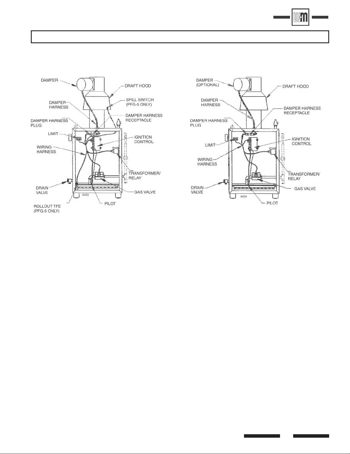
1. Bring supply wiring to boiler. Must be 14 ga. or heavier. See pages listed below each Figure for appropriate wiring diagram.
2. Proceed to page 6.
PFG 5 Boiler
Figure 1,
see page 4
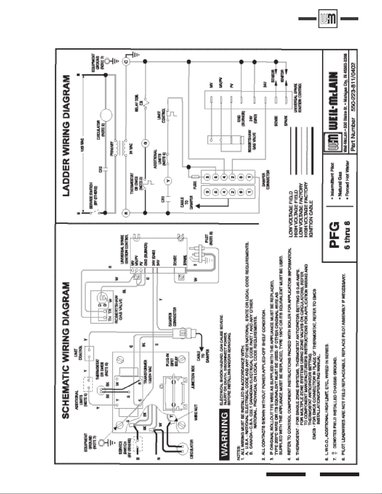
PFG 6 thru 8 Boilers
Figure 2,
see page 5
Part Number 550-110-643/0605
3
Page 4
PFG SerieS 7 GaS-Fired Water Boiler – UniverSal Control SyStemS
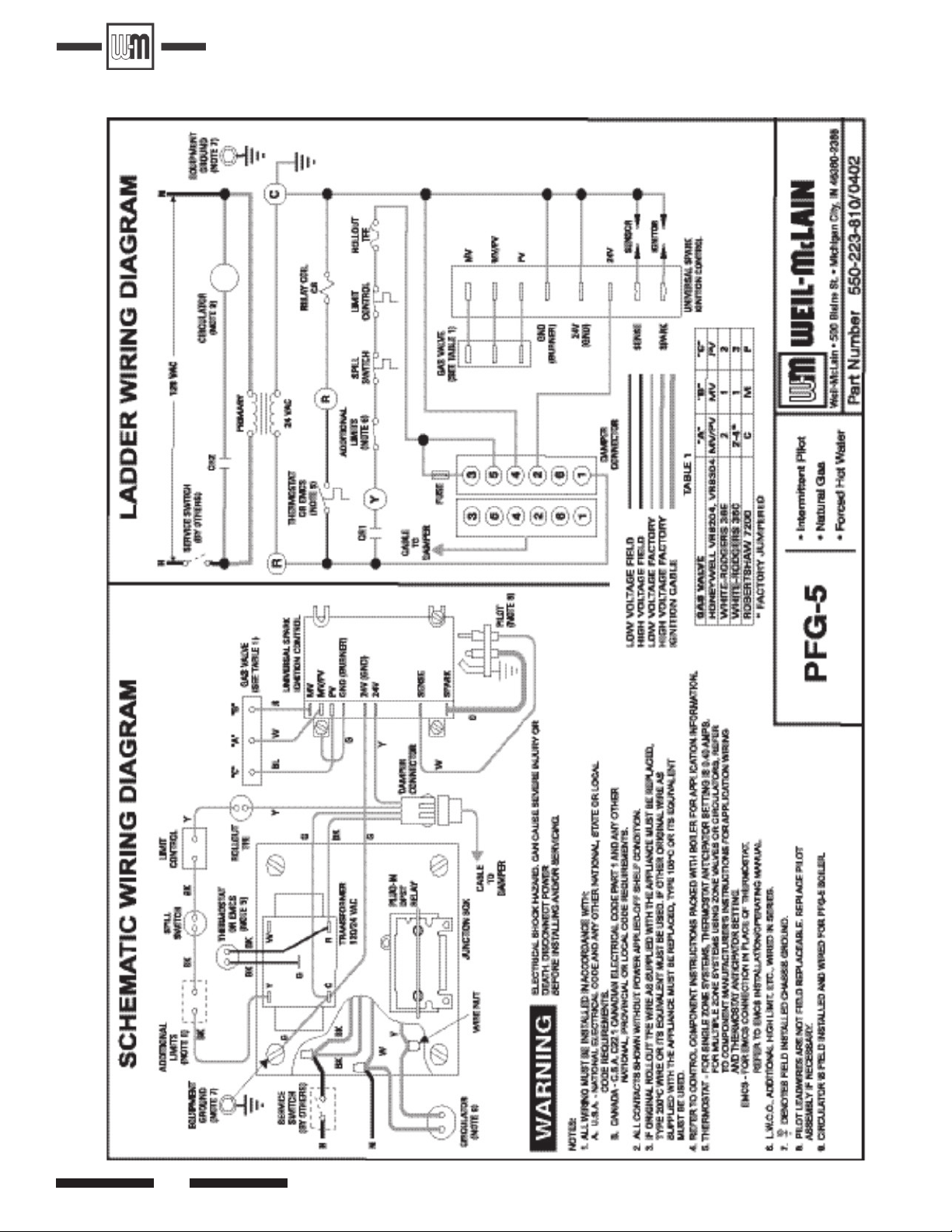
PFG-5
4
Part Number 550-110-643/0605
Page 5
PFG SerieS 7 GaS-Fired Water Boiler – UniverSal Control SyStemS
PFG 6 thru 8
Part Number 550-110-643/0605
5
Page 6

PFG SerieS 7 GaS-Fired Water Boiler – UniverSal Control SyStemS
These boilers must have vent dampers:
• PFG 5 (U.S. only)
These boilers may have vent dampers:
• PFG 6-8 (U.S. only)
• PFG 5-7 (Canadian)
These boilers must not have vent damper:
• PFG 8 (Canadian)
If not installing damper, proceed to page 7.
1.
Only dampers listed on page 16 are
2. Efkal and Johnson dampers - install plug (packed in damper
carton of 4” thru 8” dampers) in hole in damper blade.
3. Minimum clearances:
Once damper is installed on boiler,
boiler will not operate without
damper installed.
approved for use on PFG Series 6 &
7 boilers. Any other damper installed
can cause severe personal injury or
death.
Section B: Damper Installation
Where screws or rivets are used to secure damper to draft
hood, they must not interfere with free movement of damper
blade.
5. Install damper harness between damper actuator and knock-
out in jacket top panel. Use strain relief connectors and
locknuts to secure both ends of damper harness. See Figure
1 or 2.
Keep wiring harness clear of all hot
surfaces.
PFG - 48” between jacket top and combustible ceiling.
DO NOT modify draft hood or
damper, or make another connection
between draft hood and damper
or boiler. This will void C.S.A.
certication and will not be covered
by Weil-McLain warranty. Any
changes will cause severe personal
injury, death or substantial property
damage.
4. PFG - Damper must be installed directly on top of draft
hood so that it serves only one boiler and so that damper
blade indicator is visible to homeowner. See Figure 1 or 2
and Figure 3 or 4.
6. Remove dummy receptacle from damper plug in boiler wiring
harness. Plug damper harness receptacle into damper harness
plug. See Figure 1 or 2.
Bypassing (jumpering) damper will
cause ue products such as carbon
monoxide to escape into house. This
will cause severe personal injury or
death.
After boiler has operated once, if
either end of harness is disconnected,
system shutdown will occur. Boiler
will not operate until harness is
reconnected.
7. Efkal damper - damper “Hold Open” switch must be in “Au
tomatic Operation” position for system to operate properly.
8. Apply label shown in step 5 to damper, so that it is visible
after installation.
9. Proceed to page 7.
-
Efkal Damper
Figure 3
6
Johnson Damper
Figure 4
Part Number 550-110-643/0605
Page 7

PFG SerieS 7 GaS-Fired Water Boiler – UniverSal Control SyStemS
Section C: Check-Out
1. See Figure 5 for operating instructions page numbers. Raise
room thermostat to call for heat. Damper actuator will slowly
open damper (if provided).
2. When damper (if provided) is fully open, ignition control
powers spark generator and opens pilot valve.
Damper must be in open position when
appliance main burners are operating.
If damper is not in open position, ue
products will escape into house, causing
severe personal injury or death.
3. a. If pilot does not light within 15 seconds, pilot valve is closed
and spark generator is turned off. The ignition control initi-
ates a ve minute wait period. If call for heat exists after
ve minutes, ignition sequence starts at Step 2.
b. If pilot lights and ignition control senses ame current,
main valve opens and spark generator is turned off.
Figure 5
4. During main burner operation:
a. Ignition control monitors pilot ame current. If signal is
lost, main valve is closed, spark generator activated, and
sequence returns to Step 3.
b. If power is interrupted, the control system shuts off pilot
and main gas valves and restarts at Step 1 when power is
restored.
5. Thermostat is satised: pilot and main gas valves are closed.
Damper (if provided) will close.
6. Boiler is now in the off cycle.
7. Repeat steps 1-6 several times to verify operation.
8. Return thermostat to normal setting.
9. Set thermostat heat anticipator setting indicated in notes on
wiring diagram.
Part Number 550-110-643/0605
7
Page 8

PFG SerieS 7 GaS-Fired Water Boiler – UniverSal Control SyStemS
PFG-5 WITH HONEYWELL VR8204/VR8304 GAS VALVE
8
Part Number 550-110-643/0605
Page 9

PFG SerieS 7 GaS-Fired Water Boiler – UniverSal Control SyStemS
PFG-5 WITH WHITE-RODGERS 36C GAS VALVE
Part Number 550-110-643/0605
9
Page 10

PFG SerieS 7 GaS-Fired Water Boiler – UniverSal Control SyStemS
PFG 6-8 WITH ROBERTSHAW 7000 DERHC GAS VALVE
10
Part Number 550-110-643/0605
Page 11

PFG SerieS 7 GaS-Fired Water Boiler – UniverSal Control SyStemS
Section D: Troubleshooting
VERIFY PROPER OPERATION AFTER SERVICING
Never jumper (bypass) any device except
for momentary testing as outlined in
Troubleshooting Charts. Substantial
property damage and/or severe personal
injury could occur.
Label all wires prior to disconnection
when servicing controls. Wiring errors
can ca use improper and dan gerous
operation.
1. Before troubleshooting.
a. Have a voltmeter that can check 120VAC, 24VAC, a
microammeter with minimum scale range of 0-25, and a
continuity tester.
b. Check for 120VAC (min. 102 - max. 132) to boiler.
c. Check for 24VAC at secondary side of transformer.
d. Make sure thermostat is calling for heat and contacts
(including appropriate zone controls) are closed. Check for
24VAC between thermostat wire nuts and ground.
IN EVENT OF ACTUATOR FAILURE
–EFFIKAL DAMPER
If troubleshooting chart recommends replacing actuator, and
actuator is not immediately available, damper blade can be
xed in an open position to allow boiler operation.
Manually turning blade can cause actuator damage. Follow these
instructions only in case of no heat or damper actuator malfunc-
tion. See Figure 6.
1. Move damper service switch to “HOLD DAMPER OPEN”
position. Apply “call for heat” to boiler. Damper blade should
then rotate to open position and boiler will re.
2. If Step 1 above does not open damper, manually rotate
damper blade to open position using wrench or pliers on at
shaft between damper and actuator. Boiler will re. Verify
that damper service switch is in “HOLD DAMPER OPEN”
position.
3. Do not leave damper permanently in this position. Replace
actuator immediately. If damper is left in open position, boiler
will not operate at published efciencies.
Figure 6
JOHNSON DAMPER
If troubleshooting chart recommends replacing actuator, and
actuator is not immediately available, damper blade can be xed
in open position to allow boiler operation. Follow these instruc-
tions only in case of no heat or damper actuator malfunction.
See Figure 7.
1) Turn off power to boiler.
Failure to turn off power to boiler can result
in severe personal injury, death or substantial
property damage.
2) Remove damper actuator cover.
3) On PC board, move wire from A to B.
4) Turn on power to boiler.
5) Using wrench or pliers on at shaft section, manually rotate
damper blade until green light turns on. Boiler will re.
6) Do not leave damper permanently in this position. Replace
actuator immediately. If damper is left in open position, boiler
will not operate at published efciencies.
See damper manufacturer’s instructions packed with
damper for additional information.
See damper manufacturer’s instructions packed with
damper for additional information.
Part Number 550-110-643/0605
Figure 7
11
Page 12

Check for open thermostat or circ. relay
(where used) or check for loose wire
connections, defective spill switch or
rollout thermal fuse element, or open
LWCO or limit contacts.
If LWCO, spill switch or
rollout thermal fuse element
contacts are open, determine cause
and correct condition. Failure to do so
will cause severe personal injury, death,
or substantial property damage.
Open thermostat contacts for 15 seconds. Close thermosta t
contacts - is 24 VAC across terminals PV & MV/PV?
No Yes
Replace ignition control.
Is 24VAC present across Terminals 24V & 24V(GND)?
No Yes
VISUALLY CHECK - is ground wire connected from
"GND(Burner)" to ignition control mounting screw;
and ground wire connected from transformer
Terminal "C" to case ground?
No Yes
Correct by making connections.
Turn
OFF
supply voltage.
Check spark wire. Is it securely connected
to spark transformer?
No Yes
Securely connect, then turn ON supply voltage and re-test.
Is condition of spark wire good (not cut,
brittle, burned, or cracked)?
No Yes
Is spark gap 0.125" and isolated in pilot gas steam?
No Yes
Replace pilot assembly.
Replace pilot assembly, turn ON supply
voltage, operate system several complete
heat cycles.
Replace ignition control.
Replace pilot assembly, turn ON supply
voltage, operate system several
complete heat cycles.
TABLE I: No Spark, System Does Not Work
Without Vent Damper
Is spark electrode ceramic cracked?
No Yes
PFG SerieS 7 GaS-Fired Water Boiler – UniverSal Control SyStemS
12
Part Number 550-110-643/0605
Page 13

PFG SerieS 7 GaS-Fired Water Boiler – UniverSal Control SyStemS
Check for open thermostat or circ. relay (where used) or check for
loose wire connections, defective spill switch or rollout thermal fuse
element, or open LWCO or hight limit contacts.
If LWCO, spill switch or rollout thermal fuse element
contacts are open, determine cause and correct
condition. Failure to do so will cause severe personal injury, death,
or substantial property damage.
Is damper harness securely plugged in at both
ends?
No
Yes
Secure connections.
TABLE II: No Spark, System Does Not Work
With Vent Damper
Is 24VAC present across terminals C and Y on
transformer?
No Yes
Check for loose wire connections
or bad relay on transformer.
Is 24VAC present across terminal C and yellow wire
between damper connector and rollout thermal fuse
element?
No Yes
Replace actuator.
Check for out of round stack section.
Does motor rotate open?
No Yes
Is damper rotated open?
No Yes
Open thermostat contacts for 30
seconds. Damper will rotate to closed
position. Close thermostat contacts.
Damper will rotate to open position..
Is 24VAC present across terminals PV
and MV/PV?
No Yes
Is 24VAC present at Terminals
PV and MV/PV?
No Yes
Is spark present now?
Yes No
Re-test.
Turn
OFF
supply voltage.
Check continuity of each wire in wiring
harness to damper. Does continuity exist
for each wire?
No Yes
Replace damper
wiring harness.
Securely connect and
turn ON supply voltage.
Re-test.
Check spark wire. Is it securely
connected to ignition control?
No Yes
Is condition of spark
wire good (not brittle,
burned or cracked)?
No Yes
Remove damper harness from boiler
wiring harness. TEMPORARILY install
jumper between terminal 2 and
terminal 5 on damper plug in boiler
wiring harness. See Figure 10. Does
boiler fire?
No Yes
Replace pilot assembly.
Replace ignition control.
Replace actuator.
Is spark gap 0.125" and
located in pilot gas stream?
No Yes
Replace pilot assembly.
Replace ignition
control.
Is spark electrode ceramic
cracked?
No Yes
Replace pilot assembly.
Turn ON supply voltage
and operate system
several complete cycles.
Part Number 550-110-643/0605
13
Page 14

PFG SerieS 7 GaS-Fired Water Boiler – UniverSal Control SyStemS
TABLE III: Pilot Lights, Main Valve Will Not Come On
With or Without Vent Damper
Correct wiring.
Make sure sense wire is not wrapped
around any pipe or accessories.
Is sense wire securely attached to sense
terminal and pilot assembly?
No Yes
Correct.
Replace pilot
assembly.
Replace
valve.
Check for continuity of sense wire
and condition of insulation.
Not OK OK
Check for proper gas pressure, clean pilot assembly
tight mechanical and electrical connections.
Also check for proper system grounding.
See additional information on page 15.
Does spark stay on for more than a few seconds after pilot is established?
No
Yes
Is sensing probe ceramic
cracked?
No Yes
Replace pilot
assembly.
Is sense wire or sensing
probe shorted out to
metal surface?
No Yes
Correct.
Replace ignition control.
Replace ignition
control.
Is 24VAC between Terminals
MV and MV/PV on ignition control?
No Yes
Contact gas supplier to
correct.
Is inlet gas pressure at least
5.0"W.C. and not over
14"W.C.?
No
Yes
Is main valve wiring secure
at terminals?
No Yes
No
Yes
Does system have proper flame signal?
Set up microammeter to measure
output current in flame sensor circuit
as follows:
a. Detach sense lead from ignition
control. Attach negative lead
from microammeter to sense
terminal on ignition control.
b. Attach positive lead to sense wire
from pilot assembly.
c. Disconnect main valve lead from
Terminal "MV" on ignition control.
d. Energize the system. Spark should
ignite the pilot. As soon as pilot is
burning, microammeter should
read at least 1.0 microamp for
Honeywell S8620C, 0.1 microamp
for U.T. 1003-510.
e. Is flame current signal less than the
minimum specified in "d" above?
14
Part Number 550-110-643/0605
Page 15

PFG SerieS 7 GaS-Fired Water Boiler – UniverSal Control SyStemS
TABLE IV: Spark is Present, Pilot Will Not Light
With or Without Vent Damper
Connect securely to Terminals PV
and MV/PV on ignition control.
Are pilot valve connections CORRECT and securely fastened?
No
Yes
Open manual hand valve.
Is manual hand valve open?
No Yes
Is inlet gas pressure at least 5.0"W.C. and not over 14.0"W.C.?
No Yes
Contact gas supplier to
correct gas pressure.
Is gas present at pilot burner assembly? CAUTION Remove MV wire from ignition control, use a match
taped to a long screwdriver or pilot lighter rod and
manually light pilot.
No Yes
Make sure gas cock is in "ON" position and pilot line is
not kinked or obstructed. Check for clean pilot orifice.
If OK, replace gas valve.
Replace pilot assembly.
Block any draft around boiler. Check for clean pilot orifice.
Is spark gap 0.125" and located in pilot gas stream?
No Yes
TO CHECK IGNITION SYSTEM GROUNDING FOR TABLE III, PAGE 14.
Nuisance shutdowns are often caused by poor or erratic ground.
• Check for good metal-to-metal contact between pilot burner bracket
and main burner, and between main burner and burner rest.
control mounting screw, and from "C" on transformer to transformer case ground.
Make sure connections are clean and tight. If wire is damaged or deteriorated,
replace with No. 18 ga. moisture-resistant, thermosplastic insulated wire with
105°C minimum rating.
• Check ground lead from GND (BURNER) terminal on ignition control to ignition
Pilot assembly and ignition control must share common ground with main burner.
Part Number 550-110-643/0605
15
Page 16

Section E: Parts
Part Description Vendor Part Number W-M
Part No.
Damper Assembly
PFG-5)
8" (PFG-6)
9" (PFG 7-8)
Effikal RVGP-KS-7BKF
Johnson Q35GH-2 consisting of M35BC actuator and Y15 vent
pipe
Effikal RVGP-KS-8BFK
Johnson Q35GK-2 consisting of M35BC actuator and Y15 vent
pipe
Effikal RVGP-KS-9BF**
Johnson Q35GM-2 consisting of M35BC actuator and Y15 vent
pipe**
381-800-477
381-800-478
381-800-445
Damper Actuator Effikal RVGP (Effikal Only)
Johnson M35BE-1C (Johnson Only)
510-512-337
510-312-255
Damper Harness Weil-McLain 591-391-795
UCS Ignition Control Honeywell S8620C1003
United Technologies 1003-511
511-330-097
Pilot Burner Assembly Johnson Controls Q90GE-1 consisting of J981LYW pilot and
Y75AA-3 flame sensor
511-330-218
Boiler Wiring Harness, PFG-5
Boiler Wiring Harness, PFG 6-8
Weil-McLain
Weil-McLain
591-391-878
591-391-880
Gas Valve 3/4"
X
3/4"
PFG 5
Gas Valve 3/4"
X
1"
PFG 6-7
Gas Valve 1"
X
1"
PFG-8
Honeywell VR8304P4348
White-Rodgers 36C74-474
Robertshaw 7000 DERHC-S7C
Robertshaw 7000 DERHC-S7C
511-044-382
511-044-286
511-044-287
PFG SerieS 7 GaS-Fired Water Boiler – UniverSal Control SyStemS
**Not for use on Canadian PFG-8 boilers.
Only dampers listed above are approved for use on and PFG Series 6 & 7 boilers.
Any other damper installed can cause severe personal injury or death.
16
Part Number 550-110-643/0605
 Loading...