

Page 1
88
Water & Steam Boilers – Series 2
For Gas, Light Oil, & Gas/Light Oil – Fired Burners
Burner Specification
& Data Sheet
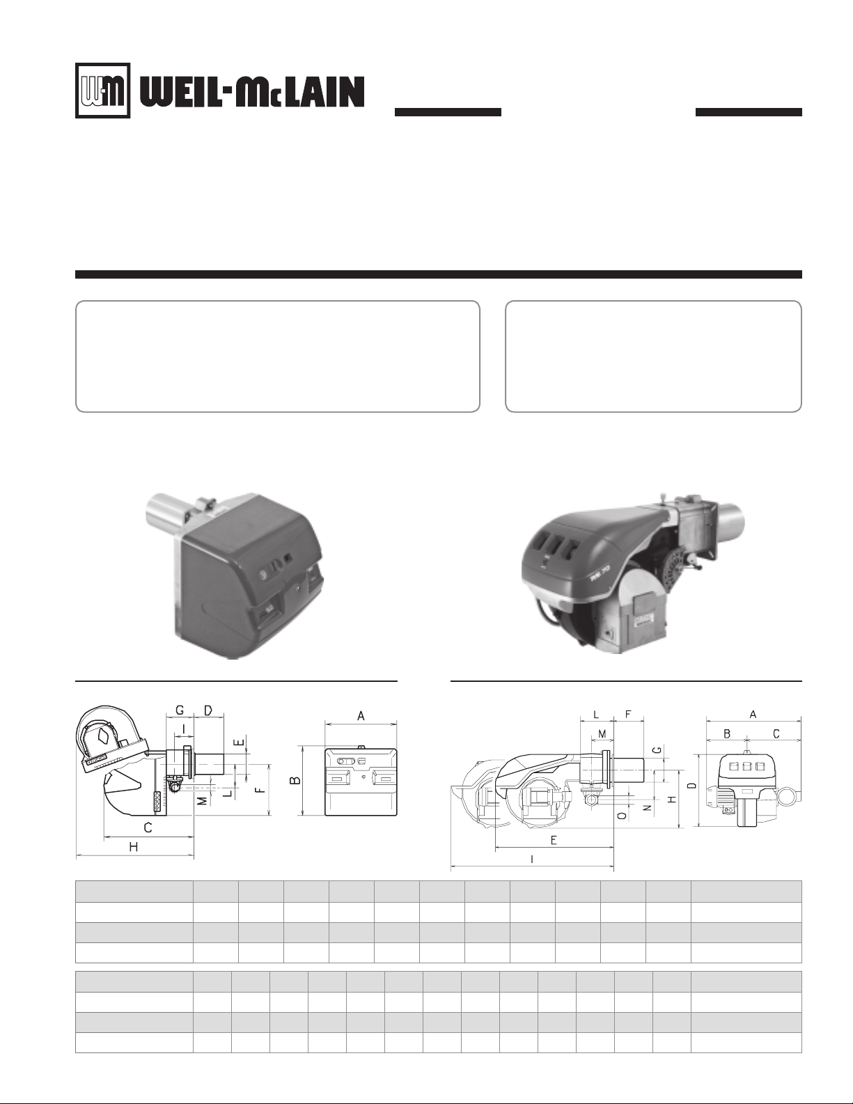
Model RLS28 – 50 dimensionsFigure 1 Model RLS70 – 190 dimensionsFigure 2
Riello
Gas/Oil Burners
Model RLS
Burner Model Number A B C D E F G H I L M Approx. Wt. (pounds)
RLS28 18.75 18.69 22.88 8.50 5.50 13.88 6.44 31.88 4.25 6.63 1.50 95
RLS38 18.75 18.69 22.88 8.50 5.50 13.88 6.44 31.88 4.25 6.63 1.50 99
RLS50 18.75 18.69 22.88 8.50 5.50 13.88 6.44 31.88 4.25 6.63 1.50 101
Burner Model Number
RLS70 27.50 11.38 16.13 21.88 33.13 9.88 7.06 16.94 45.75 8.44 5.31 8.75 2.00 159
RLS100 28.88 12.75 16.13 21.88 33.13 9.88 7.06 16.94 45.75 8.44 5.31 8.75 2.00 165
RLS130 28.88 12.75 16.13 21.88 33.13 9.88 7.44 16.94 45.75 8.44 5.31 8.75 2.00 170
ABCDEFGH I LMNO
Part No. 550-142-023/0508
Approx. Wt. (pounds)
Page 2
Weil-McLain 88 Water and Steam Boilers — Series 2 — For Gas, Light Oil, & Gas/Light Oil-Fired Burners
Burner specifications and settings
Burner data — #2 Fuel oil/Natural gas — ModulatingTable 1
Boiler
Burner
Pressure
Manifold
Model
Model
Number
Drop Thru
Gas Train
Inches
W.C.
Number
488R RLS28 1.19 4.60 5.79 14 5.0 1 23 67 22 42 70 — — — — — —
488 RLS28 1.19 4.85 6.04 14 5.0 2 23 67 22 42 70 — — — — — —
588 RLS38 1.88 5.85 7.73 14 5.0 1 20 50 19 41 55 — — — — — —
688 RLS50 2.09 5.88 7.97 14 5.0 3 32 90 32 50 90 — — — — — —
788 RLS50 2.12 5.85 7.97 14 5.0 5 35 83 35 45 83 — — — — — —
888 RLS70 3.04 4.36 7.40 14 7.5 0 1.5 6.0 — — — 130 0 40 120 30 100
988R RLS70 3.18 4.14 7.32 14 7.5 0 1.8 7.5 — — — 130 0 40 120 27 100
988 RLS70 3.18 4.39 7.57 14 7.5 1 1.8 7.5 — — — 130 0 40 120 27 100
1088R RLS70 3.35 3.68 7.03 14 7.5 3 1.9 9.0 — — — 130 0 32 120 45 100
1088 RLS100 3.35 3.93 7.28 14 7.5 4 1.9 9.0 — — — 130 0 32 120 45 100
1188 RLS100 3.55 4.45 8.00 14 6.0 4 2.2 5.2 — — — 130 0 30 120 35 100
1288 RLS100 2.60 5.30 7.9 14 6.0 4 2.0 6.0 — — — 130 0 30 120 40 100
1388 RLS100 3.35 4.65 8.00 14 6.0 9 2.0 6.5 — — — 130 0 30 120 40 100
1488 RLS130 2.81 4.54 7.35 14 6.0 6 2.0 6.0 — — — 130 0 40 120 55 100
1588 RLS130 2.99 4.65 7.64 14 5.5 7 2.5 7.0 — — — 130 0 40 120 30 100
1688R RLS130 3.40 4.85 8.25 14 5.0 8 2.5 8.0 — — — 130 0 40 120 30 100
1688 RLS130 3.40 5.10 8.5 14 5.0 9 2.0 9.0 — — — 130 0 50 120 30 100
Pressure
Inches
W.C.
Gas Pressure
Required at
Gas Control
Inches
W.C.
Min
Inlet
Inches
W.C.
Max
Gas Pilot
Pressure
Inches
W.C.
Combustion
Head
Setting
Combustion
Air
Indications
Low
High
Fire
Fire
Servo Motor Cam
Position Settings
Blue Orange Red 1 2 3 4 5 6 Qty. GPH
@ 100
PSIG
112.75
2.50
113.00
2.50
114.00
3.50
114.50
5.00
115.50
6.00
116.50
6.50
117.50
7.25
117.50
7.50
118.50
7.25
118.50
7.50
9.00
1
1
9.00
1110.00
10.00
1111.00
11.00
1112.00
12.00
1112.00
12.00
1113.00
12.50
1113.00
13.00
Oil
Nozzles
Brand Type Spray
Delavan B
Delavan B
Delavan B
Delavan B
Delavan B
Delavan B
Delavan B
Delavan B
Delavan B
Delavan B
Delav
an B
Delavan B
Delavan B
Delavan B
Delavan B
Delavan B
Delavan B
Pressure
Supply
Angle
70°
60°
70°
60°
60°
60°
60°
60°
60°
80°
90°
60°
90°
60°
60°
60°
60°
60°
60°
60°
60°
60°
60°
60°
60°
60°
60°
60°
60°
60°
60°
60°
60°
60°
Oil
PSIG
180 AL65C 22.0
180 AL65C 22.0
167 AL65C 22.0
173 AL65C 22.0
168 AL65C 22.0
180 AJ4CC 52.5
180 AJ4CC 52.5
180 AJ4CC 52.5
209 AJ4CC 52.5
209 AJ4CC 52.5
180 AJ4CC 52.5
180 AJ4CC 52.5
200 AJ4CC 52.5
200 AJ4CC 52.5
220 AJ4CC 52.5
215 AJ4CC 52.5
215 AJ4CC 52.5
Fuel
Independent
Motor Driven
3450 RPM
Suntec
Gear
Type
GPH
Notes for Table 1, Table 2 and Table 3
Burner capacities listed for elevations up to 2,000 feet. For higher eleva-1.
tions, consult local Weil-McLain distributor/ agent or sales office.
Light oil ratings based on No. 2 fuel oil with heating value of 140,000 2.
Btu per gallon.
Gas ratings based on natural gas with heating value of 1,000 Btu per cubic 3.
foot and specific gravity of 0.60. Gas burners for other gases are available.
Consult local Weil-McLain distributor/agent or sales office.
Boiler-burner unit to be adjusted to achieve +0.10 inches W.C. pressure at 4.
the flue collar, resulting in positive pressure in firebox as listed.
Minimum gas pressures listed are subject to variations due to job condi-5.
tions. Gas burners for other gas pressures are available. Consult local
Weil-McLain distributor/agent or sales office.
All gas train sizes shown are based on a supply pressure to the regulator of 6.
7 inches w.c. Optional trains available for other pressures upon request.
All Settings and pressures shown are for initial start-up. Final values should 7.
be confirmed with combustion analysis.
Gas/Light Oil control Systems: 8.
LHL: Low-high-low-off firing conditions – two position air and fuel •
controlled by separate motor, open damper pre-purge.
MOD: On-off operation with proven low fire start and full modu-•
lating firing conditions. Proportional motor drives fuel metering
valve and combustion air damper according to firing conditions;
open damper pre-purge.
120/60/1 control circuit is used for all burners.9.
All 3 phase models require a separate 12/60/1 control voltage supply.10.
Burner settings shown are for initial start-up. Follow burner manual to 11.
adjust burner using combustion test instruments as directed.
120/60/1 control circuit is used for all burners.12.
488R to 788 units require a single SPDT controller for LHL firing rate 13.
operation on both fuels.
888 to 1688 units require a 4 – 20mA 0 – 10vdc or 135 ohm signal for 14.
modulation on gas plus a SPDT controller for LHL firing rate operation
on oil.
Motor relay or contactor is standard on all units.15.
Combustion Controls:16.
Siemens LFL 1.335 flame safeguard control monitors the oil or gas •
burner flame with visual diagnostic window, provides pre-purge and
post purge, provides switching necessary to allow firing rate motor to
2 Part No. 550-142-023/0508
Page 3

Burner Specification & Data sheet — Riello Gas/Oil Burners
Burner specifications and settings (continued)
Burner data — #2 Fuel oil/Natural gas — ModulatingTable 2
Boiler Model
Number
488R 6.90 996 0.89 RLS28 LFL 1.335 LHL/LHL 1/2 120/60/1
488 7.00 1010 1.00 RLS28 LFL 1.335 LHL/LHL 1/2 120/60/1
588 9.40 1357 0.84 RLS38 LFL 1.335 LHL/LHL 1/2 120/60/1
688 11.80 1703 0.72 RLS50 LFL 1.335 LHL/LHL 3/4 3 phase*
788 14.20 2049 0.65 RLS50 LFL 1.335 LHL/LHL 3/4 3 phase*
888 16.60 2396 0.85 RLS70 LFL 1.335 MOD/LHL 1 1/2 3 phase*
988R 17.20 2482 0.80 RLS70 LFL 1.335 MOD/LHL 1 1/2 3 phase*
988 18.80 2713 0.80 RLS70 LFL 1.335 MOD/LHL 1 1/2 3 phase*
1088R 20.00 2887 0.82 RLS70 LFL 1.335 MOD/LHL 1 1/2 3 phase*
1088 21.50 3103 0.82 RLS100 LFL 1.335 MOD/LHL 2 1/2 3 phase*
1188 23.50 3392 0.82 RLS100 LFL 1.335 MOD/LHL 2 1/2 3 phase*
1288 26.00 3753 0.81 RLS100 LFL 1.335 MOD/LHL 2 1/2 3 phase*
1388 28.50 4113 0.89 RLS100 LFL 1.335 MOD/LHL 2 1/2 3 phase*
1488 31.00 4474 0.86 RLS130 LFL 1.335 MOD/LHL 3 3 phase*
1588 33.00 4763 0.86 RLS130 LFL 1.335 MOD/LHL 3 3 phase*
1688R 34.50 4979 0.863 RLS130 LFL 1.335 MOD/LHL 3 3 phase*
1688 35.50 5124 0.83 RLS130 LFL 1.335 MOD/LHL 3 3 phase*
Burner Input Positive
No. 2 Oil Gas
GPH MBH Inches W.C Note 16 Gas/Oil H.P.
Pressure in
Firebox
Standard Burner
Model Designation
Standard
Combustion
Control
*208/60/3, 240/60/3, 480/60/3, 575/60/3 burner motor voltage must be specified
Standard Control
System
Burner Motor
3400 RPM
Standard Motor
Voltage
Gas control components and sizesTable 3
Boiler
Model
Number
488R – 588
688 – 1088
1188 – 1288
1388 – 1688
Manual
Hand Valve
Inches Inches Inches Inches Inches
1 1/2 Standard 1 1/2 1 1/2 Optional 1 1/2 1 1/2 Standard
2 Standard 2 2 Optional 2 2 Standard
2 1/2 Standard 2 1/2 2 1/2 Optional 2 1/2 2 1/2 Standard
3 Standard 3 3 Optional 3 3 Standard
Low Gas
Pressure Switch
Gas
Pressure Regulator
Notes for Table 1, Table 2 and Table 3 (continued)
be driven to both low fire and high fire positions, prevent start up if
pre-ignition interlocks are open and has low fire start proven circuit.
In the event pre-ignition interlock circuit or running interlock circuit
does not “prove”, system will lock out on safety. Ultra violet sensitive
electronic flame detector is standard.
Other flame safeguards available upon request.17.
Control circuit transformer is available as an option.18.
Airflow safety switch is standard for all gas and combination gas/light 19.
oil units.
Burners will be completely assembled and wired (except gas train) and 20.
factory test-fired.
Operating
Gas Valve
Operating Gas
Valve (with Proof Of
Closure)
Safety
Gas Valve
Manual
Checking Gas Valve
High Gas
Pressure Switch
Burners listed by Underwriters Laboratories, Inc., state of Connecticut, Fire 21.
Marshal state of Massachusetts, city of New York MEA, and others.
Special controls can be provided to meet other code requirements not listed. 22.
Consult your local Weil-McLain distributor/agent or sales office.
Electric gas pilot will be furnished as standard equipment on all combina-23.
tion gas/light oil units.
Direct spark ignition is available as an option for combination gas/light oil 24.
units. Consult your local Weil-McLain distributor/agent or sales office.
3Part No. 550-142-023/0508
Page 4

Weil-McLain 88 Water and Steam Boilers — Series 2 — For Gas, Light Oil, & Gas/Light Oil-Fired Burners
4 Part No. 550-142-023/0508
 Loading...