


MVW3000 A0040 V023
WEG MVW3000 A0040 V023, MVW3000 A0050 V023, MVW3000 A0090 V023, MVW3000 A0080 V023, MVW3000 A0100 V023 User Manual
...
User's Manual
Series: MVW3000
Language: English
Document: 10004823674 / 00
Please take this page out when
unpacking the product
13941741


Motors I Automation I Energy I Transmission & Distribution I Coatings
Medium Voltage Frequency Inverter
MVW3000
User's Manual


User’s Manual
Series: MVW3000
Language: English
Document: 10004823674 / 00
Publication Date: 03/2017

Summary of Reviews
Vers ion Review Description
- R00 First edition

Contents
1 SAFETY NOTICES ................................................................................1-1
1.1 SAFETY NOTICES IN THE MANUAL .........................................................................................1-1
1.2 SAFETY NOTICES ON THE PRODUCT .....................................................................................1-1
1.3 PRELIMINARY RECOMMENDATIONS ......................................................................................1-2
2 GENERAL INFORMATION ................................................................... 2-1
2.1 ABOUT THIS MANUAL ...............................................................................................................2-1
2.2 MVW3000 IDENTIFICATION LABEL ..........................................................................................2-2
2.3 RECEIVING AND STORAGE.......................................................................................................2-2
2.4 HOW TO SPECIFY THE MVW3000 MODEL ..............................................................................2-3
2.4.1 Available Models ...............................................................................................................2-5
3 PRODUCT CHARACTERISTICS .........................................................3-1
3.1 INPUT TRANSFORMER .............................................................................................................3-1
3.2 POWER CELLS ...........................................................................................................................3-3
3.3 CONNECTION OF THE CELLS ..................................................................................................3-5
3.4 CONTROL ....................................................................................................................................3-8
4 TECHNICAL DATA ..............................................................................4-1
4.1 MVW3000 PANEL ........................................................................................................................4-1
4.1.1 Panel Constructive Aspects .............................................................................................4-2
4.2 POWER CELLS ...........................................................................................................................4-4
4.2.1 Constructive Aspects .......................................................................................................4-4
4.2.2 Power Cell Boards and Connections ..............................................................................4-6
4.3 CONTROL RACK ........................................................................................................................4-6
4.4 OUTPUT FILTERS .......................................................................................................................4-7
5 SYNCHRONOUS MOTOR LINE ..........................................................5-1
5.1 ABSOLUTE ENCODER WITH RSSI BOARD .............................................................................5-1
5.1.1 Absolute Encoder ..............................................................................................................5-1
5.1.2 RSSI Board .........................................................................................................................5-2
5.2 FIELD EXCITATION SET (DC WITH BRUSHES) ........................................................................5-4
6 INSTALLATION, CONNECTION AND ENERGIZATION ......................6-1
6.1 MECHANICAL INSTALLATION ..................................................................................................6-1
6.1.1 Environmental Conditions ................................................................................................6-1
6.1.2 Handling Recommendations ............................................................................................6-2
6.1.3 Hoisting ..............................................................................................................................6-2
6.1.4 Moving ...............................................................................................................................6-3
6.1.5 Unpacking ..........................................................................................................................6-3
6.1.6 Positioning/Mounting........................................................................................................6-4
6.1.7 Insertion of the Power Cells .............................................................................................6-6
6.1.8 Electrical and Fiber Optic Connections on the Power Cells .........................................6-8
6.2 ELECTRICAL INSTALLATION ....................................................................................................6-10
6.2.1 Power Section ...................................................................................................................6-10
6.2.2 Input Cubicle ......................................................................................................................6-12
6.2.3 Low Voltage Auxiliary Supply ...........................................................................................6-13
6.3 ENERGIZATION, START-UP AND SAFE DE-ENERGIZATION .................................................6-14
6.3.1 Pre-power Checks ............................................................................................................6-14
6.3.2 Initial Power-up (Parameter Settings) ............................................................................6-15
6.3.3 Start-up .............................................................................................................................6-15
6.3.3.1 Start-up with HMI Operation and V/F 60 Hz Control Mode ................................6-15
6.3.4 Safe De-energization Instructions ...................................................................................6-17

Contents
7 OPTIONAL ACCESSORIES AND BOARDS ........................................ 7-1
7.1 MVC4 SIGNAL AND CONTROL CONNECTIONS .....................................................................7-1
7.2 FUNCTION EXPANSION BOARDS ............................................................................................7-5
7.2.1 EBA (I/O Expansion Board A) ...........................................................................................7-5
7.2.2 EBB (I/O Expansion Board B) ...........................................................................................7-9
7.2.3 PLC2 ...................................................................................................................................7-12
7.3 INCREMENTAL ENCODER ........................................................................................................7-14
7.3.1 EBA/EBB Boards ...............................................................................................................7-14
7.3.2 EBC1 Board .......................................................................................................................7-16
7.4 SHORT UPS MODULE ................................................................................................................7-19
7.4.1 CFW10 Inverter Parameterization....................................................................................7-19
7.5 MVC3 CONTROL BOARD CONNECTIONS...............................................................................7-20
8 SPECIAL FUNCTIONS ......................................................................... 8-1
8.1 LOAD SHARE FUNCTION “MASTER/SLAVE” ..........................................................................8-1
8.2 SYNCHRONOUS TRANSFER FUNCTION .................................................................................8-3
8.3 CELL BYPASS .............................................................................................................................8-5
8.4 ANGLE ADJUSTMENT ...............................................................................................................8-6
9 COMMUNICATION NETWORKS ......................................................... 9-1
9.1 FIELDBUS KIT .............................................................................................................................9-1
9.1.1 Installation of the Fieldbus Kit .........................................................................................9-1
9.1.2 Profibus DP ........................................................................................................................9-2
9.1.3 DeviceNet ...........................................................................................................................9-5
9.1.4 DeviceNet Drive Profile .....................................................................................................9-7
9.1.5 Ethernet ..............................................................................................................................9-7
9.1.6 Fieldbus Application/MVW3000 Related Parameters ....................................................9-7
9.1.6.1 Variables Read From the Inverter .........................................................................9-8
9.1.6.2 Variables Written in Inverter ..................................................................................9-9
9.1.6.3 Error Indications .....................................................................................................9-11
9.1.6.4 MVW3000 Variable Addressing at the Fieldbus Devices ....................................9-12
9.2 WEGBUS SERIAL ........................................................................................................................9-12
9.2.1 Protocol Definitions ..........................................................................................................9-15
9.2.2 Variable Code ....................................................................................................................9-17
9.2.3 MVW3000 Special Parameters .........................................................................................9-21
9.2.4 RS-232 and RS-485 Physical Connection .......................................................................9-23
9.3 MODBUS-RTU ............................................................................................................................9-24
9.3.1 Introduction to the Modbus-RTU Protocol .....................................................................9-24
9.3.1.1 Transmission Modes ..............................................................................................9-24
9.3.1.2 RTU Mode Message Structure ..............................................................................9-25
9.3.2 Operation of the MVW3000 in the Modbus-RTU Network .............................................9-26
9.3.3 Detailed Description of the Functions .............................................................................9-30
9.3.3.1 Function 01 - Read Coils .......................................................................................9-30
9.3.3.2 Function 03 - Read Holding Register ...................................................................9-31
9.3.3.3 Function 05 - Write Single Coil .............................................................................9-32
9.3.3.4 Function 06 - Write Single Register ......................................................................9-32
9.3.3.5 Function 15 - Write Multiple Coils ........................................................................9-33
9.3.3.6 Function 16 - Write Multiple Registers .................................................................9-34
9.3.3.7 Function 43 - Read Device Identification .............................................................9-34
9.3.4 ModBus RTU Communication Error ................................................................................9-36
MVW3000 | 1-1
11
Safety Notices
1 SAFETY NOTICES
This manual contains the necessary information for the correct use of the MVW3000 frequency inverter.
It has been written for qualified personnel with suitable training or technical qualifications to operate this type of
equipment.
This manual presents all the functions and parameters of the MVW3000. However, it is not intended to present
all the possible applications of the MVW3000. WEG will not take any liabilities for applications not described in
this manual.
1.1 SAFETY NOTICES IN THE MANUAL
Throughout this manual the following safety notes are used:
DANGER!
The procedures recommended in this warning have the purpose of protecting the user against dead,
serious injuries and considerable material damage.
DANGER!
Les procédures concernées par cet avertissement sont destinées à protéger l’utilisateur contre des
dangers mortels, des blessures et des détériorations matérielles importantes.
ATTENTION!
The procedures recommended in this warning have the purpose of avoiding material damage.
NOTE!
The text intents to supply important information for the correct understanding and good operation
of the product.
1.2 SAFETY NOTICES ON THE PRODUCT
The following symbols are attached to the product, serving as safety notices:
High voltages are present.
Components sensitive to electrostatic discharge.
Do not touch them.
Mandatory connection to the protective ground (PE).
Connection of the shield to the ground.
Hot surface.
1-2 | MVW3000
1
Safety Notices
1.3 PRELIMINARY RECOMMENDATIONS
DANGER!
Only qualified personnel familiar with the MVW3000 frequency inverter and associated equipment
should plan or implement the installation, start-up and subsequent maintenance of this equipment
These personnel must follow all the safety instructions included in this manual and/or defined by local
regulations.
Failure to comply with these instructions can lead to death, serious injuries or considerable material
damage.
DANGER!
Seul le personnel qualifié et familier avec l’onduleur de fréquence MVW3000 et ses équipements
associés doit préparer et mettre en oeuvre l’installation, démarrer et ensuite entretenir cet équipement.
Ce personnel doit suivre toutes les instructions de sécurité comprises dans ce mode d’emploi et/ou
définies par la règlementation locale.
Le non respect de ces instructions peut causer la mort, des blessures graves ou d’importants dégâts
matériels.
NOTE!
For the purposes of this manual, qualified personnel are those trained to be able to:
1. Install, ground, energize and operate the MVW3000 according to this manual and the effective legal
safety procedures.
2. Use the protection equipments according to the established standards.
3. Give first aid services.
DANGER!
Always disconnect the input power before touching any electrical component associated to the
inverter.
Many components can remain charged with high voltages or remain in movement (fans) even after
that AC power is disconnected or switched off.
Wait at least 10 minutes to assure a total discharge of the capacitors.
Always connect the equipment frame to the protection earth (PE) at the suitable connection point.
DANGER!
Débranchez toujours l’alimentation générale avant de toucher un composant électrique associé au
convertisseur. Nombreux composants peuvent rester chargés avec haute tension et/ou en mouvement
(ventilateurs), même après que l’entrée d’alimentation CA a été débranchée ou coupée.
Attendez au moins 10 minutes pour s’assurer de la décharge totale des condensateurs.
Connectez toujours le boîtier de l’équipement à terre de protection (PE) au point adéquat pourça.
ATTENTION!
Electronic boards have components sensitive to electrostatic discharges. Do not touch directly
on components or connectors. If necessary, touch the grounded metallic frame before or use an
adequate grounded wrist strap.
Do not perform any high pot tests with the inverter!
If it is necessary consult WEG.
NOTE!
Frequency inverter may interfere with other electronic equipment. In order to reduce these effects,
take the precautions recommended.
NOTE!
Read the user’s manual completely before installing or operating the inverter.
MVW3000 | 1-3
11
Safety Notices
DANGER!
This product was not designed to be used as a safety element. Additional measures must be taken
so as to avoid material and personal damages.
The product was manufactured under strict quality control, however, if installed in systems where its
failure causes risks of material or personal damages, additional external safety devices must ensure
a safety condition in case of a product failure, preventing accidents.
DANGER!
Ce produit n’est pas conçu pour être utilisé comme un élément de sécurité. Des précautions
supplémentaires doivent être prises afin d’éviter des dommages matériels ou corporels.
Ce produit a été fabriqué sous un contrôle de qualité conséquent, mais s’il est installé sur des
systèmes où son dysfonctionnement entraîne des risques de dommages matériels ou corporels,
alors des dispositifs de sécurité externes supplémentaires doivent assurer des conditions de sécurité
en cas de défaillance du produit, afin d’éviter des accidents.

1-4 | MVW3000
1
Safety Notices

MVW3000 | 2-1
2
MVW3000 | 2-1
General Information
2 GENERAL INFORMATION
This chapter defines the contents of this manual and describes the main characteristics of the MVW3000
frequency inverter and how to identify its components. It provides also additional information on the receiving
and storage of the product.
2.1 ABOUT THIS MANUAL
This manual presents 9 chapters, which have a logical sequence so that the user receives, installs, programs and
operates the MVW3000.
Chapter 1 SAFETY NOTICES on page 1-1.
Chapter 2 GENERAL INFORMATION on page 2-1.
Chapter 3 PRODUCT CHARACTERISTICS on page 3-1.
Chapter 4 TECHNICAL DATA on page 4-1.
Chapter 5 SYNCHRONOUS MOTOR LINE on page 5-1.
Chapter 6 INSTALLATION, CONNECTION AND ENERGIZATION on page 6-1.
Chapter 7 OPTIONAL ACCESSORIES AND BOARDS on page 7-1.
Chapter 8 SPECIAL FUNCTIONS on page 8-1.
Chapter 9 COMMUNICATION NETWORKS on page 9-1.
This user’s manual contains information about WEG MVW3000 medium voltage inverter. This document is
arranged in dedicated and specific chapters to explain the proper handling, installation, care, troubleshooting,
adaption to applications and functionalities of the equipment.
The characteristics and recommendations contained in this manual were based on models of the standard
MVW3000. However, it is possible to develop and provide customized solutions according to the customers’
needs and specific applications.
The MVW3000 product can be customized (engineered) to meet the needs and technical specifications of our
customers. Variations is sizes, technical recommendations, performance data and optional items can be changed
in relation to the information contained in this document.
The customer will receive the user’s manual, the programming manual and a detailed project of his product. This
project contains all the electrical and mechanical information, as well as instructions for the interface/installation
with other equipment regarding the MVW3000 supplied.
The MVW3000, as well as other WEG products, is in constant evolution in relation to both its internal parts
(hardware) and its programming (software/firmware). Any question about the equipment and its documentation
can be answered by means of WEG communication channels.
WEG is not liable for the improper use of the information contained in this manual.
2-2 | MVW3000
2
General Information
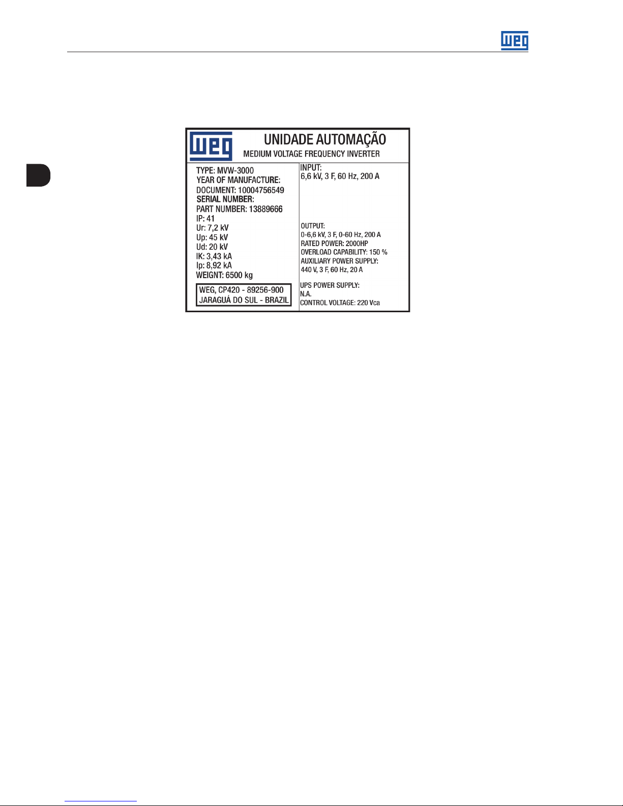
2.2 MVW3000 IDENTIFICATION LABEL
The MVW3000 identification label is positioned in the inner part of the Control Panel of the product. This label
describes important information about the inverter.
Figure 2.1: MVW3000 identification label (example)
2.3 RECEIVING AND STORAGE
The MVW3000 is supplied with the power cells separate from the panel and packed in sets of three cells per
package. The package is composed of OSB frame and injected foam shims. An identification label is affixed to
the outside of the package, identical to the label affixed to the side of the inverter. Compare the content of this
label to the purchase order.
In order to open the cells, see the procedures described in Item 6.1.5 Unpacking on page 6-3. If the MVW3000
cells are not install on the cabinet soon, store them in a clean and dry place (temperature between -25 °C ( -13 °F)
and 50 °C (122 °F) and humidity below 80 %), covered so as protect from dust accumulation and water splashes.
It is recommended to replace the silica gel every three months.
The MVW3000 cabinet has a dehumidifier module, which must remain turned on in case of storage for over thirty
days.
The MVW3000 cabinet is supplied in a cardboard and wood package. The directions for handling, transportation,
mechanical and electrical installations of the product are described in Chapter 6 INSTALLATION, CONNECTION
AND ENERGIZATION on page 6-1, in Item 6.1.5 Unpacking on page 6-3.
MVW3000 | 2-3
2
MVW3000 | 2-3
General Information
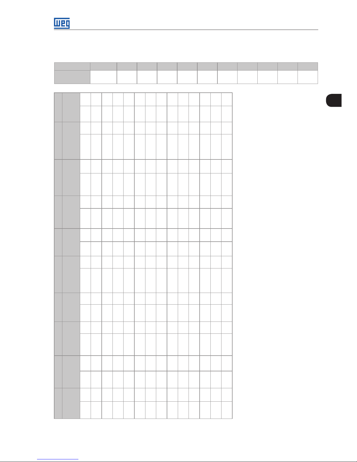
2.4 HOW TO SPECIFY THE MVW3000 MODEL
Table 2.1: MVW3000 Code
Lettering Line 1 2 3 4 5 6 7 8 9 10
Code Example
(¹)
MVW3000 A0140 V063 T5A 066 P A S E R D
1 2 3 4 5 6 7 8 9 10
Rated
Output
Current
Rated
Output
Volt age
Input
Transformer
Input
Rated
Volt age
Manual
Language
Cooling
System
Input
Cubicle
Capacitor
Typ e
Cell
Typ e
Rectifier
Typ e
40 A A0040 2300 V V023 Al - 50 Hz T5A 2300 V 023 English E Air A
Not
included
N Electrolytic E Standard S Diode D
50 A A0050 3300 V V033 Al - 60 Hz T6A 3300 V 033 Spanish S Water W Included S Film F Bypass B AFE A
60 A A0060 4160 V V041 Cu - 50 Hz T5C 416 0 V 0 41 Portuguese P - - - - - - Redundant R - -
70 A A0070 5500 V V055 Cu - 60 Hz T6C 5500 V 055 - - - - - - - - - - - -
80 A A0080 6300 V V063 - - 6000 V 060 - - - - - - - - - - - -
90 A A0090 6900 V V069 - - 6300 V 063 - - - - - - - - - - - -
100 A A0100 7200 V V072 - - 6600 V 066 - - - - - - - - - - - -
110 A A0110 8000 V V080 - - 6900 V 069 - - - - - - - - - - - -
125 A A0125 10000 V V10 0 - - 7200 V 072 - - - - - - - - - - - -
140 A A0140 11000 V V110 - - 8000 V 080 - - - - - - - - - - - -
160 A A0160 1320 0 V V132 - - 10000 V 100 - - - - - - - - - - - -
180 A A0180 138 00 V V138 - - 11000 V 110 - - - - - - - - - - - -
200 A A0200 - - - - 1320 0 V 132 - - - - - - - - - - - -
- - - - - - 1380 0 V 13 8 - - - - - - - - - - - -
(1) For available models, see Table 2.3 on page 2-5 to Table 2.10 on page 2-8.
2-4 | MVW3000
2
General Information
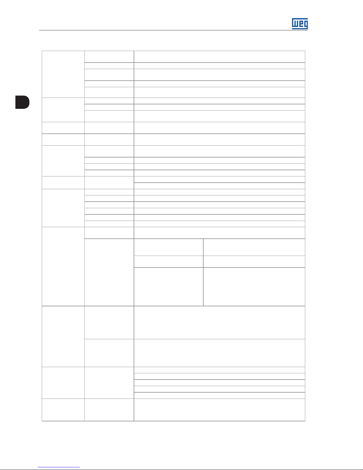
Table 2.2: General specification
POWER SUPPLY
Voltage
2300 V, 3300 V, 4160 V, 5500 V, 6000 V, 6300 V, 6600 V, 6900 V, 7200 V, 8000 V
(± 10 %, -20 % with output power reduction)
Frequency 50 or 60 Hz (specify as necessary) ±3 %
Voltage imbalance
between phases
<3 %
Cos j >0.95
Overvoltage category
Category III
AUXILIARY
SUPPLY
Voltage 220, 380, 400, 415, 440, 460 or 480 V
Frequency 50 or 60 Hz (±3 %)
Voltage imbalance
between phase
<3 %
PROTECTION
DEGREE
Standard
IP41
DIMENSION
Width / Height / Depth
(mm)
16 distinct frames. For all available frames, see Figure 4.3 on page 4-3 and Table 4.2
on page 4-3 to Table 4.8 on page 4-4
ENVIRONMENTAL
CONDITIONS
Temperature
0 to 40 °C (32 °F to 104 °F) (up to 50 °C (122 °F) with 2.5 % reduction in the output
current/ °C)
Humidity 5 to 90 % without condensation
Altitude 0 to 1000 m ( up to 4000 m with derating of 10% / 1000 m )
Pollution degree 2
FINISHING Color
Gray ultra dull (Doors)
Blue ultra dull (Base, Roof, Shutters)
CONTROL
Microprocessor 32 bits
Control method Sinusoidal PWM
Control types Scalar (Imposed Voltage - V/F), Vector (encoder and sensorless)
Switching frequency 500 Hz
Frequency range 0 to 120 Hz
Allowed overload 115 % during 60 seconds, every 10 minutes
PERFORMANCE
Efficiency
Higher 96.5 % (with aluminum transformer)
Higher 97.0 % (with copper transformer)
Speed control
V/F Regulation: 1 % of the nominal speed with slip
compensation
Regulation: 1 rpm (keypad reference)
Sensorless Regulation: 0.5 % of the nominal speed
Speed variation range: 1:100
With Encoder
(using EBA, EBB or EBC board) )
Regulation:
±0.01 % of the nominal speed with a 14-bit analog
input (EBA)
±0.01 % of the nominal speed with digital reference
(keypad, Serial, Fieldbus, Electronic Potentiometer,
Multispeed)
±0.1 % of nominal speed with 10-bit analog input
INPUTS
OUTPUTS
Analogical
2 programmable differential inputs (10 bits ): 0 to 10 V, 0 to 20 mA or 4 to 20 mA
1 programmable bipolar input (14 bits ): -10 V to +10 V, 0 to 20 mA or 4 to 20 mA
1 programmable isolated input (10 bits ): 0 to 10 V, 0 to 20 mA or 4 to 20 mA
2 programmable outputs (11 bits ): 0 to 10 V
2 bipolar programmable outputs (14 bits ): (-10 to +10) V
2 programmable isolated outputs (11 bits): 0 to 20 mA or 4 to 20 mA
Digital Analog
Relay Transistor
8 programmable isolated inputs: 24 Vdc
1 programmable isolated input: 24 Vdc
1 programmable isolated input: 24 Vdc (for motor PTC thermistor)
5 programmable outputs, contacts NO/NC: 240 Vac, 1 A
2 programmable isolated open collector outputs: 24 Vdc, 50 mA
COMMUNICATION
Serial Interface
Fieldbus Networks
RS-232 (point to point)
RS-485, isolated, via EBA or EBB board (multipoint up to 30 inverters)
Modbus RTU (incorporated software) via RS-485 serial interface
Profibus DP or DeviceNet via additional kits
Ethernet and Profinet
SAFETY
Protections (memory
of the last 100 faults/
alarms with date and
time)
See fault in the programming manual available for download on: www.weg. net
MVW3000 | 2-5
2
MVW3000 | 2-5
General Information
APPLICABLE
STA NDA RDS
Electromagnetic
compatibility
EMC directive 89 / 336 / EEC - industrial environment
EN 61800-3 Standard (EMC - Emission and Immunity)
CEI - IEC 61800
Adjustable Speed Electrical Power Drive System
Part 4 - General Requirements
Part 5 - Safety Requirements
HUMAN MACHINE
INTERFACE
(LCD DISPLAY)
Command
Start/Stop, Parameterization (Programming of general functions)
Increase/decrease the speed
JOG, Forward/Reverse selection, Local/Remote selection
Supervision (Reading)
Speed reference (rpm)
Motor speed (rpm)
Value proportional to the speed (e.g.: m/min)
Motor output frequency (Hz)
Voltage on the intermediate circuits (V)
Motor torque (%)
Output power (kW)
Energized time (h)
Operation time (h)
Motor current (A)
Motor voltage (V)
Inverter status
Digital input status
Digital output (transistor) status
Relay output status
Analog input values
100 last erros in the memory with date and time
Fault/alarm messages
AVAILABLE
RESOURCES/
FUNCTIONS
Options
Fieldbus network communication kits (installation inside the inverter)
SUPERDRIVE kit with RS-232 serial communication interface (Inverter - PC)
Kit Ethernet
Kit Expansão de I/Os Profibus DP
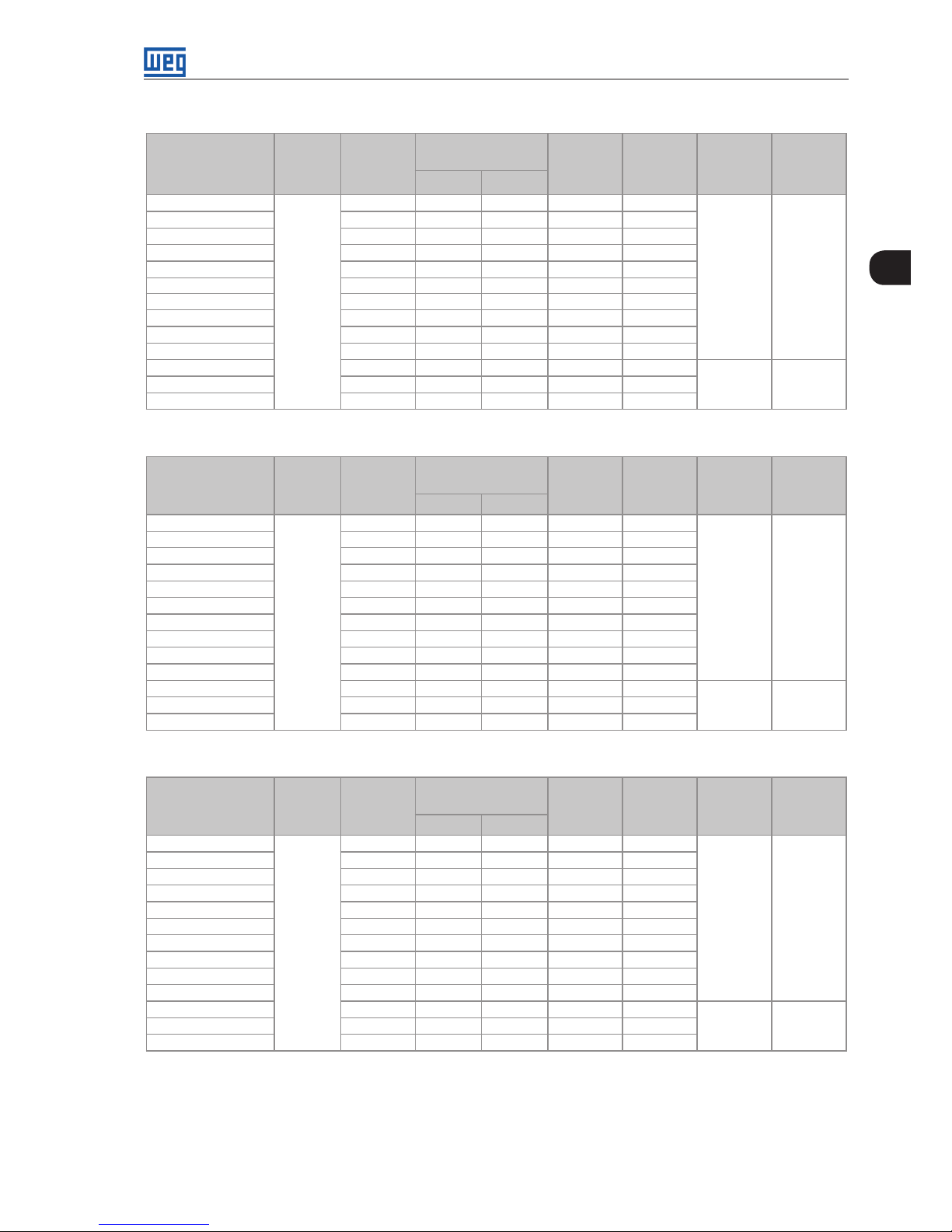
2.4.1 Available Models
The MVW3000 line of medium voltage inverters offers different models, classified according to their rated voltage
and current levels. Different models of the MVW3000 may have distinct frames, which are presented in Table 2.3
on page 2-5 with their respective codes. For the constructive aspects of the available frames, see Chapter 4
TECHNICAL DATA on page 4-1, Figure 4.3 on page 4-3 and Table 4.2 on page 4-3 to Table 4.8 on page
4-4. For models with rated voltage above 8000 V, contact WEG.
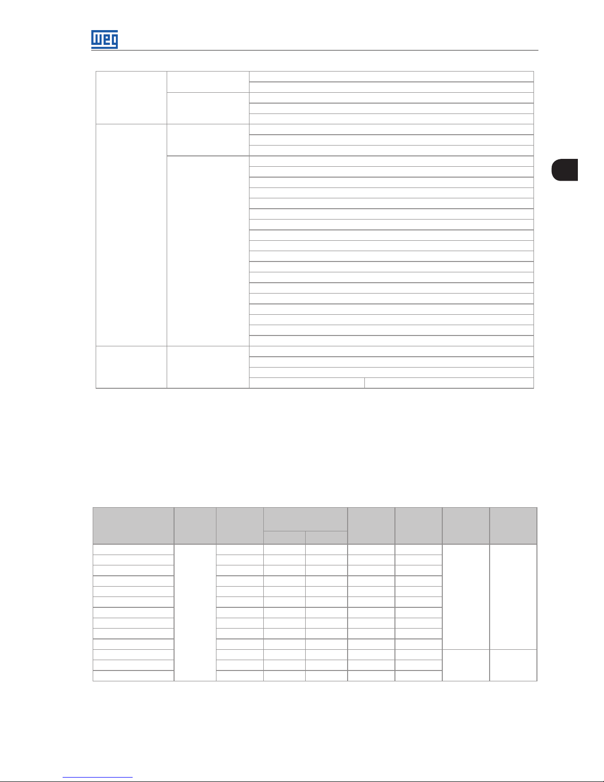
Table 2.3: MVW3000 2300 V models
Models
Nominal
Volt age [V]
Rated
Current
[A]
Motor Rated Power
(1)
Dissipated
Power
(2)
[kW]
Dissipated
Power
(3)
[kW]
Flow
Frame
Size
[HP] [kW]
MVW3000 A0040 V023
2300
40 170 130 5.03 4.29
7062 CFM or
12000 m³/h
B2
MVW3000 A0050 V023 50 220 165 6.29 5.36
MVW3000 A0060 V023 60 265 200 7.54 6.43
MVW3000 A0070 V023 70 315 235 8.80 7.5 0
MVW3000 A0080 V023 80 355 265 10.06 8.58
MVW3000 A0090 V023 90 400 300 11.31 9.65
MVW3000 A0100 V023 100 445 335 12.57 10.72
MVW3000 A0110 V023 110 485 365 13.83 11.79
MVW3000 A0125 V023 125 560 420 15.71 13.40
MVW3000 A0140 V023 140 630 470 17.6 0 15.01
MVW3000 A0160 V023 160 715 535 20.11 17.15
8828 CFM or
15000 m³/h
C2MVW3000 A0180 V023 180 810 605 22.63 19.29
MVW3000 A0200 V023 200 895 670 25.14 21.44
2-6 | MVW3000
2
General Information
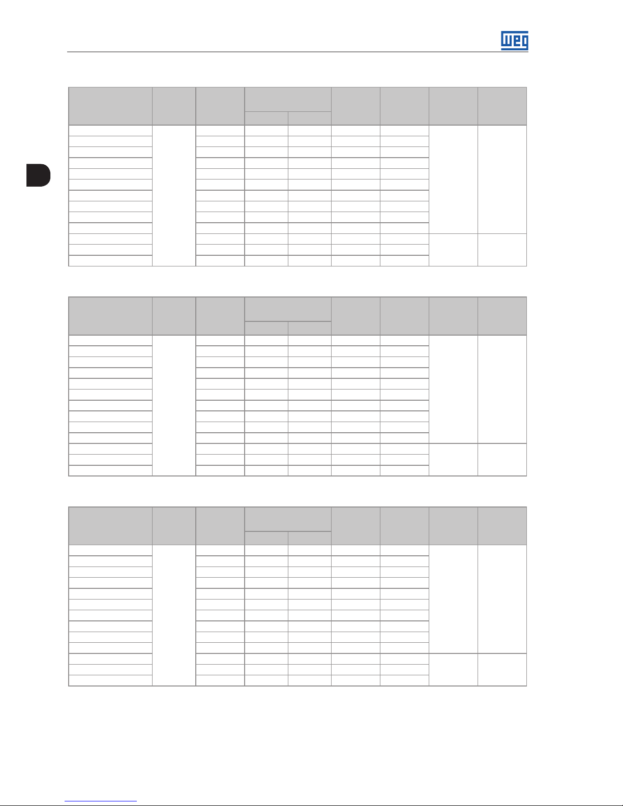
Table 2.4: MVW3000 3300 V models
Models
Nominal
Volt age
[V]
Rated
Current
[A]
Motor Rated Power
(1)
Dissipated
Power
(2)
[kW]
Dissipated
Power
(3)
[kW]
Flow
Frame
Size
[HP] [kW]
MVW3000 A0040 V033
3300
40 250 190 7.2 1 6 .15
7062 CFM or
12000 m³/h
B3
MVW3000 A0050 V033 50 320 240 9.02 7.6 9
MVW3000 A0060 V033 60 380 285 10.82 9.23
MVW3000 A0070 V033 70 445 335 12.63 10.77
MVW3000 A0080 V033 80 515 385 14.43 12. 30
MVW3000 A0090 V033 90 575 430 16.23 13.84
MVW3000 A0100 V033 100 640 480 18.04 15.3 8
MVW3000 A0110 V033 110 710 530 19.84 16.92
MVW3000 A0125 V033 125 800 600 22.54 19.22
MVW3000 A0140 V033 14 0 900 675 25.25 21.53
MVW3000 A0160 V033 160 1030 770 28.86 24.61
8828 CFM or
15000 m³/h
C3
MVW3000 A0180 V033 18 0 1155 865 32.46 2 7. 6 8
MVW3000 A0200 V033 200 1285 960 36.07 30.76
Table 2.5: MVW3000 4160 V models
Models
Nominal
Volt age
[V]
Rated
Current
[A]
Motor Rated Power
(1)
Dissipated
Power
(2)
[kW]
Dissipated
Power
(3)
[kW]
Flow
Frame
Size
[HP] [kW]
MVW3000 A0040 V041
4160
40 320 240 9.09 7.76
77062 CFM
or
12000 m³/h
B4
MVW3000 A0050 V041 50 400 300 11.37 9.69
MVW3000 A0060 V041 60 480 360 13.64 11.63
MVW3000 A0070 V041 70 565 425 15.92 13.57
MVW3000 A0080 V041 80 650 485 18.19 15.51
MVW3000 A0090 V041 90 730 545 20.46 17. 4 5
MVW3000 A0100 V041 100 810 605 2 2.74 19.39
MVW3000 A0110 V041 110 890 665 25.01 21.33
MVW3000 A0125 V041 125 1015 760 28.42 24.23
MV W30 0 0 A0140 V041 140 1135 850 31. 83 2 7.14
MVW3000 A0160 V041 160 1300 970 36.38 31.02
8828 CFM or
15000 m³/h
C4
MVW3000 A0180 V041 180 1460 1090 40.92 34.90
MVW3000 A0200 V041 200 1625 1215 4 5.47 38.78
Table 2.6: MVW3000 5500 V models
Modelos
Nominal
Volt age
[V]
Rated
Current
[A]
Motor Rated Power
(1)
Dissipated
Power
(2)
[kW]
Dissipated
Power
(3)
[kW]
Flow
Frame
Size
[HP] [kW]
MVW3000 A0040 V055
5500
40 425 320 12.02 10.25
7062 CFM or
12000 m³/h
B5
MVW3000 A0050 V055 50 535 400 15.03 12.82
MVW3000 A0060 V055 60 640 480 18.04 15.38
MVW3000 A0070 V055 70 750 560 21.0 4 17. 9 4
MVW3000 A0080 V055 80 855 640 24.05 20.51
MVW3000 A0090 V055 90 965 720 2 7. 0 5 23.07
MVW3000 A0100 V055 100 1070 800 30.06 25.63
MVW3000 A0110 V055 110 1175 880 33.07 28.20
MVW3000 A0125 V055 125 1340 1000 37. 5 7 32.04
MVW3000 A0140 V055 14 0 1505 1125 42.08 35.89
MVW3000 A0160 V055 160 1720 1285 4 8 .10 41.01
8828 CFM or
15000 m³/h
C5
MVW3000 A0180 V055 180 1935 1445 5 4.11 4 6 .14
MVW3000 A0200 V055 200 2150 1605 6 0 .12 51.27
MVW3000 | 2-7
2
MVW3000 | 2-7
General Information
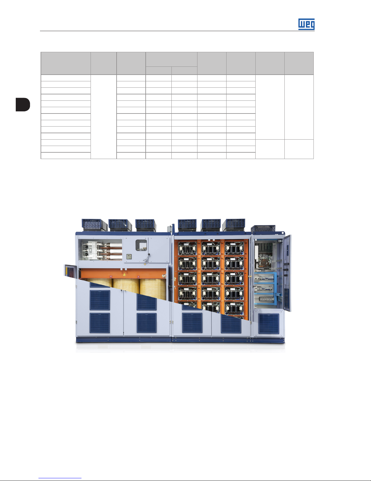
Table 2.7: MVW3000 6300 V models
Models
Nominal
Volt age
[V]
Rated
Current
[A]
Motor Rated Power
(1)
Dissipated
Power
(2)
[kW]
Dissipated
Power
(3)
[kW]
Flow
Frame
Size
[HP] [kW]
MVW3000 A0040 V063
6300
40 485 485 13.77 11.74
7062 CFM or
12000 m³/h
B6
MVW3000 A0050 V063 50 615 615 17. 2 2 14.68
MVW3000 A0060 V063 60 735 735 20.66 17. 6 2
MVW3000 A0070 V063 70 855 855 24 .10 20.55
MVW3000 A0080 V063 80 985 985 2 7. 5 5 23.49
MVW3000 A0090 V063 90 1105 110 5 30.99 26.42
MVW3000 A0100 V063 100 1230 1230 34.43 29.36
MVW3000 A0110 V063 110 1350 1350 3 7. 8 8 32.30
MVW3000 A0125 V063 125 1540 1540 43.04 36.70
MVW3000 A0140 V063 14 0 1720 172 0 48.20 41.11
MVW3000 A0160 V063 16 0 1970 1970 55.09 46.98
8828 CFM or
15000 m³/h
C6
MVW3000 A0180 V063 18 0 2215 2215 61. 98 52.85
MVW3000 A0200 V063 200 2465 2465 68.86 58.72
Table 2.8: MVW3000 6900 V models
Models
Nominal
Volt age
[V]
Rated
Current
[A]
Motor Rated Power
(1)
Dissipated
Power
(2)
[kW]
Dissipated
Power
(3)
[kW]
Flow
Frame
Size
[HP] [kW]
MVW3000 A0040 V069
6900
40 535 400 15.08 12.86
7062 CFM or
12000 m³/h
B6
MVW3000 A0050 V069 50 670 500 18.86 16.08
MVW3000 A0060 V069 60 810 605 22.63 19.29
MVW3000 A0070 V069 70 945 705 26.40 22.51
MVW3000 A0080 V069 80 1075 805 3 0.17 25.73
MVW3000 A0090 V069 90 1210 905 33.94 28.94
MVW3000 A0100 V069 100 1345 1005 3 7. 71 32.16
MVW3000 A0110 V069 110 1480 110 5 41.4 8 35.37
MVW3000 A0125 V069 125 1685 1260 4 7.14 40.20
MVW3000 A0140 V069 14 0 1890 1410 52.80 45.02
MVW3000 A0160 V069 16 0 2155 1610 60.34 51.4 5
8828 CFM or
15000 m³/h
C6
MVW3000 A0180 V069 18 0 2430 1815 67.8 8 5 7. 88
MVW3000 A0200 V069 200 2700 2015 75.42 64.31
Table 2.9: MVW3000 7200 V models
Models
Nominal
Volt age
[V]
Rated
Current
[A]
Motor Rated Power
(1)
Dissipated
Power
(2)
[kW]
Dissipated
Power
(3)
[kW]
Flow
Frame
Size
[HP] [kW]
MVW3000 A0040 V072
7200
40 560 420 15.74 13.42
10595 CFM or
18000 m³/h
B7
MVW3000 A0050 V072 50 700 525 19.68 16.78
MVW3000 A0060 V072 60 840 630 23.61 20.13
MVW3000 A0070 V072 70 985 735 27.5 5 23.49
MVW3000 A0080 V072 80 1125 840 31.48 26.84
MVW3000 A0090 V072 90 1265 945 35.42 30.20
MVW3000 A0100 V072 100 1405 1050 39.35 33.56
MVW3000 A0110 V072 110 1545 1155 43.29 36.91
MVW3000 A0125 V072 125 176 0 1315 49.19 41.94
MVW3000 A0140 V072 140 1970 1470 55.09 46.98
MVW3000 A0160 V072 160 2250 1680 62.96 53.69
13243 CFM or
22500 m³/h
C7
MVW3000 A0180 V072 180 2530 189 0 70.83 60.40
MVW3000 A0200 V072 200 2815 2100 78.70 6 7.11
2-8 | MVW3000
2
General Information
Table 2.10: MVW3000 8000 V models
Models
Nominal
Volt age
[V]
Rated
Current
[A]
Motor Rated Power
(1)
Dissipated
Power
(2)
[kW]
Dissipated
Power
(3)
[kW]
Flow
Frame
Size
[HP] [kW]
MVW3000 A0040 V080
8000
40 620 465 17.49 14.91
10595 CFM or
18000 m³/h
B8
MVW3000 A0050 V080 50 775 580 21.8 6 18.64
MVW3000 A0060 V080 60 935 700 26.23 22.37
MVW3000 A0070 V080 70 1090 815 30.61 2 6 .10
MVW3000 A0080 V080 80 1250 935 34.98 29.83
MVW3000 A0090 V080 90 14 0 5 1050 39.35 33.56
MVW3000 A0100 V080 100 1560 116 5 43.72 37.28
MVW3000 A0110 V080 110 1720 1285 4 8 .10 41.01
MVW3000 A0125 V080 125 1955 1460 54.65 46.60
MVW3000 A0140 V080 140 2190 1635 61. 21 52.20
MVW3000 A0160 V080 160 2505 1870 69.96 59.65
13243 CFM or
22500 m³/h
C8
MVW3000 A0180 V080 180 2815 2100 78.70 67.11
MVW3000 A0200 V080 200 3130 2335 87.45 74.57
(1) The motor powers are only illustrative, and the correct inverter selection must be done as a function of the rated current of the motor to be used, as well
as the overloads related to the application. The motor rated output takes into account the operation with power factor 0.87 and 97 % of efficiency at full load.
(2) Dissipated power considering transformer with aluminum winding and operation under the conditions of Note (1).
(3) Dissipated power considering transformer with copper winding and operation under the conditions of Note (1).
Notes:
1 hp = 0.746 kW
1kW = 3412.14 BTU/hour for the dissipated power.
1 m³/h = 0.5885 CFM
Figure 2.2: MVW3000 panel general view (Frame size B6)
MVW3000 | 3-1
3
MVW3000 | 3-1
Product Characteristics
3 PRODUCT CHARACTERISTICS
A brief theoretical explanation about the operation and a simplified electrical scheme of the power cells and
their connections are presented below. The basic operation of the control system is presented at the end of this
chapte r.
The MVW3000 is a frequency inverter designed to control medium voltage motors at the rated values of 2.3 kV to
13.8 kV and for a power range of 150 HP to 5400 HP. Based on a topology where the low voltage cells (< 1000
V) are connected in series to form each inverter phase, its assembly is modular, enabling different configurations
if necessary to drive high power motors.
NOTE!
The characteristics contained in this manual were based on models of the standard MVW3000
intended for applications on 6.6 kV motors. Therefore, the MVW3000 used in the general illustrations
will contain 18 low voltage power cells (six in series per phase). Notice that the MVW3000 can be
engineered to meet the needs and technical specifications of our customers. Contact out technical
team for more details.
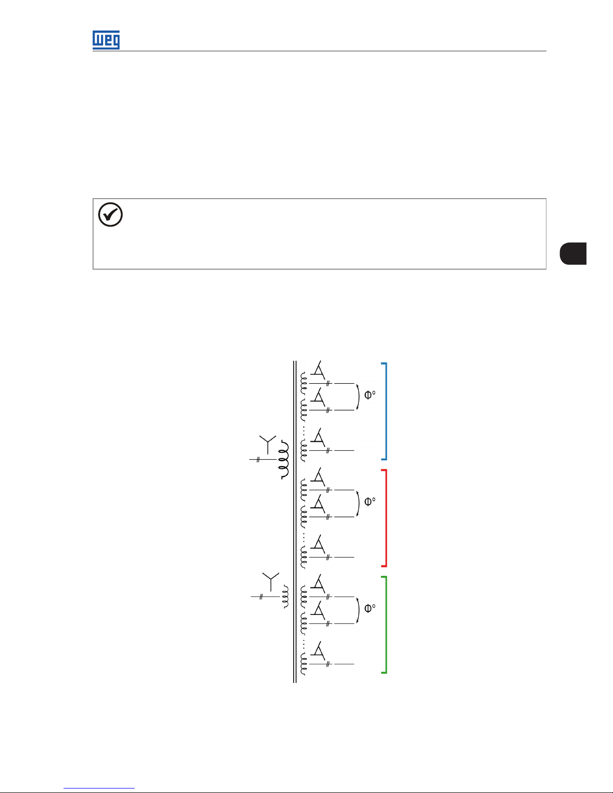
3.1 INPUT TRANSFORMER
The MVW3000 inverter has an input transformer, because the cascade cell topology demands the feeding of
each cell to be insulated from each other. This transformer is built so as to meet the different functions for the
MVW3000, such as the necessary insulation for the power cells, cancellation of the harmonic current coming
from the cell input rectifiers, and it also has an auxiliary winding responsible for the system pre-charge.
V phase cells
Medium voltage
input
Auxiliary input
(pre-charge)
W phase cells
U phase cells
U1
U2
Un
V1
V2
Vn
W1
W2
Wn
Figure 3.1: Input phase-shifting transformer diagram
3-2 | MVW3000
3
Product Characteristics
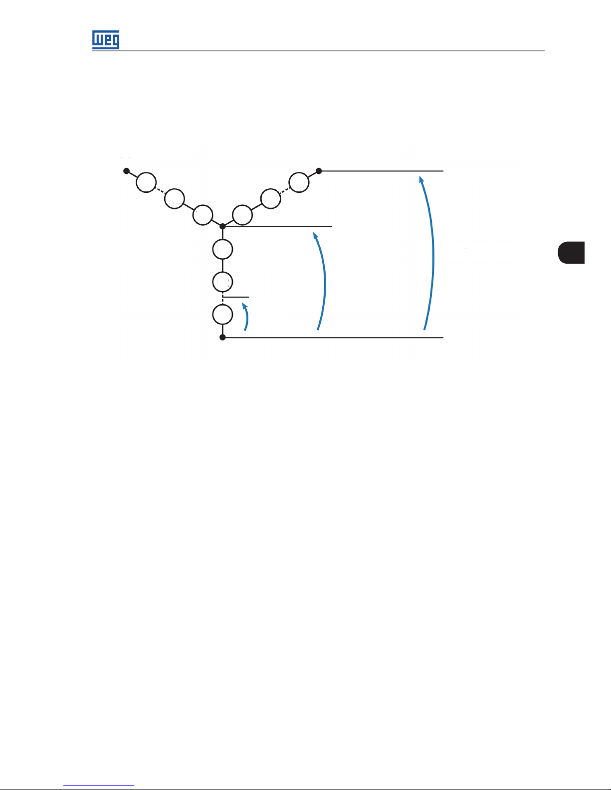
The transformer configuration is made in star – extended delta, with phase-shifting angles j° between the
secondary windings of one same phase. The main primary windings (star connection) and the auxiliary input
windings (also star) do not present phase shifting between each other.
The transformer is designed according to the number of cells used on the inverter. 3x3xn windings (number of
motor phases x number of cell input phases x number of cells per phase) form n isolated secondary windings that
process 1/(3n) of the converter rated power, totalizing one secondary winding per cell.
Motor Voltage [kV] 2.3 3.3 4 .16 5.5 6-69 7. 2 8
Secondary Windings 3x2=6 3x3=9 3x4=12 3x 5 =15 3x 6 =18 3x7= 21 3x8=24
The transformer secondary windings have phase-shifting designed according to the number of cells and the
specified harmonic level, and it may be engineered upon the customer’s request The phase-shifting help cancel
the harmonic components coming from the non-controlled semiconductors devices. As each cell has a 6-pulse
diode rectifier at the input, and the secondary windings have a phase-shifting between each other, the transformer
primary winding perceives multiples of six pulses in its windings.
The bigger the number of pulses, the smaller the phase-shifting angle between the secondary windings, and
the smaller the Harmonic distortion rate observed by the transformer primary winding. Smaller phase-shifting
angles imply more complex manufacture and parameter control of the transformer. Thus, a good complexityperformance ratio is sought.
For the 18-cell MVW3000, the 36-pulse transformer Figure 3.2 on page 3-3 is used, which offers good
cost effectiveness with great performance regarding harmonic component cancellation and reduced cost, in
comparison to transformers with more pulses.
Table 3.1 on page 3-2 contains the possible input transformer configurations for different numbers of cells
installed on the MVW3000 panel.
Table 3.1: Possible number of pulses to obtain in relation to the number of cells
Cells per Phase Total Cells Number of Pulses
2 6 36, 18
(1)
, 12, 6
3 9 54, 18
(1)
, 6
4 12 72, 36, 24
(1)
, 18, 12, 6
5 15 90, 30
(1)
, 18, 6
6 18 108, 54, 36
(1)
, 18, 12, 6
7 21 12 6, 126, 42
(1)
, 18, 6
8 24 144, 72, 48, 36
(1)
, 24, 18, 12, 6
(1) Stand ard op tion.
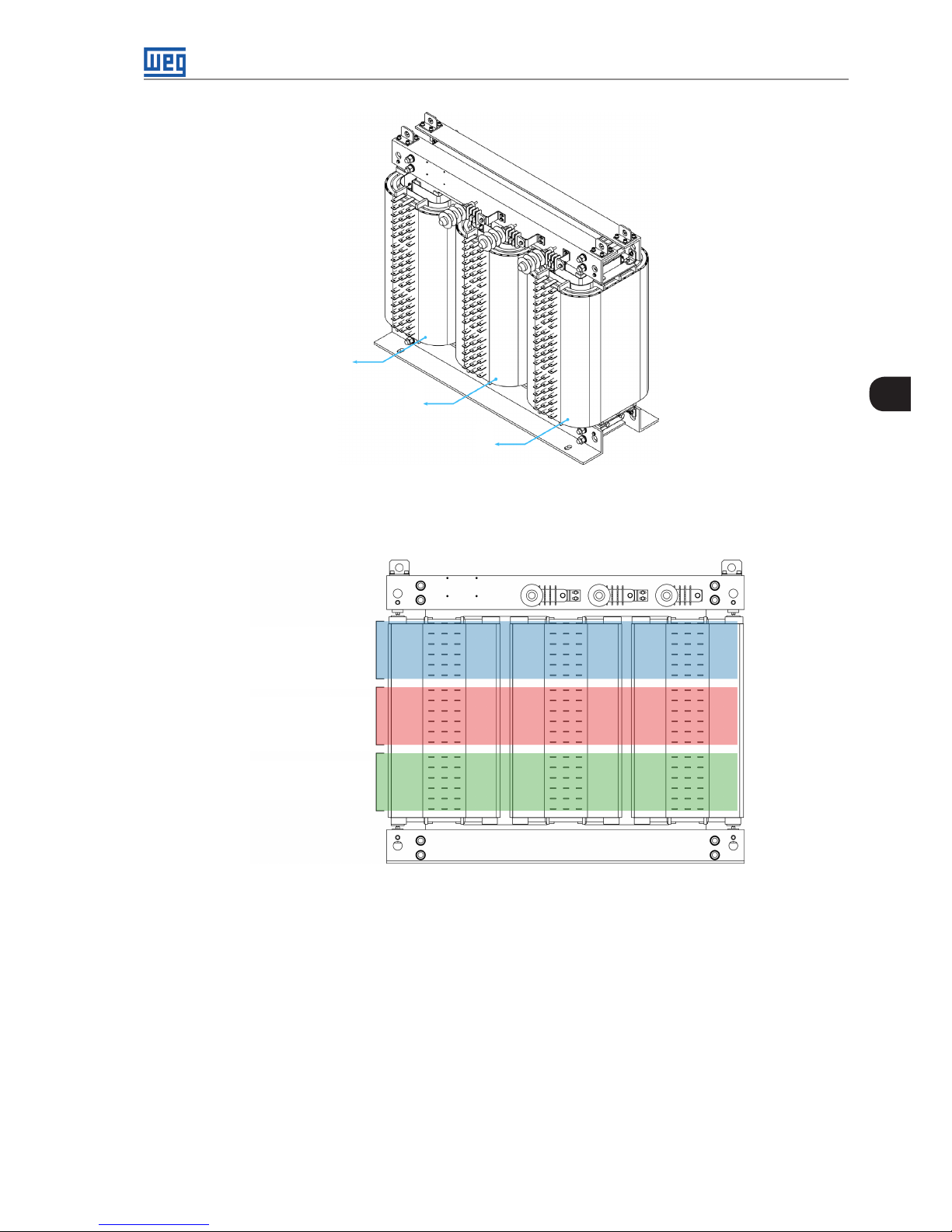
Figure 3.2 on page 3-3 indicates the connection points for the power cell inputs, in this case, the phases R, S
and T. The windings with 690 V
rms
of rated voltage process 1/18 of the converter rated power, in the case of the
18-cell MVW3000.
MVW3000 | 3-3
3
MVW3000 | 3-3
Product Characteristics
R
S
T
Figure 3.2: Input transformer of the 18-cell MVW3000 (Frame B6)
Physically, the cells that form phases U, V and W are connected to the main transformer according to Figure 3.3
on page 3-3.
U phase cells
V phase cells
W phase cells
Figure 3.3: Cell connection area of each phase
The transformer has its own panel, being thus totally integrated to the MVW3000. For more details on the panels,
refer to Chapter 4 TECHNICAL DATA on page 4-1, Figure 4.3 on page 4-3, Table 4.2 on page 4-3 to Tabl e
4.8 on page 4-4.
3.2 POWER CELLS
The power cells used on the arms of the MVW3000 are single-phase low voltage inverters (output voltage of
690 V
rms
), in a topology known as H bridge or full bridge. A basic diagram of the rms power cell circuit can be seen
in Figure 3.4 on page 3-4. Each cell has the feeding of one own secondary winding (three-phase) of the main
transformer, which ensures the converter medium voltage insulation.
The three-phase voltages of the input of the modules are then rectified by a Graetz bridge using non-controlled
semiconductor devices (diodes), forming one own DC link (direct current) with the addition of the capacitors to
the cell (represented by symbol C1). They can be electrolytic or plastic film capacitors, depending on the model
of the used cell.

3-4 | MVW3000
3
Product Characteristics
R
S
T
F1
F2
D1
D3 D5
D2 D4
D6
R1
R2
C1
Gate driver
Bypass
Gate driver
FA
NE
Measurement
Supply
Fiber optic
Local control
R
T
S
N
P
FA
NE
24 V
15 V
5 V
GND
NTC1
GND
S1n, S2n
15 v
XC3
15 v
GND
NTC2
S1f, S2f
Tx
Rx
Figure 3.4: Basic diagram of a power cell
IGBT (Insulated Bipolar Gate Transistor) controlled semiconductor devices are used to implant the inverter bridge
in H; thus, each power cell has four IGBTs in the configuration shown above. During operation, the voltage
between FA and NE output terminals has three possible voltage levels. Considering that the DC link voltage of
each cell is VDC and that only two IGBTs can be operating simultaneously (due to short circuit protection), when
S1f and S2n are operating, the voltage between FA and NE will be + VDC, whereas if S1n and S2f start operating,
the voltage between FA and NE will be –VDC. If S1n and S1f or S2n and S2f are turned on, the voltage, in both
cases, will be equal the zero.
To protect the modules, two fuses F1 and F2 are connected to the input phases R and T, as shown in Figure 3.1
on page 3-1. In case a module presents some fault, the bypass system, when available, will be responsible for
circumventing the fault, removing it from the series and enabling the operation to continue.
When that occurs, control strategies will be applied so that the load remains operating. Further information can
be found in Chapter 8 SPECIAL FUNCTIONS on page 8-1, in Section 8.3 CELL BYPASS on page 8-5.
Each power cell has one local control module. This module communicates with the main control module by
means of an optical-fiber interface, necessary to obtain, in addition to the insulation degree required for the
communication, noise immunity, greater robustness and reliability, characteristics necessary for the application.
The local control makes acquisitions and monitors relevant magnitudes for the cell operation.
Some of the monitored magnitudes are the line voltages of the power cell, temperature of the diode modules and
IGBTs, voltage of the DC link capacitors, voltage of the cell power supplies, among others.
The local control is also responsible for local activations, such as the switching of the IGBTs and the trigger of
the bypass system. In case the cell presents readings out of the expected operation standards, for example,
temperatures close to damaging the semiconductors, overvoltage on the DC link, or other faults predicted by
the control, the bypass system may be activated for protection against a possible cell failure or for removing an
already damaged cell from operation.
MVW3000 | 3-5
3
MVW3000 | 3-5
Product Characteristics
3.3 CONNECTION OF THE CELLS
To form a three-phase output, a number “n” of power cells that operate with 690 “V
rms
” of output are rms grouped
in series per phase. The cell sets that represent phases U, V and W are connected in star configuration, with a
floating neutral in common with the phases, as indicated in Figure 3.5 on page 3-5.
n x 690 V
690 V
V
W
U
√3 x n x 690 V
Vn
V2
V1W1
W2
Wn
U1
U2
Un
Figure 3.5: Cell-to-phase connection diagram
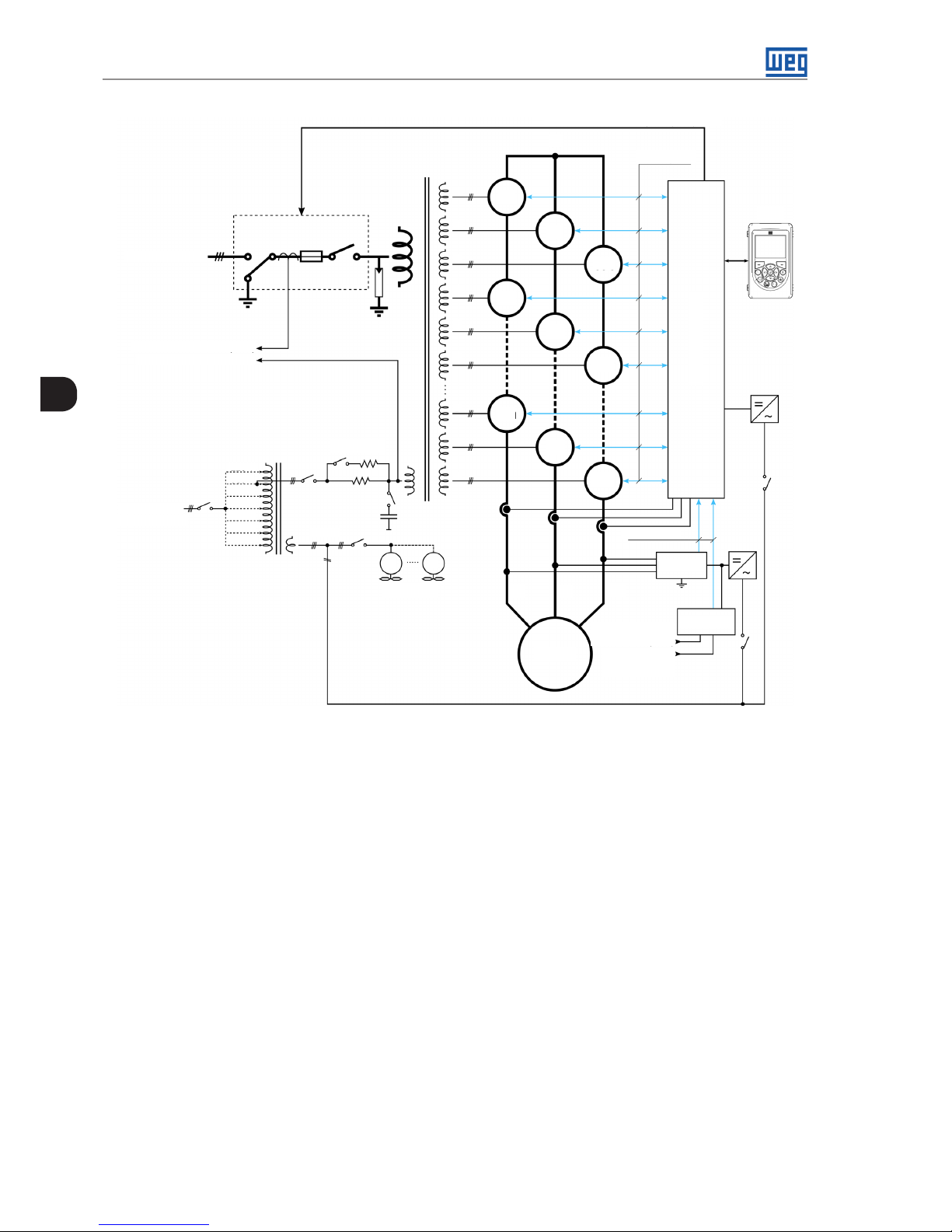
Figure 3.6 on page 3-6 shows the transformer, input switchgear and secondary winding connected to each
cell. This association in series enables more voltage levels at the inverter output. Locally, each cell produces three
voltage levels; however, at the converter three-phase output, it is possible to obtain 2n + 1 levels on the phase
voltage and 4n+1 levels on the line voltage.
This effect occurs, because the voltage of each phase is instantaneously given by the addition of the voltages at
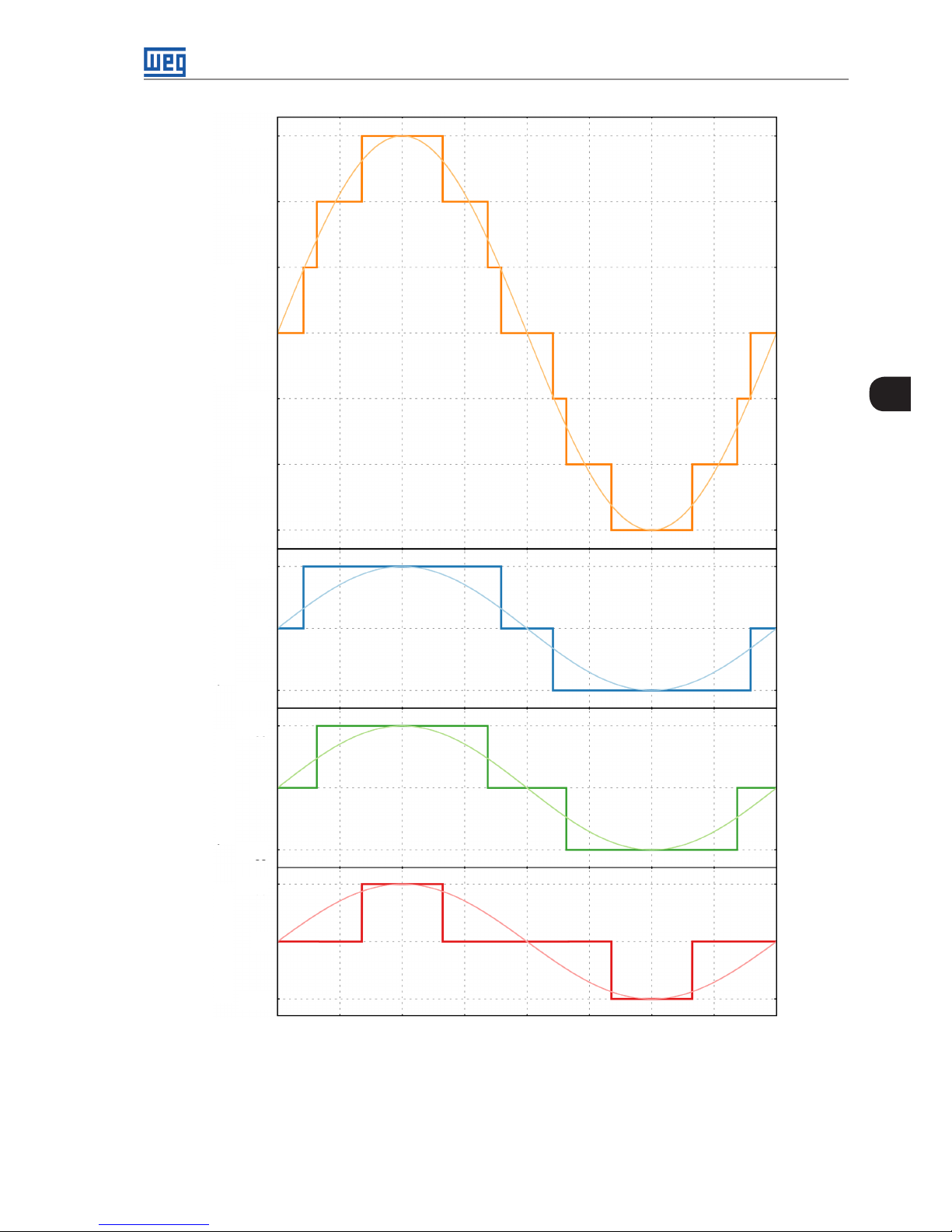
terminals FA and NE of each cell pertaining to the analyzed phase. Figure 3.7 on page 3-7 shows the sum of
the voltages of each cell to form the phase voltage in a 9-cell MVW3000 (3 per phase).
3-6 | MVW3000
3
Product Characteristics
Input MT 3~
Currents (S andT)
Voltages (R, S and T)
Line BT 3~
220 V...480 V
220 V
380 V
400 V
415 V
440 V
440 V
440 V
Pre-load
Ventilation
220 V
M
M
zº
yº
zº
zº
yº
yº
xº
xº
xº
Fiber optic
Input switchgear command
HMI
N
U1
V1
W1
U2
V2
W2
Un
Vn
Wn
Fiber optic
Currents
(S and T)
Voltages
(R, S and T)
ISOC.22
ISOC2.00
Main control
Motor
U
V
W
Figure 3.6: MVW3000 simplified diagram for n power cells
Therefore, increasing the number of cells per phase, in addition to enabling the drive of motors with higher
voltages and powers, a better sinusoidal shaped wave is obtained. Thus, the converter provides a smaller THD
(total harmonic distortion), reduction of noises and vibration on the motor, operating with high efficiency.
MVW3000 | 3-7
3
MVW3000 | 3-7
Product Characteristics
Voltage on phase U
+3 V
CC
Voltage on cell U1Voltage on cell U2
Voltage on cell U3
+2 V
CC
+V
CC
-V
CC
0
-2 V
CC
-3 V
CC
+V
CC
0
-V
CC
+V
CC
0
-V
CC
+V
CC
0
-V
CC
Figure 3.7: Wave form of the phase voltage for a CHB of 3 cells per phase
The diagram also shows the medium voltage input switchgear, the low voltage auxiliary winding to perform the
pre-charge of the cell capacitors, as well as the fiber optic interface between the main control and the local
control of the power cells.
3-8 | MVW3000
3
Product Characteristics
3.4 CONTROL
The MVW3000 has protections against overload, short circuit, current limit, under and overvoltage,
overtemperature, ground fault and monitoring of the individual faults of each power cell. The control type can be
selected by the user between: scalar control (constant V/f ratio) or vector control (sensorless or with feedback by
speed sensor).
The MVW3000 inverter uses the PWM modulation technique (Pulse Width Modulation); from the direct voltage
of each independent DC links, it synthesizes an alternate voltage with variable frequency and amplitude at the
output terminals. The medium voltage level is obtained at the converter output terminals from the association of
“n” low voltage cells in series. For further information on the central control, refer to Section 4.3 CONTROL RACK
on page 4-6.
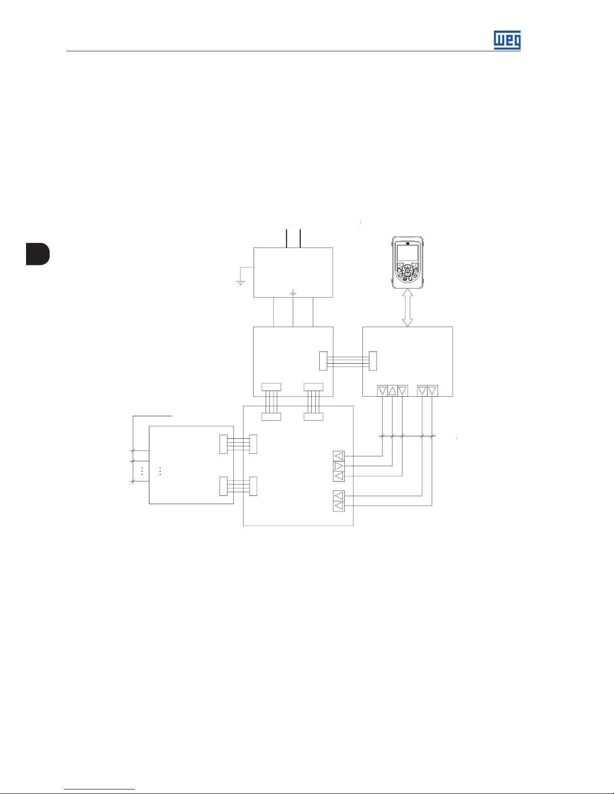
HMI
MVC4PIC
PS24
24 V 0 V
MVC3
F.O .
F.O .
U1
U2
Wn
FOI3.02
Input BT (220 V 1~ or 3~)
Figure 3.8: Central control simplified diagram
The output currents of the three phases (motor currents) are measured using the Hall-effect CTs (current
transformers). Those current signals are sent to the central control board. The measurement is done for indication
on the HMI and for implanting the converter control and protection functions.
The pre-charge is done by means of an auxiliary winding of the input transformer, which is driven by the inverter
auxiliary supply circuit via current limiter elements. In order to prevent high starting current levels on the inverter,
activation of protection systems or even damages to its own components, the cell capacitor pre-charge must be
done through and auxiliary winding of the input transformer. The auxiliary supply is also responsible for feeding
the control circuit and fans for the panel cooling.
MVW3000 | 4-1
4
MVW3000 | 4-1
Technical Data
4 TECHNICAL DATA
This chapter contains technical information on the MVW3000, cabinet details, input transformer, power cell and
control rack. It also provides information about the available output filters for the MVW3000.
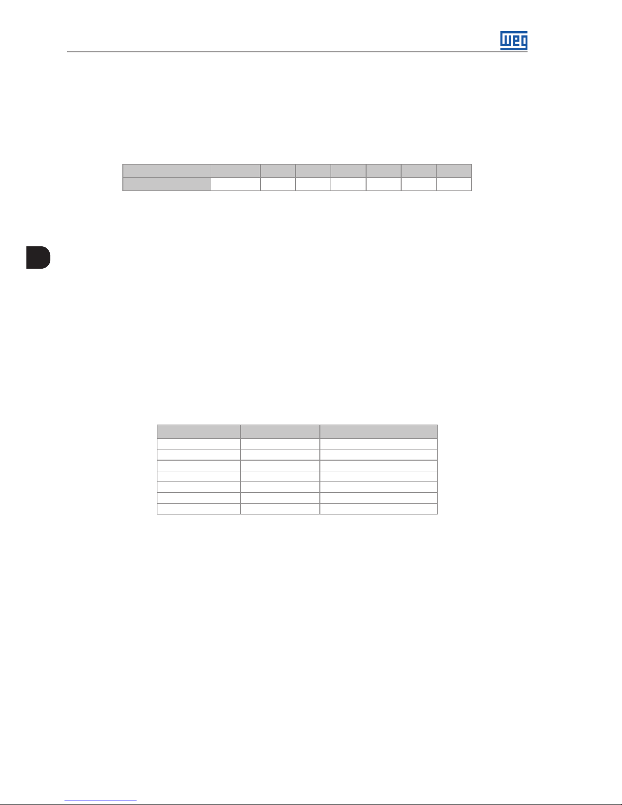
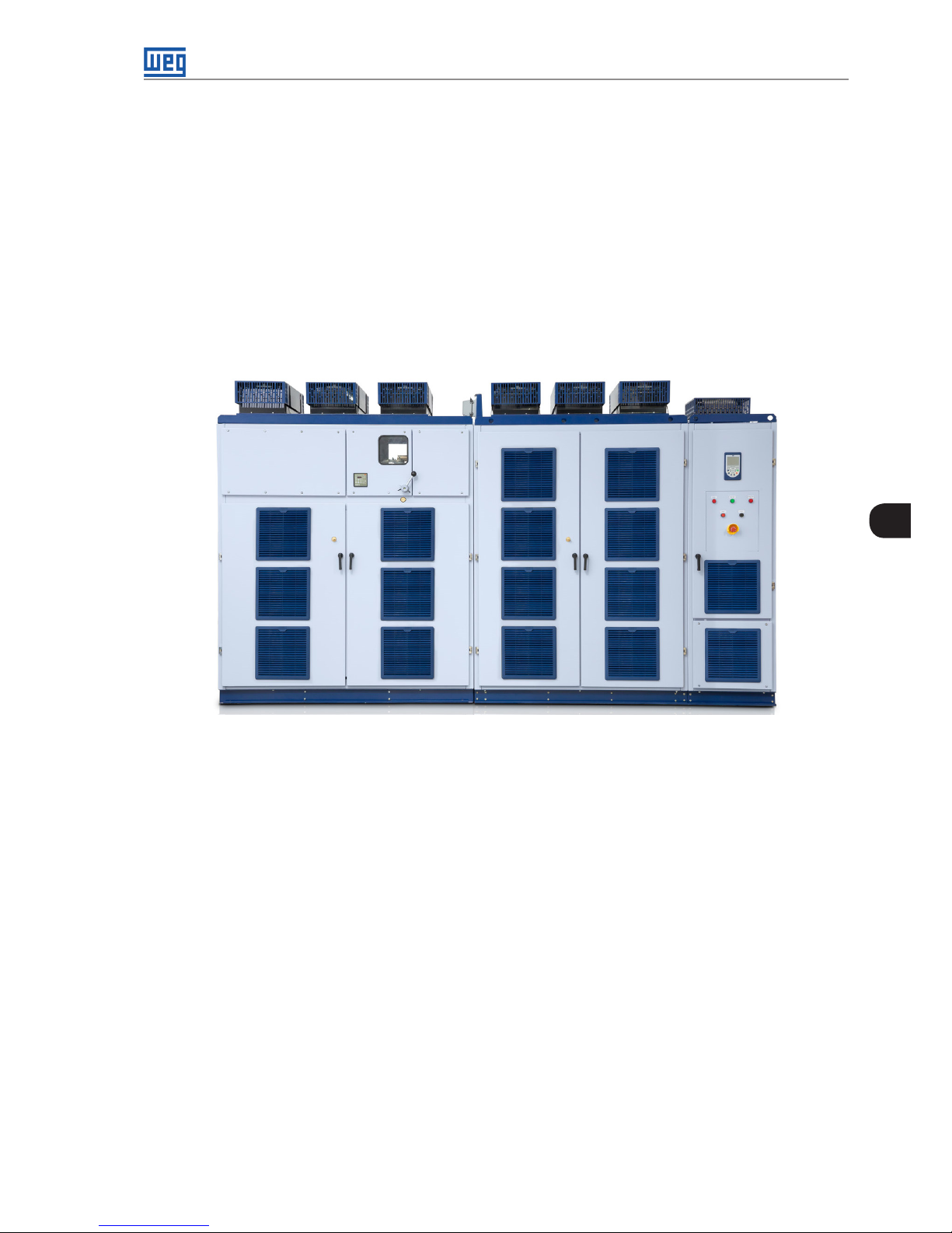
4.1 MVW3000 PANEL
The MVW3000 is assembled as coupled panels forming four distinct compartments. In the first column of the
panel, to the left, are the input safety devices, such as fuses and the input circuit breaker/contactor (if installed).
This part also shows the input transformer temperature on the temperature display. Below the safety devices, in
a separate section, is the main medium voltage input transformer. In the central section, the inverter power cells
are installed; each of the three columns shown in Figure 4.2 on page 4-2 represents each of the three inverter
phases: U, V and W.
Transformer and Circuit
Inverter
Control
Figure 4.1: Closed panel of the 18-cell MVW3000 (Frame B6)
The handles of average tension that feed the cells of the invertor come from the secondary ones of the transforming
one of entrance. The number of cables and conductor diameter varies according to the number and current of
the cells installed on the MVW3000.
Each cell receives the input supply from and independent secondary winding insulated from the main transformer.
In the right panel, in the upper compartment, is the control compartment, containing the main control, user
interface, HMI, command and signalling, which are exclusively supplied by low voltage circuits.
The converter three-phase medium voltage output is located in the compartment below the control, and this
compartment can also be used to install optional output filters.
The standard panels of the models equipped with drive system and input protection feature medium voltage
fuses in order to protect the system against short circuit. The fuses must match the rated voltage of the input
medium voltage circuit.
Table 4.1 on page 4-2 presents the fuse models recommended for the standard inverters where the input and
output voltage are the same; for applications with voltage values different between input and output, the fuse
model will be informed upon request.
4-2 | MVW3000
4
Technical Data
Table 4.1: Recommended fuses
Inverter Rated
Current (A)
Fuse
40 3R
50 3R
60 3R
70 5R
80 5R
90 5R
100 5R
110 12R
125 12R
140 12R
160 12R
180 18R
200 18R
The standard panels supplied for the MVW3000 are suitable for connection to medium voltage circuits capable
to supply a maximum symmetrical short circuit current of 40 kA.
The standard panels supplied for the MVW3000 are suitable for connection to medium voltage circuits capable
to supply a maximum symmetrical short circuit current of 40 kA.
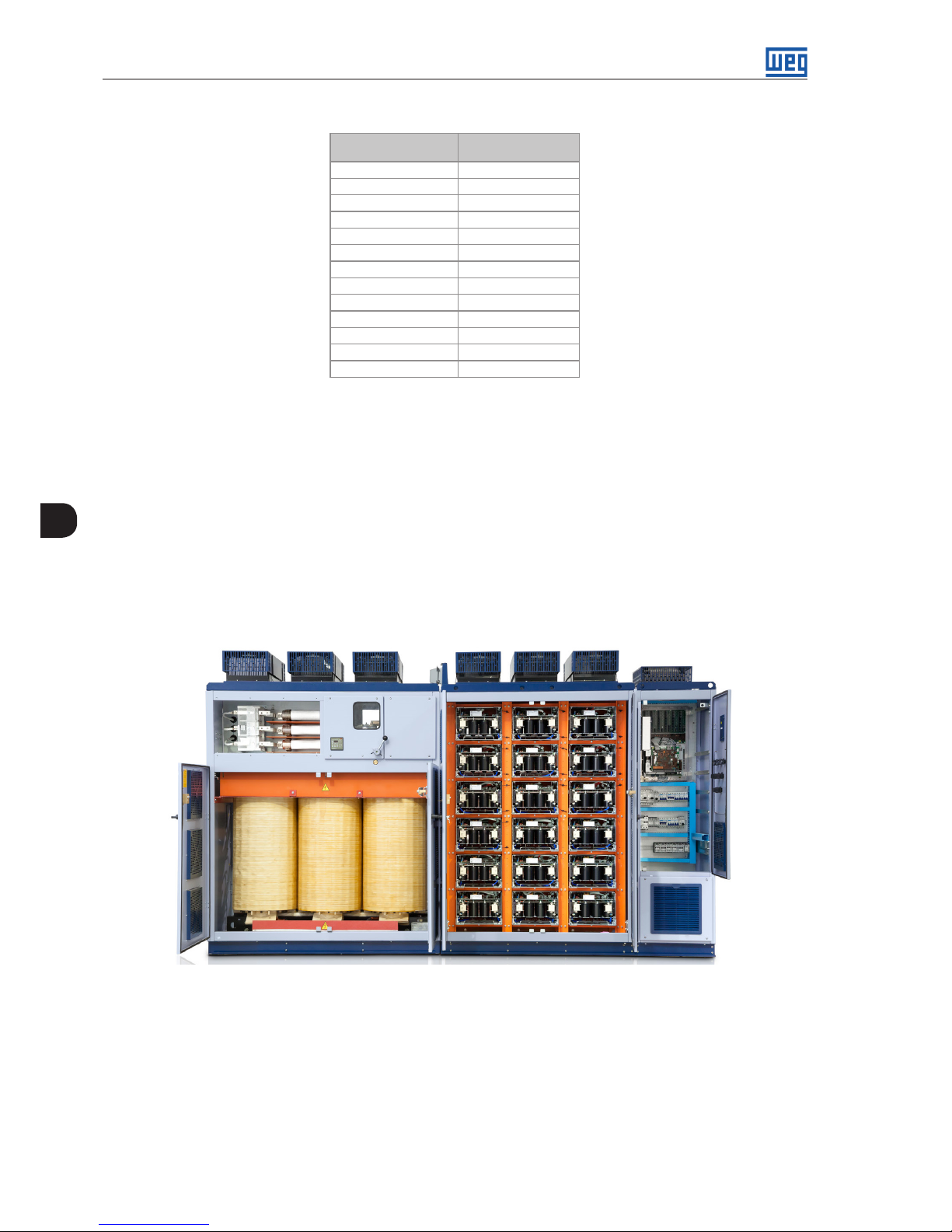
4.1.1 Panel Constructive Aspects
The panel is made with steel sheets painted and processed (cutting, holes, folding, chemical treatment, painting
and finishing) by WEG, ensuring the quality in all the levels of the manufacture process. The inverter parts that
are not painted are zinc plated or have another suitable treatment in order to assure their resistance against
corrosion.
Transformer and Circuit Inverter
Control
Figure 4.2: Panel of the 18-cell MVW3000 (Frame B6)
The MVW3000 panel is supplied, in its standard structure, with degree of protection IP41 (openings smaller than
10 mm and protected against ingress of vertical drops). They can be supplied with distinct degrees of protection
according to the customer’s needs.
The panel cooling is done by means of forced convection. The air enters through the opening on the panel front
doors, goes through the transformer windings and also the power heatsinks located in each power cell. The
hot air leaves through the top do painel, of the panel, where the exhaust fans are located, allowing maintenance
without the need to open the inverter doors.
 Loading...