


CFW110002T5
Table of contents
 Loading...
WEG CFW110002T5, CFW110012T5, CFW110007T5, CFW110004T5, CFW110010T5 User Manual
...
Motors | Automation | Energy | Transmission & Distribution | Coatings
Frequency Inverter
CFW-11 500...690 V
User's Manual

FREQUENCY
INVERTER
MANUAL
Document: 10001473218 / 03
Series: CFW-11
Language: English
Models: 2.9...44 A / 500...600 V
2.9...804 A / 500...690 V
Models with Special DC Hardware: 170...804 A / 500...690 V
02/2016

Summary of Revisions
Version Review Description
- R01 First edition
- R02 General revision
- R03 General revision

Contents
1 SAFETY INSTRUCTIONS .................................................................. 1-1
1.1 SAFETY WARNINGS IN THE MANUAL ......................................................... 1-1
1.2 SAFETY WARNINGS IN THE PRODUCT ........................................................1-1
1.3 PRELIMINARY RECOMMENDATIONS ........................................................... 1-2
2 GENERAL INSTRUCTIONS .............................................................. 2-1
2.1 ABOUT THE MANUAL .................................................................................2-1
2.2 TERMS AND DEFINITIONS .......................................................................... 2-2
2.3 ABOUT THE CFW-11 ................................................................................... 2-5
2.4 IDENTIFICATION LABELS FOR THE CFW-11 ..............................................2-17
2.5 RECEIVING AND STORAGE ....................................................................... 2-19
3 INSTALLATION AND CONNECTION ............................................... 3-1
3.1 MECHANICAL INSTALLATION ..................................................................... 3-1
3.1.1 Installation Environment .................................................................... 3-1
3.1.2 Mounting Considerations ................................................................... 3-2
3.1.3 Cabinet Mounting .............................................................................. 3-7
3.1.4 Installation of the Inverter Hoisting Eyes - Frame Size E ................... 3-10
3.1.5 Installation of the Inverter with Nema1 Kit (Option, CFW11....T...ON1...) on a
Wall - Frame Size E ..............................................................................................3-11
3.1.6 Access to the Control and Power Terminal Strips .............................. 3-11
3.1.7 Removal of the Cable Passage Plate - Frame Sizes D and E .............. 3-14
3.1.8 HMI Installation at the Cabinet Door or
Command Panel (Remote HMI) .................................................................3-14
3.2 ELECTRICAL INSTALLATION ......................................................................3-14
3.2.1 Identification of the Power and Grounding Terminals ....................... 3-15
3.2.2 Power/Grounding Wiring and Fuses ................................................3-20
3.2.3 Power Connections ...........................................................................3-31
3.2.3.1 Input Connections .............................................................. 3-34
3.2.3.1.1 AC Power Supply Considerations ............................ 3-35
3.2.3.1.2 IT Networks ......................................................... 3-35
3.2.3.1.3 Command Fuses of Pre-charge Circuit ................. 3-37
3.2.3.2 Dynamic Braking ................................................................ 3-38
3.2.3.2.1 Sizing the Braking Resistor ..................................3-38
3.2.3.2.2 Installation of the Braking Resistor - Frame Sizes B, C,
D and E .............................................................................. 3-40
3.2.3.3 Output Connections ............................................................ 3-41
3.2.4 Grounding Connections ................................................................... 3-44
3.2.5 Control Connections ......................................................................... 3-45
3.2.6 Typical Control Connections ............................................................. 3-51
3.3 SAFETY STOP FUNCTION .......................................................................... 3-54
3.3.1 Installation ....................................................................................... 3-56
3.3.2 Operation ........................................................................................ 3-57
3.3.2.1 Truth Table .........................................................................3-57
3.3.2.2 State of Inverter, Fault and Alarm Related to Safety Stop
Function ......................................................................................... 3-57
3.3.2.3 STO Status Indication .........................................................3-57
3.3.2.4 Periodic Test ........................................................................ 3-58

Contents
3.3.3 Examples of Wiring Diagrams of Inverter Control Signal ................. 3-59
3.3.4 Technical Specifications .................................................................... 3-60
3.3.4.1 Electrical Control Characteristics ........................................ 3-60
3.3.4.2 Operational Safety Characteristics ...................................... 3-60
3.3.4.3 Certification ........................................................................ 3-61
3.4 INSTALLATION ACCORDING TO THE EUROPEAN DIRECTIVE OF
ELECTROMAGNETIC COMPATIBILITY ..............................................................3-62
3.4.1 Conformal Installation ..................................................................... 3-62
3.4.2 Standard Definitions ........................................................................ 3-63
3.4.3 Emission and Immunity Levels .......................................................... 3-64
4 KEYPAD AND DISPLAY .................................................................... 4-1
4.1 INTEGRAL KEYPAD - HMI-CFW11 ...............................................................4-1
4.2 PARAMETERS ORGANIZATION .................................................................... 4-4
5 FIRST TIME POWER-UP AND START-UP ........................................... 5-1
5.1 PREPARE FOR START-UP .............................................................................. 5-1
5.2 START-UP
5.2.1 Password Setting in P0000 .................................................................5-3
5.2.2 Oriented Start-Up ...............................................................................5-3
5.2.3 Setting Basic Application Parameters .................................................. 5-5
5.3 SETTING DATE AND TIME ........................................................................... 5-9
5.4 BLOCKING PARAMETERS MODIFICATION ................................................. 5-10
5.5 HOW TO CONNECT A PC ......................................................................... 5-10
5.6 FLASH MEMORY MODULE .........................................................................5-10
.................................................................................................... 5-2
6 TROUBLESHOOTING AND MAINTENANCE .................................... 6-1
6.1 OPERATION OF THE FAULTS AND ALARMS .................................................6-1
6.2 FAULTS, ALARMS AND POSSIBLE CAUSES ................................................... 6-2
6.3 SOLUTIONS FOR THE MOST FREQUENT PROBLEMS ...................................6-8
6.4 INFORMATION NECESSARY FOR CONTACTING TECHNICAL SUPPORT ......6-8
6.5 PREVENTIVE MAINTENANCE ...................................................................... 6-9
6.5.1 Cleaning Instructions ....................................................................... 6-10
7 OPTION KITS AND ACCESSORIES ................................................. 7-1
7.1 OPTION KITS .............................................................................................. 7-1
7.1.1 Nema 1 Protection Degree - Frame Sizes B, C and E ..........................7-1
7.1.2 Safety Stop Function ........................................................................... 7-1
7.1.3 24 Vdc External Control Power Supply ...............................................7-1
7.2 ACCESSORIES .............................................................................................7-2
7.2.1 Use of External Dynamic Braking Module DBW03 and DBW04 .......... 7-4
8 TECHNICAL SPECIFICATIONS ........................................................ 8-1
8.1 POWER DATA .............................................................................................. 8-1
8.2 ELECTRONICS/GENERAL DATA ................................................................... 8-7
8.3 CODES AND STANDARDS ........................................................................... 8-8
8.4 CERTIFICATIONS ......................................................................................... 8-8
8.5 MECHANICAL DATA .................................................................................... 8-9
8.6 NEMA 1 KITS ............................................................................................. 8-16
1 SAFETY INSTRUCTIONS
This manual provides information for the proper installation and
operation of the CFW-11 frequency inverter.
Only trained and qualified personnel should attempt to install,
start-up, and troubleshoot this type of equipment.
1.1 SAFETY WARNINGS IN THE MANUAL
The following safety warnings are used in this manual:
DANGER!
The procedures recommended in this warning have the purpose of protecting the user against death,
serious injuries and considerable material damage.
Safety Instructions
1
DANGER!
Les procédures concernées par cet avertissement sont destinées à protéger l'utilisateur contre des
dangers mortels, des blessures et des détériorations matérielles importantes.
ATTENTION!
The procedures recommended in this warning have the purpose of avoiding material damage.
NOTE!
The information mentioned in this warning is important for the proper understanding and good
operation of the product.
1.2 SAFETY WARNINGS IN THE PRODUCT
The following symbols are attached to the product and require special attention:
Indicates a high voltage warning.
Electrostatic discharge sensitive components.
Do not touch them.
Indicates that a ground (PE) must be connected securely.
Indicates that the cable shield must be grounded.
Indicates a hot surface warning.
CFW-11 | 1-1
1
Safety Instructions
1.3 PRELIMINARY RECOMMENDATIONS
DANGER!
Only trained personnel, with proper qualifications, and familiar with the CFW-11 and associated
machinery shall plan and implent the installation, starting, operation, and maintenance of this
equipment.
The personnel shall follow all the safety instructions described in this manual and/or defined by the
local regulations.
Failure to comply with the safety instructions may result in death, serious injury, and equipment damage.
DANGER!
Seulement personnes avec la qualification adéquate et familiarisation avec le CFW-11 et équipements
associés doivent planifiquer ou implementer l'installation, mise en marche, operation et entretien
de cet équipement.
Cettes personnes doivent suivre toutes les instructions de sécurités indiquées dans ce manuel, et/ou
définies par normes locales.
L'inobservance des instructions de sécurité peut résulter en risque de vie et/ou dommages de cet
équipement.
NOTE!
For the purpose of this manual, qualified personnel are those trained and able to:
1. Install, ground, power-up, and operate the CFW-11 according to this manual and to the current
legal safety procedures.
2. Use the protection equipment according to the established regulations.
3. Provide first aid.
DANGER!
Always disconnect the main power supply before touching any electrical device associated with the
inverter.
Several components may remain charged with high voltage and/or in movement (fans), even after
the AC power supply has been disconnected or turned off.
Wait at least 10 minutes to guarantee the fully discharge of capacitors.
Always connect the equipment frame to the ground protection (PE).
DANGER!
Débranchez toujours l'alimentation principale avant d'entrer en contact avec un appareil électrique
associé au variateur. Plusieurs composants peuvent rester chargés à un potentiel électrique élevé et/
ou être en mouvement (ventilateurs), même après la déconnexion ou la coupure de l'alimentation
en courant alternatif.
Attendez au moins 10 minutes que les condensateurs se déchargent complètement.
Raccordez toujours la masse de l'appareil à une terre protectrice (PE).
1-2 | CFW-11
Safety Instructions
ATTENTION!
The electronic boards contain components sensitive to electrostatic discharges. Do not touch the
components and terminals directly. If needed, touch first the grounded metal frame or wear an
adequate ground strap.
Do not perform a withstand voltage test on any part of the inverter!
If needed, please, consult WEG.
NOTE!
Frequency inverters may cause interference in other electronic devices. Follow the recommendations
listed in Chapter 3 INSTALLATION AND CONNECTION on page 3-1, to minimize these effects.
NOTE!
Fully read this manual before installing or operating the inverter.
1
DANGER!
Crushing Hazard
In order to ensure safety in load lifting applications, electric and/or mechanical devices must be
installed outside the inverter for protection against accidental fall of load.
DANGER!
This product was not designed to be used as a safety element. Additional measures must be taken
so as to avoid material and personal damages.
The product was manufactured under strict quality control, however, if installed in systems where its
failure causes risks of material or personal damages, additional external safety devices must ensure
a safety condition in case of a product failure, preventing accidents.
DANGER!
Risque d'écrasement
Afin d'assurer la sécurité dans les applications de levage de charges, les équipements électriques et/
ou mécaniques doivent être installés hors du variateur pour éviter une chute accidentelle des charges.
DANGER!
Ce produit n'est pas conçu pour être utilisé comme un élément de sécurité. Des précautions
supplémentaires doivent être prises afin d'éviter des dommages matériels ou corporels.
Ce produit a été fabriqué sous un contrôle de qualité conséquent, mais s'il est installé sur des systèmes
où son dysfonctionnement entraîne des risques de dommages matériels ou corporels, alors des
dispositifs de sécurité externes supplémentaires doivent assurer des conditions de sécurité en cas de
défaillance du produit, afin d'éviter des accidents.
CFW-11 | 1-3

1
Safety Instructions
1-4 | CFW-11
General Instructions
2 GENERAL INSTRUCTIONS
2.1 ABOUT THE MANUAL
This manual exposes how to install, to start-up in V/f (scalar) mode,
the main characteristics and shows how to troubleshoot the most
common problems of the 500...600 V and 500...690 V models
of CFW-11 inverter series.
It is also possible to operate the CFW-11 in the following control modes: VV W, Sensorless Vector and Vector
with Encoder. For further details on the inverter operation with other control modes, refer to the programming
manual.
ATTENTION!
The operation of this equipment requires installation instructions and detailed operation provided in
the user's manual, programming manual and manuals/guides for kits and accessories.
The user's manual and the parameters quick reference are supplied in a hard copy together with the
inverter. The user guides are also provided in a hard copy along with the kit/accessories. The other
manuals are available at www.weg.net.
A printed copy of the files available on WEG’s website can be requested at your local WEG dealer.
2
For information on other functions, accessories, and communication, please refer to the following manuals:
Programming manual, with a detailed description of the parameters and advanced functions of the CFW-11.
Incremental encoder interface module manual.
I/O expansion module manual.
RS232/RS485 Serial communication manual.
CANopen Slave communication manual.
Anybus-CC communication manual.
DeviceNet communication manual.
Ethercat communication manual.
Profibus DP communication manual.
Symbinet communication manual.
SoftPLC manual.
CFW-11 | 2-1

General Instructions
2.2 TERMS AND DEFINITIONS
2
Normal Duty Cycle (ND): the duty cycle that defines the steady state current value I
and an overload of
nom-ND
110 % during 1 minute. It is selected by programming P0298 (Application) = 0 (Normal Duty - ND). It must
be used for driving motors that are not subject in that application to high torques with respect to their rated
torque, when operating at constant speed, during start, acceleration or deceleration.
I
: inverter rated current for use with normal duty cycle (ND = Normal Duty).
nom-ND
Overload: 1.1 x I
Heavy Duty Cycle (HD): the duty cycle that defines the steady state current value I
/ 1 minute.
nom-ND
and an overload of
nom-HD
150 % during 1 minute. It is selected by programming P0298 (Application) = 1 (Heavy Duty - HD). It must be
used for driving motors that are subject in that application to high torques with respect to their rated torque,
when operating at constant speed, during start, acceleration or deceleration.
I
: inverter rated current for use with heavy duty cycle (HD = Heavy Duty).
nom-HD
Overload: 1.5 x I
/ 1 minute.
nom-HD
Rectier: the input circuit of the inverters that converts the input AC voltage into DC; it is made of thyristors
and power diodes.
Pre-charge Circuit: it charges the DC link capacitors with a limited current, thus avoiding higher current peaks
when powering the inverter.
DC Link: inverter intermediate circuit; DC voltage obtained from the rectification of the AC input voltage or
from an external power supply. It feeds the inverter output IGBTs bridge.
U, V, W Arms: set of two IGBTs forming the inverter output phases U, V, and W.
IGBT: Insulated Gate Bipolar Transistor; it is the output inverter bridge basic component, working as an electronic
switch either in the saturated (closed switch) or in the cut off mode (open switch).
Braking IGBT: works as a switch to activate the braking resistors; it is controlled by the DC bus voltage level.
Gate Driver: circuit used to turn-on and turn-off the IGBTs.
PWM: Pulse Width Modulation; a pulsed voltage that feeds the motor.
Switching Frequency: it is the inverter bridge IGBTs commutation frequency, normally specified in kHz. Also
known as carrier frequency.
Heatsink: It is a metal part designed for dissipating the heat generated by the power semiconductors.
PE: Protective Earth.
MOV: Metal Oxide Varistor.
RFI Filter: Radio-Frequency Interference Filter; a filter that avoids interference in the radiofrequency range.
2-2 | CFW-11

General Instructions
PTC: it is a resistor, whose resistance value in ohms increases proportionally to the temperature increase, being
used as temperature sensor in motors.
NTC: it is a resistor, whose resistance value in ohms decreases proportionally to the temperature increase, being
used as temperature sensor in power modules.
HMI: Human-Machine Interface; it is the device that allows the control of the motor, the visualization and the
modification of the inverter parameters; it's also known as keypad. The CFW-11 HMI presents keys for
commanding the motor, navigation keys and a graphic LCD display.
FLASH Memory: it is the nonvolatile memory that can be electrically written and erased.
RAM Memory: Random Access Memory (volatile).
USB: Universal Serial Bus; it's a serial bus standard that allows devices to be connected using the Plug and
Play concept.
General Enable: when activated, it accelerates the motor via acceleration ramp. When deactivated, this
function immediately blocks the PWM pulses. The general enable function can be controlled through a digital
input programmed for this function or via serial communication.
Run/Stop: inverter function that when activated (Run) accelerates the motor with the acceleration ramp until
reaching the speed reference, and when deactivated (Stop) decelerates the motor with the deceleration ramp
down to stop. It can be commanded through a digital input programmed for that function or via serial
communication. The HMI keys
STO: Safe Torque Off; functional safety function available as an option in CFW-11 inverter series. When STO
function is enabled the inverter guarantees that there is no movement of the motor shaft. It's also called safety
stop function in CFW-11 documentation.
PLC: Programmable Logic Controller.
(Run) and (Stop) work in a similar manner.
2
TBD: value to be defined.
ac: alternated current.
dc: direct current.
Amp, A: ampere.
°C: Celsius degree.
CFM: Cubic Feet per Minute; unit of flow.
cm: centimeter.
°F: Fahrenheit degree.
Hz: hertz.
CFW-11 | 2-3

General Instructions
ft: foot.
hp: horse power = 746 watts; unit of power, used to indicate the mechanical power of electrical motors.
in: inch.
kg: kilogram = 1000 grams.
kHz: kilohertz = 1000 hertz.
l/s: liters per second.
2
lb: pound.
m: meter.
mA: miliampere = 0.001 ampere.
min: minute.
mm: millimeter.
ms: millisecond = 0.001 seconds.
N.M: newton meter; unit of torque.
rms: root mean square; effective value.
rpm: revolutions per minute; unit of speed.
s: second.
V: volts.
Ω: ohms.
2-4 | CFW-11

General Instructions
2.3 ABOUT THE CFW-11
The CFW-11 frequency inverter is a high performance product designed for speed and torque control of
three-phase induction motors. The main characteristic of this product is the "Vectrue" technology, which has the
following advantages:
Scalar control (V/f), VVW or vector control programmable in the same product.
The vector control may be programmed as "sensorless" (which means standard motors without using encoders)
or as "vector control" with the use of an encoder.
The "sensorless" control allows high torque and fast response, even in very low speeds or at the starting.
The "vector with encoder" control allows high speed precision for the whole speed range (even with a standstill
motor).
"Optimal Braking" function for the vector control, allowing the controlled braking of the motor and avoiding
the use of the braking resistor in some applications.
"Self-Tuning" feature for vector control. It allows the automatic adjustment of the regulators and control
parameters from the identification (also automatic) of the motor parameters and load.
2
CFW-11 | 2-5

2
General Instructions
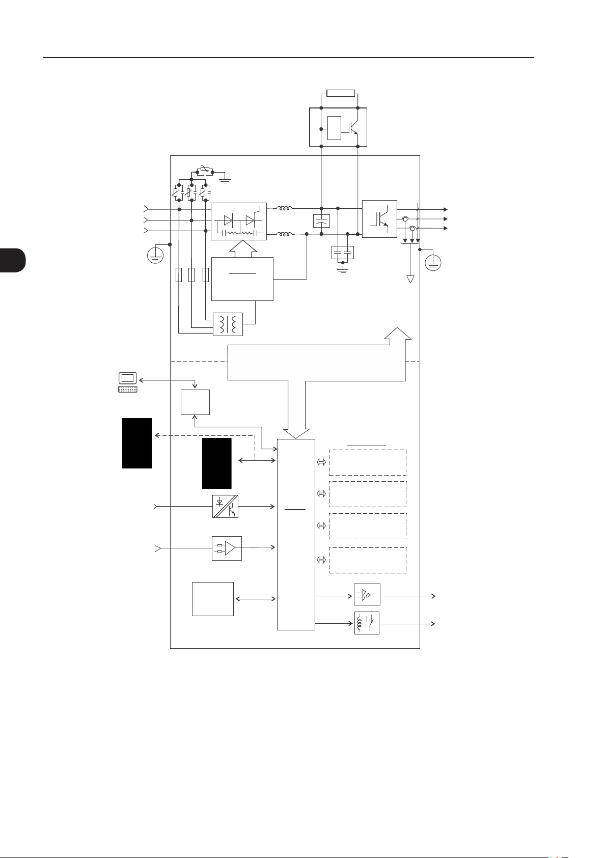
R/L1
Power supply
PC
S/L2
T/L3
PE
RFI filter/MOVs
Three-phase
rectifier
Pre-
charge
(*)
DC Link
chokes
capacitor bank
DC+ DC-BR
DC Link
Power
Control
RFI filter
= DC bus connection
= braking resistor connection
U/T1
V/T2
Motor
W/T3
Inverter
with IGBT
(*)
transistors
PE
Feedback:
- voltage
- current
SuperDrive G2 software
WLP software
Keypad (remote)
Digital inputs
(DI1 to DI6)
Analog inputs
(AI1 and AI2)
(*) The capacitor of RFI filter and MOV connected to the ground must be disconnected with IT network, high impedance grounding network and cornergrounded delta networks. Refer to item Item 3.2.3.1.2 IT Networks on page 3-35.
Figure 2.1 - Block diagram for the CFW -11 - frame sizes B and C
USB
FLASH
memory
module
MMF-03
Control power supply and interfaces
between power and control
Keypad
CC11
Control
board with
a 32 bits
"RISC"
CPU
Encoder interface
(anybus) (Slot 4 )
Accessories
I/O expansion
(Slot 1 - white)
(Slot 2 - yellow)
COMM 1
(Slot 3 - green)
COMM 2
Analog outputs
(AO1 and AO2)
Digital outputs
DO1 (RL1) to
DO3 (RL3)
2-6 | CFW-11
General Instructions
C
A
A - mounting supports
(for through the wall mounting)
B - heatsink
C - top cover
D - fan with mounting support
E - COMM 2 module (anybus)
F - option board/accessory module
G - FLASH memory module MMF-03
H - front cover
I - keypad
J - SRB2A safety stop board
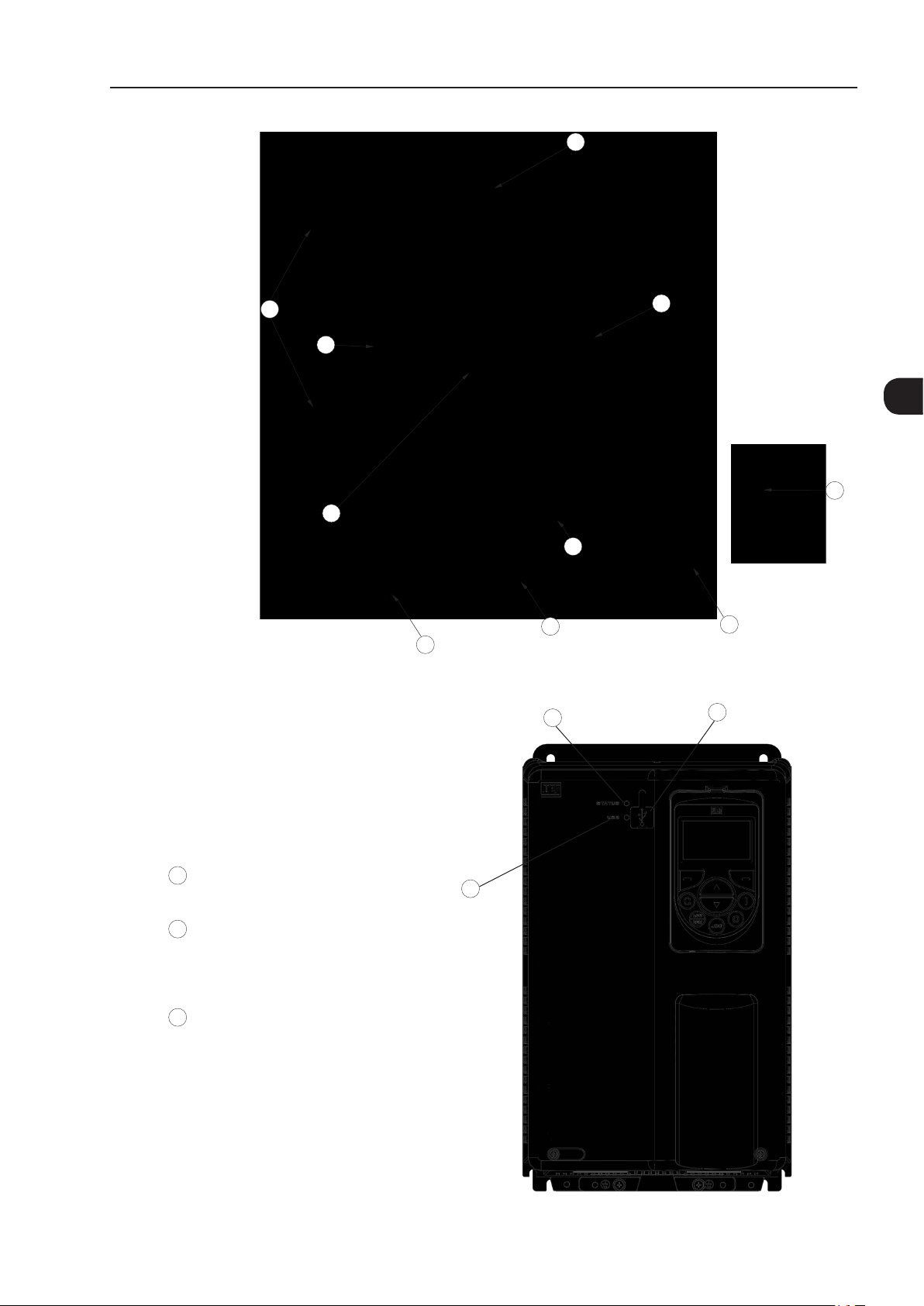
Figure 2.2 - Main components of the CFW-11 - frame sizes B and C
G
B
2
I
J
F
E
D
3
H
1
USB connector
1
USB LED
2
Off: no USB connection
On/Flashing: USB communication is active
3
STATUS LED
Green: normal operation with no fault or alarm
Yellow: alarm condition
Flashing red: fault condition
Figure 2.3 - LEDs and USB connector
2
CFW-11 | 2-7

2
General Instructions
R/L1
Power supply
PC
S/L2
T/L3
PE
RFI filter/MOVs
Three-phase
rectifier
Pre-
charge
(*)
DC Link
chokes
capacitor bank
DC+ DC-BR
DC Link
Power
Control
RFI filter
= DC bus connection
= braking resistor connection
U/T1
V/T2
Motor
W/T3
Inverter
with IGBT
transistors
PE
Feedback:
- voltage
- current
SuperDrive G2 software
WLP software
Keypad (remote)
Digital inputs
(DI1 to DI6)
Analog inputs
(AI1 and AI2)
(*) The capacitor of RFI filter and MOV connected to the ground must be disconnected with IT network, high impedance grounding network and corner-
-grounded delta networks. Refer to Item 3.2.3.1.2 IT Networks on page 3-35.
Figura 2.4 - Block diagram for the CFW -11 - frame sizes D and E
USB
FLASH
memory
module
MMF-03
Control power supply and interfaces
between power and control
Keypad
CC11
Control
board with
a 32 bits
"RISC"
CPU
Encoder interface
(anybus) (Slot 4 )
Accessories
I/O expansion
(Slot 1 - white)
(Slot 2 - yellow)
COMM 1
(Slot 3 - green)
COMM 2
Analog outputs
(AO1 and AO2)
Digital outputs
DO1 (RL1) to
DO3 (RL3)
2-8 | CFW-11
General Instructions
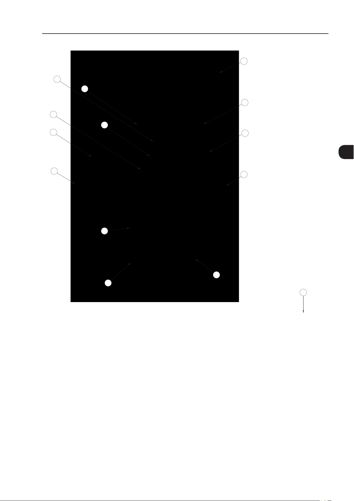
I
D
L
J
E
C
B
K
2
A
F
H
G
Inverter with Nema1 kit
(option - only frame size E)
I
M
A - keypad
B - control rack cover
C - CC11 control board
D - FLASH memory module MMF-03
E - control accessory module (refer to the Section 7.2 ACCESSORIES on page 7-2)
F - Anybus-CC accessory module (refer to the Section 7.2 ACCESSORIES on page 7-2)
G - bottom front cover
H - heatsink fan
I - mounting supports (for through the wall mounting)
J - hoisting eye
K - rear part of the inverter (external part for flange mounting)
L - SRB4 safety stop board
M - Nema1 kit - only frame size E
Figure 2.5 - Main components of the CFW-11 - frame sizes D and E
CFW-11 | 2-9
General Instructions
Power
supply
R/L1
S/L2
T/L3
RFI filter/MOVs
Three-phase
rectifier
External braking
module
(Optional)
(*)
DC+
Braking
resistor
DC-
U/T1
V/T2
W/T3
Motor
2
PE
PC
SuperDrive G2 software
WLP software
Keypad (remote)
Digital inputs
(DI1 to DI6)
Analog inputs
(AI1 and AI2)
Power
Control
USB
chokes
CPC 11
Pre-charge
control
Keypad
DC Link
Control power supply and interfaces
between power and control sections
CC11
Control
board with
32-bit
"RISC"
CPU
bank
DC link capacitor
Encoder interface
IGBT
inverter
RFI filter
Accessories
I/O expansion
(Slot 1 - white)
(Slot 2 - yellow)
COMM 1
(Slot 3 - green)
COMM 2
(anybus) (Slot 4)
PE
Feedback:
- voltage
- current
FLASH
memory
module
MMF-03
(*) The capacitor of RFI filter and MOV connected to the ground must be disconnected with IT network, high impedance grounding network and cornergrounded delta networks. Refer to Item 3.2.3.1.2 IT Networks on page 3-35.
(a) Frame sizes F and G CFW-11 block diagram - Standard models with alternating current feeding
Analog outputs
(AO1 and AO2)
Digital outputs
DO1 (RL1) to
DO3 (RL3)
2-10 | CFW-11

DC supply
General Instructions
PC
SuperDrive G2 software
WLP software
Keypad (remote)
Digital inputs
(DI1 to DI6)
Analog inputs
(AI1 and AI2)
Power
Control
USB
DC+
DC Link capacitor bank
Control power supply and interfaces
between power and control sections
Keypad
CC11
CC11
Control
board with
32-bit
"RISC" CPU
DC-
IGBT
inverter
Feedback:
- voltage
RFI filter
Accessories
I/O expansion
(Slot 1 - white)
Encoder interface
(Slot 2 - yellow)
COMM 1
(Slot 3 - green)
(anybus) (Slot 4)
- current
COMM 2
U/T1
V/T2
W/T3
PE
Motor
2
FLASH
memory
module
MMF-03
(b) Frame sizes F and G CFW-11 block diagram - Models with DC voltage feeding (Special DC Hardware)
Figure 2.6 - (a) and (b) - Block diagram for the CFW-11 - frame sizes F and G
Analog outputs
(AO1 and AO2)
Digital outputs
DO1 (RL1) to
DO3 (RL3)
CFW-11 | 2-11
2
General Instructions
K
I
J
D
C
L
B
A
I
H
A - keypad
B - control rack cover
C - CC11 control board
D - FLASH memory module MMF-03
E - control accessory module
F - Anybus-CC accessory module
G - bottom front cover
H - bheatsink fan
I - mounting supports (for surface mounting)
J - hoisting eye
K - rear part of the inverter (external part for flange mounting)
L - SRB3 safety stop board
E
F
G
2-12 | CFW-11
Figure 2.7 - CFW-11 main components - frame sizes F and G
External braking
module
(Accessory)
General Instructions
Braking
resistor
Power
supply
SuperDrive G2 software
WLP software
R/L1
S/L2
T/L3
PE
PC
RFI filter/MOVs
Three-phase
Rectifier
Pre-charge
Power
Control
USB
(*)
CPC 11
control
Control power supply and interfaces
between power and control sections
DC+
RFI filter
DC Link capacitor bank
DC-
IGBT
inverter
Feedback:
- voltage
- current
U/T1
V/T2
W/T3
PE
Motor
2
Accessories
I/O expansion
(Slot 1 - white)
Keypad (remote)
Digital inputs
(DI1 to DI6)
Analog inputs
(AI1 and AI2)
FLASH
memory
module
MMF-03
(*) The RFI filter capacitor and MOV connected to the ground must be disconnected with IT and corner-grounded delta networks. Refer to Item 3.2.3.1.2
IT Networks on page 3-35.
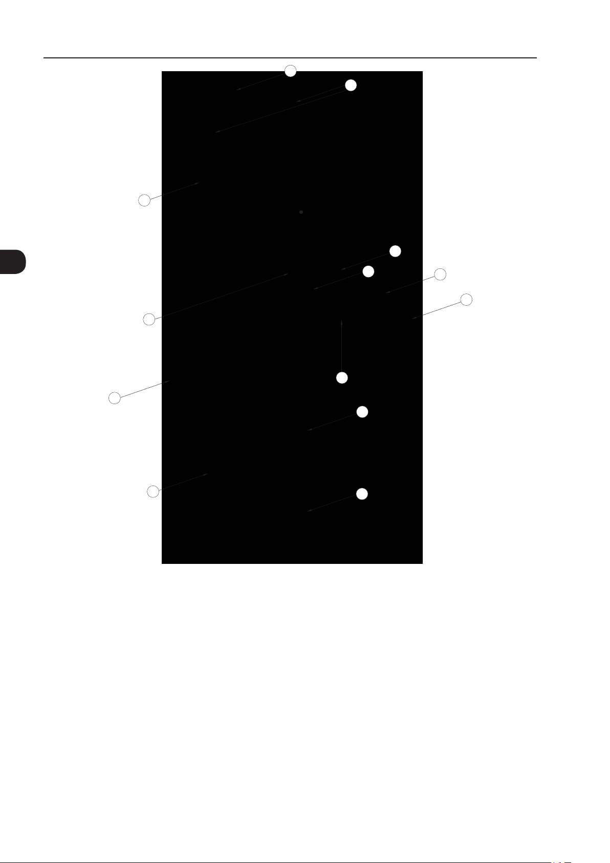
Figure 2.8 - Block diagram of standard models of CFW-11 frame size H (584 A and 625 A models) with alternating current
Keypad
CC11
Control
board with
32-bit
"RISC" CPU
feeding
Encoder interface
(Slot 2 - yellow)
COMM 1
(Slot 3 - green)
COMM 2
(anybus) (Slot 4)
Analog outputs
(AO1 and AO2)
Digital outputs
DO1 (RL1) to
DO3 (RL3)
CFW-11 | 2-13
2
General Instructions
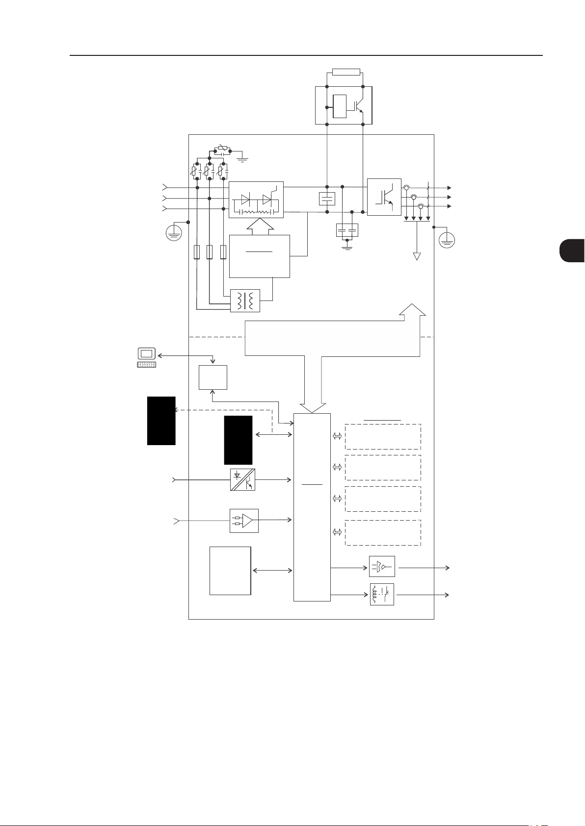
R1/L1-1
Power
S1/L2-1
supply
T1/L3-1
PE
RFI filter/MOVs
Three-phase
rectifier
CPC 11-1
Pre-charge
External braking
module
(Accessory)
(*)
control
Braking resistor
DC+
DC Link capacitor bank
DC-
IGBT
inverter
RFI filter
Feedback:
- voltage
- current
U/T1
V/T2
W/T3
Motor
PE
RFI filter/MOVs
R2/L1-2
Power
S2/L2-2
supply
T2/L3-2
PE
Power
PC
SuperDrive G2 software
WLP software
Keypad (remote)
Digital inputs
(DI1 to DI6)
Analog inputs
(AI1 and AI2)
(*) The capacitor of RFI filter and MOV connected to the ground must be disconnected with IT network, high impedance grounding network and
corner-grounded delta networks. Refer to Item 3.2.3.1.2 IT Networks on page 3-35.
Figure 2.9 - Block diagram of standard models of CFW-11 frame size H (758 A and 804 A models) with alternating current
Control
USB
FLASH
memory
module
MMF-03
(*)
Three-phase
rectifier
CPC 11-2
Pre-charge
control
Keypad
Control power supply and interfaces
between power and control sections
Accessories
I/O expansion
(Slot 1 - white)
Encoder interface
CC11
Control
board with
32-bit
"RISC" CPU
(Slot 2 - yellow)
COMM 1
(Slot 3 - green)
COMM 2
(anybus) (Slot 4)
Analog outputs
(AO1 and AO2)
Digital outputs
DO1 (RL1) to
DO3 (RL3)
2-14 | CFW-11

DC power supply
General Instructions
PC
SuperDrive G2 software
WLP software
Keypad (remote)
Digital inputs
(DI1 to DI6)
Analog inputs
(AI1 and AI2)
Power
Control
USB
DC+
DC Link capacitor bank
Control power supply and interfaces
between power and control sections
Keypad
CC11
Control
board with
32-bit
"RISC" CPU
DC-
RFI filter
IGBT
inverter
Feedback:
- voltage
- current
Accessories
I/O expansion
(Slot 1 - white)
Encoder interface
(Slot 2 - yellow)
COMM 1
(Slot 3 - green)
COMM 2
(anybus) (Slot 4)
U/T1
V/T2
W/T3
Motor
PE
2
FLASH
memory
module
MMF-03
Figure 2.10 - Block diagram of CFW-11 frame size H models with DC voltage feeding (special hardware DC)
Analog outputs
(AO1 and AO2)
Digital outputs
DO1 (RL1) to
DO3 (RL3)
CFW-11 | 2-15
General Instructions
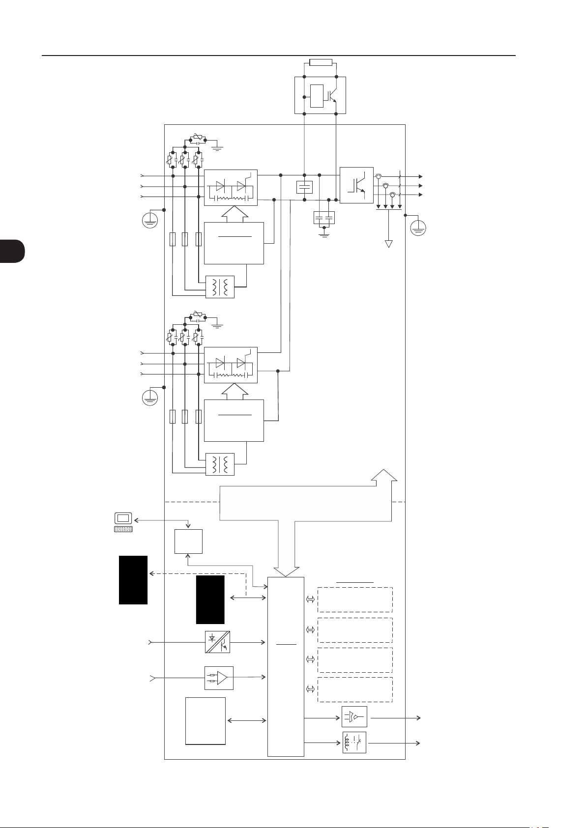
K
I
J
2
D
C
L
E
M
F
I
B
A
G
H
A - keypad
B - control rack cover
C - CC11 control board
D - FLASH memory module MMF-03
E - control accessory module
F - Anybus-CC accessory module
G - bottom front cover
H - heatsink fan
I - mounting supports (for surface mounting)
J - hoisting eye
K - rear part of the inverter (external part for flange mounting)
L - SRB3 safety stop board
M - shield for the control cables
Figure 2.11 - CFW-11 main components - frame size H
2-16 | CFW-11
General Instructions
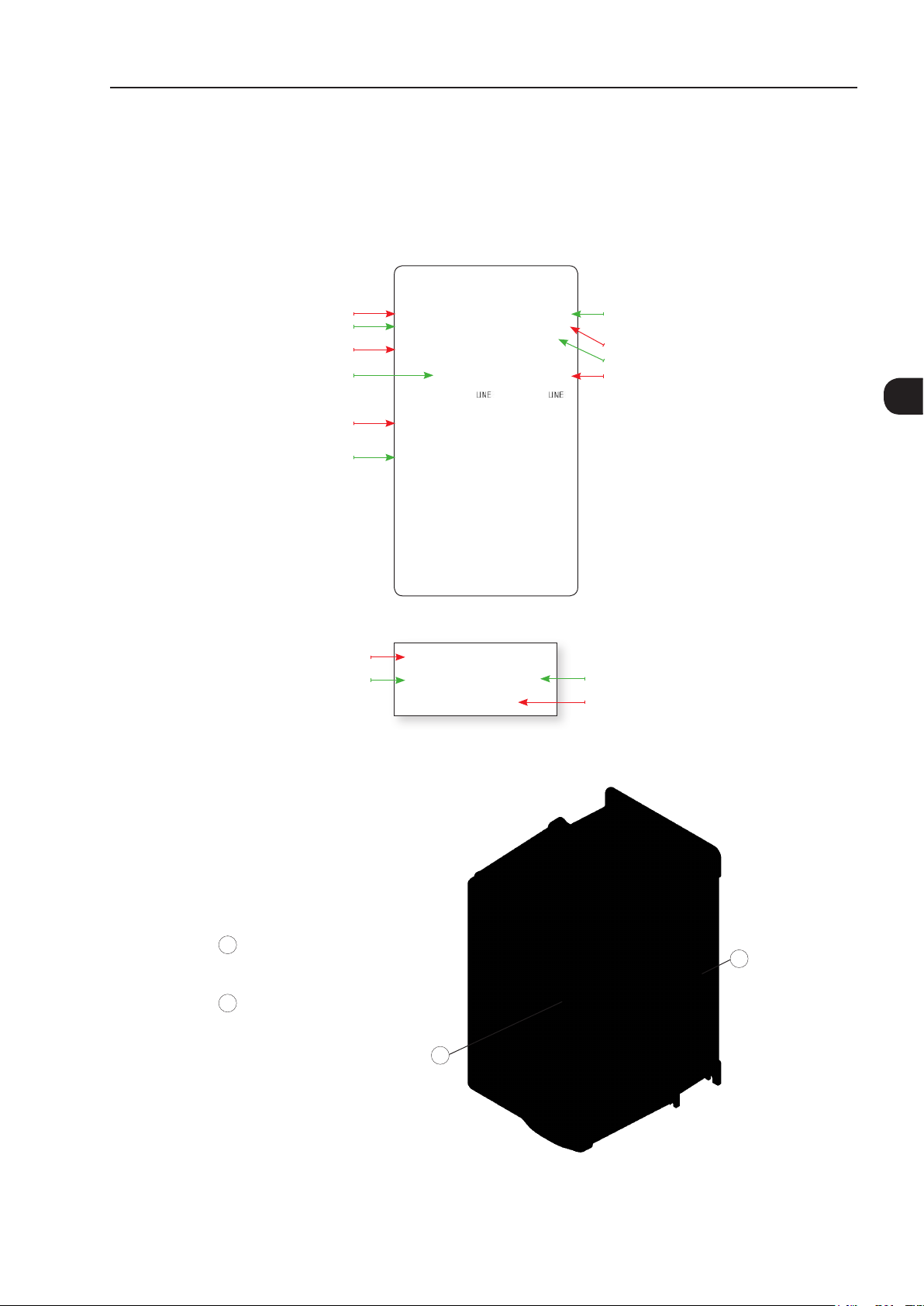
2.4 IDENTIFICATION LABELS FOR THE CFW-11
There are two nameplates on the CFW-11: one complete nameplate is affixed to the side of the inverter and
a simplified one is located under the keypad. The nameplate under the keypad allows the identification of the
most important characteristics of the inverter even if they are mounted side-by-side.
CFW-11 model
WEG part number
Inverter net weight
Rated input data (voltage, number of phases,
rated currents for operation with ND and HD
overload cycles, frequency)
Current specifications for operation with
normal overload cycle (ND)
Current specifications for operation with
heavy overload cycle (HD)
CFW-11 model
WEG part number
Manufacturing date (48 corresponds
to week and H to year)
Serial number
Maximum surrounding air temperature
Rated output data (voltage, number of phases,
rated currents for operation with ND and HD
overload cycles, over load currents for 1 min
and 3 s, frequency range)
(a) Nameplate afxed to the side of the inverter
BRCFW110044T6OYZ
11799018
SERIAL#:
(b) Nameplate located under the keypad
Figure 2.12 - (a) and (b) - Nameplates
1013933619
48 H
Manufacturing date
(48 corresponds to
week and H to year)
Serial number
2
Nameplate affixed to the side of the
1
heatsink
Nameplate under the keypad
2
Figure 2.13 - Location of the nameplates
1
2
CFW-11 | 2-17

General Instructions
2
Character
that
identifies
the code
end
Special
software
Special
hardware
power supply for
control
Blank =
standard
E.g.:
S1 =
Blank =
standard
DC= feeding
with DC (only
Blank =
standard (not
available)
W = 24 Vdc
Blank =
standard (Safety
Stop function is
not available)
Blank =
standard
internal
RFI filter
(3)
NB =
without
Blank =
standard
special
software #1
valid for frame
sizes F and G)
H1 = special
hardware #1
external power
supply for control
Y = Safety
Stop according
to EN-954-1
category 3
(5)
NF =
without
RFI filter
(4)
braking
IGBT
(2)
IC = no
keypad
Blank =
standard
(6)
(7)
(1)
N1 = Nema1
Refer to Chapter 7 OPTION KITS AND ACCESSORIES on page 7-1, to check option kit availability for each inverter model
Option kit Enclosure type Keypad (HMI) Braking RFI filter Safety stop 24 Vdc external
Power supply
voltage
Number of
power phases
21 = IP21
Blank =
standard
S =
standard
product
O =
(8)
(9)
6 = 500...690 V
5 = 500...600 V
T = three-
phase power
supply
Inverter Model Available Option Kits (Can Be Installed in the Product from the Factory)
Rated
output
current for
use with
the Normal
Duty (ND)
cycle
According
Table 8.1
on page
8-2 and
(blind cover)
product
with option
kit
Table 8.3
on page
8-4
Refer to Chapter 8 TECHNICAL SPECIFICATIONS on page
8-1, for a list of models for the CFW-11 series and for a
complete inverter's technical specification
HOW TO CODIFY THE CFW-11 MODEL (CODIFICATION)
2-18 | CFW-11
Example BR CFW11 0044 T 6 S _ _ _ _ _ _ _ _ _ _ _ _ _ _ _ _ Z
WEG
Market
Field
CFW-11
frequency
inverter
series
identification
(defines
the manual
language and
description
the factory
settings)
2 characters
Available
options
(1) Standard for frame sizes B and C: IP21.
Standard for frame size D: IP20/NEMA1.
Standard for frame sizes E, F, G and H: IP20.
Standard for frame sizes F, G and H with special hardware DC: IP00.
(2) Standard keypad (HMI-CFW11).
(3)Braking transistor (IGBT) is incorporated in all models of frame sizes B, C, D, and E as standard.
(4) Only valid for frame sizes D and E.
(5) Only valid for frame sizes B, C and D.
(6) Only valid for frame sizes B, C, D and E.
(7) Only valid for frame sizes D, E, F and G.
(8) Only valid for frame sizes B and C.
(9) Only valid for frame sizes D, E, F, G and H.
General Instructions
2.5 RECEIVING AND STORAGE
The CFW-11 is packaged and shipped in a cardboard box for models of frames B, and C.
The frame sizes D, E, F, G and H models are supplied packed in wooden boxes.
There is an identification label affixed to the outside of the package, identical to the one affixed to the side of
the inverter.
To open the package:
1. Remove the package front cover.
2. Take out the polystyrene foam protection.
Verify whether:
1. The CFW-11 nameplate corresponds to the purchased model.
2. Any damage occurred during transportation.
Report any damage immediately to the carrier that delivered your CFW-11 inverter.
If the CFW-11 is not installed soon, store it in a clean and dry location (temperature between -25 °C and 60 °C
(-13 °F and 140 °F), with a cover to prevent dust accumulation inside it.
ATTENTION!
When the inverter is stored for a long period, it becomes necessary to perform the capacitor reforming.
Refer to the procedure in the Section 6.5 PREVENTIVE MAINTENANCE on page 6-9 in the Table
6.3 on page 6-9.
2
CFW-11 | 2-19

2
General Instructions
2-20 | CFW-11
Loading...