

Page 1

Safety Stop Function
Función Parada Segura
Função de Parada de Segurança
CFW-11, CFW-11M, CFW70X
Installation, Configuration and Operation Guide
Guía de Instalación, Configuración y Operación
Guia de Instalação, Configuração e Operação
Motors | Automation | Energy | Transmission & Distribution | Coatings
Page 2

Page 3

Summary / Índice
ENGLISH
1. GENERAL INFORMATION ..................................................................................................5
2. INSTALLATION .....................................................................................................................8
3. OPERATION ........................................................................................................................10
3.1 Truth Table ............................................................................................................................... 10
3.2 State of Inverter, Fault and Alarm Related to Safety Stop Function .................................. 10
3.3 STO Status Indication ............................................................................................................ 11
3.4 Periodic Test............................................................................................................................ 11
4. EXAMPLES OF WIRING DIAGRAMS OF INVERTER CONTROL SIGNAL ...................12
5. TECHNICAL SPECIFICATIONS ........................................................................................13
5.1 Electrical Control Characteristics ......................................................................................... 13
5.2 Operational Safety Characteristics ...................................................................................... 13
APPENDIX .............................................................................................................................. 32
ESPAÑOL
1. INFORMACIONES GENERALES ......................................................................................14
2. INSTALACIÓN ....................................................................................................................17
3. PUESTA EN MARCHA .......................................................................................................19
3.1 Tabla-Verdad ........................................................................................................................... 19
3.2 Estado del Convertidor de Frecuencia, Fallos y Alarmas Relacionados a la Función de
Parada de Seguridad .................................................................................................................... 19
3.3 Señalización del estado de la función “Safety Stop” .......................................................... 20
3.4 Teste Periódico .......................................................................................................................20
4. EJEMPLOS DE DIAGRAMAS DE CONEXIÓN DE LAS SEÑALES DE CONTROL DEL
CONVERTIDOR ......................................................................................................................21
5. ESPECIFICACIONES TÉCNICAS .................................................................................... 22
5.1 Características Eléctricas de Control ................................................................................... 22
5.2 Características de Seguridad Operacional .......................................................................... 22
ANEXO .................................................................................................................................... 32
PORTUGUÊS
1. INFORMAÇÕES GERAIS .................................................................................................. 23
2. INSTALAÇÃO ..................................................................................................................... 26
3. COLOCANDO EM FUNCIONAMENTO ........................................................................... 28
3.1 Tabela-Verdade ....................................................................................................................... 28
3.2 Estado do Inversor, Falha e Alarme Relacionados à Função de Parada de Segurança .28
3.3 Indicação do Estado da Função Safety Stop....................................................................... 29
3.4 Teste Periódico .......................................................................................................................29
4. EXEMPLOS DE ESQUEMAS DE LIGAÇÃO DOS SINAIS DE CONTROLE DO
INVERSOR ............................................................................................................................. 30
5. ESPECIFICAÇÕES TÉCNICAS .........................................................................................31
5.1 Características Elétricas de Controle ................................................................................... 31
5.2 Características de Segurança Operacional ......................................................................... 31
ANEXO .................................................................................................................................... 32
Page 4

Page 5
Safety Stop Function
CFW-11, CFW-11M, CFW70X | 5
English
1. GENERAL INFORMATION
Inverters with safety stop option have suffix Y (CFW-11 and CFW-11M inverters) or suffix Y1 (CFW70x
inverters) on its nomenclature. Control units of CFW-11M with safety stop option also have suffix
Y on its name (e.g.: UC11-1340T5OYZ).
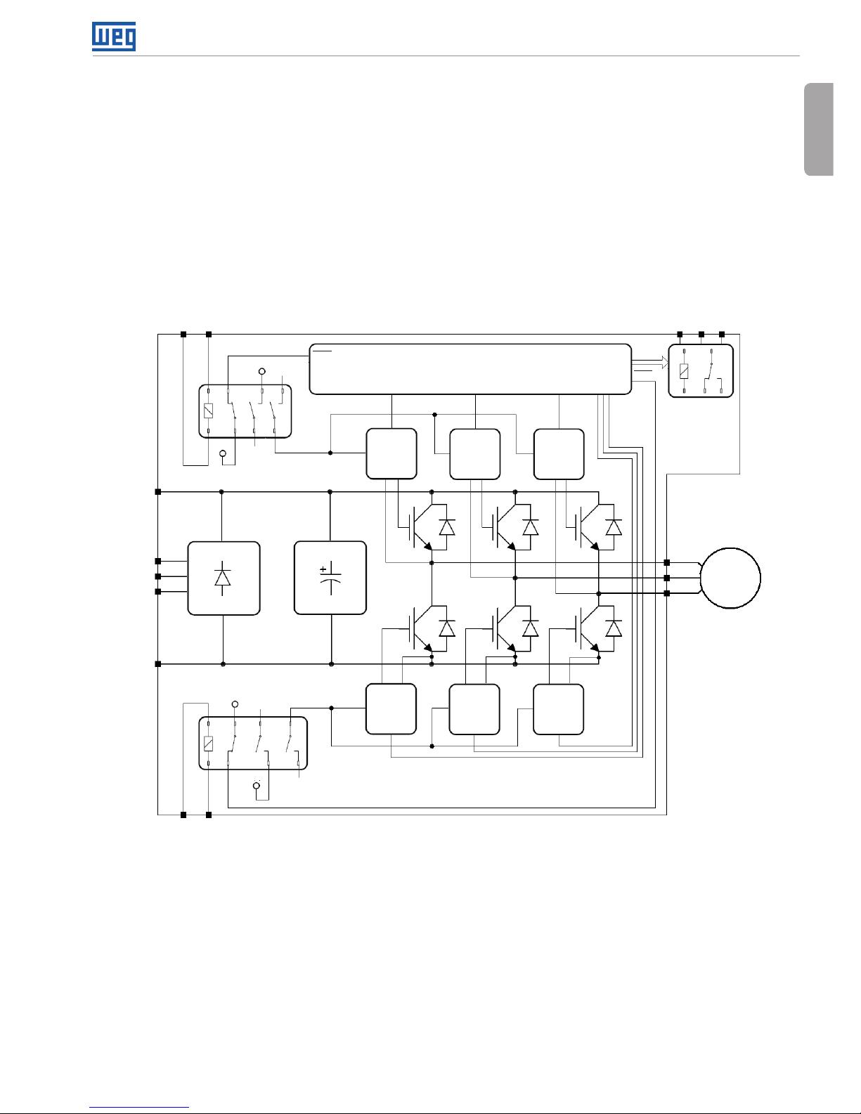
Those inverters have an additional board (SRBXX) with two safety relays (K1 and K2) that actuate
directly on the power circuit of the inverter (more specifically on the IGBT gate drivers power supply,
for further information see the figure 1) and guarantee that the IGBTs remain switched off while
safety stop function is activated, even in case of an internal single failure. The position of SRBXX
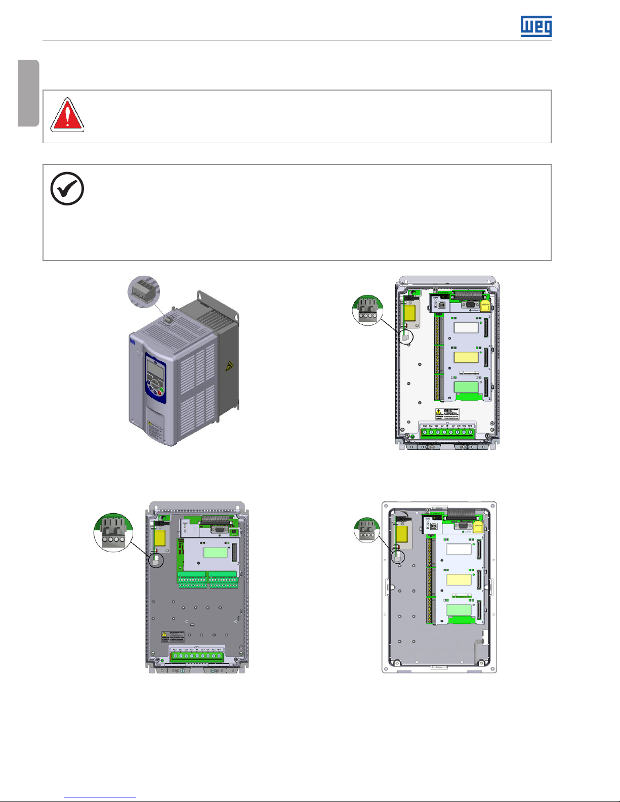
board and XC25 terminals (safety stop terminals) on the inverter is shown in figure 2.
Control Circuit (Microcontroller+EPLD)
Gate
Driver
Circuit
Gate
Driver
Circuit
XC25:1
XC25:3
2
V1
V1
S1
S1
K1
K2
S2
S2
+5V
+5V
4
PWM1
PWM3
PWM5
Rectifier
DC Link
Capacitors
Gate
Driver
Circuit
Gate
Driver
Circuit
Gate
Driver
Circuit
Gate
Driver
Circuit
Digital (Relay)
Outputs
XC1
X1
X1:
X1:
X1:
DC+
DC-
U/T1
R/L1
V/T2
S/L2
Motor
W/T3
T/L3
SR1
PWM6
PWM4
PWM2
SR2
Notes:
V1 = inverter internal voltage.
CFW-11M (more specifically power units) do not have R/L1, S/L2 and T/L3 terminals, They are fed by a DC voltage only,
SRBXX board is located on the control unit – in this case, K1 and K2 safety relays actuate on the fiber optic transceivers that
send PWM pulses to power units (UP11-XX) for firing the IGBTs.
Figure 1: Basic block diagram of safety stop function available in CFW-11, CFW-11M and CF W70x
inverter series
Page 6
Safety Stop Function
6 | CFW-11, CFW-11M, CFW70X
English
Safety stop function prevents the motor starting accidentally.
DANGER!
The activation of the safety stop function does not guarantee electrical safety of the motor
terminals they are not isolated from the power supply in this condition.
NOTE!
Inverter safety stop function is only one component of the safety control system of a
machine and/or process. When inverter and its safety stop function is correctly used
and with other safety components, it’s possible to fulfill the requirements of standard
EN 954-1 / ISO 13849-1, Category 3 (machine safety) and IEC/EN 61508, SIL2 (safety
control/signalling applied to processes and systems).
XC25
XC25
(a) CFW-11 and CFW70x frame A inverters –
SRB1A.00 board
(b) CFW-11 frame B and C inverters –
SRB2A.00 board
XC25
XC25
(c) CFW70x frame B and C inverters – SRB2A.00
board
(d) CFW-11 frame D and E inverters and
CFW-11M (UC11) inverters – SRB2A.00 board for
200...240 V / 220...230 V and 380...480 V models
and SRB4.00 for 500...690 V models
Figure 2: SRBXX board (safety stop function)
Page 7
Safety Stop Function
CFW-11, CFW-11M, CFW70X | 7
English
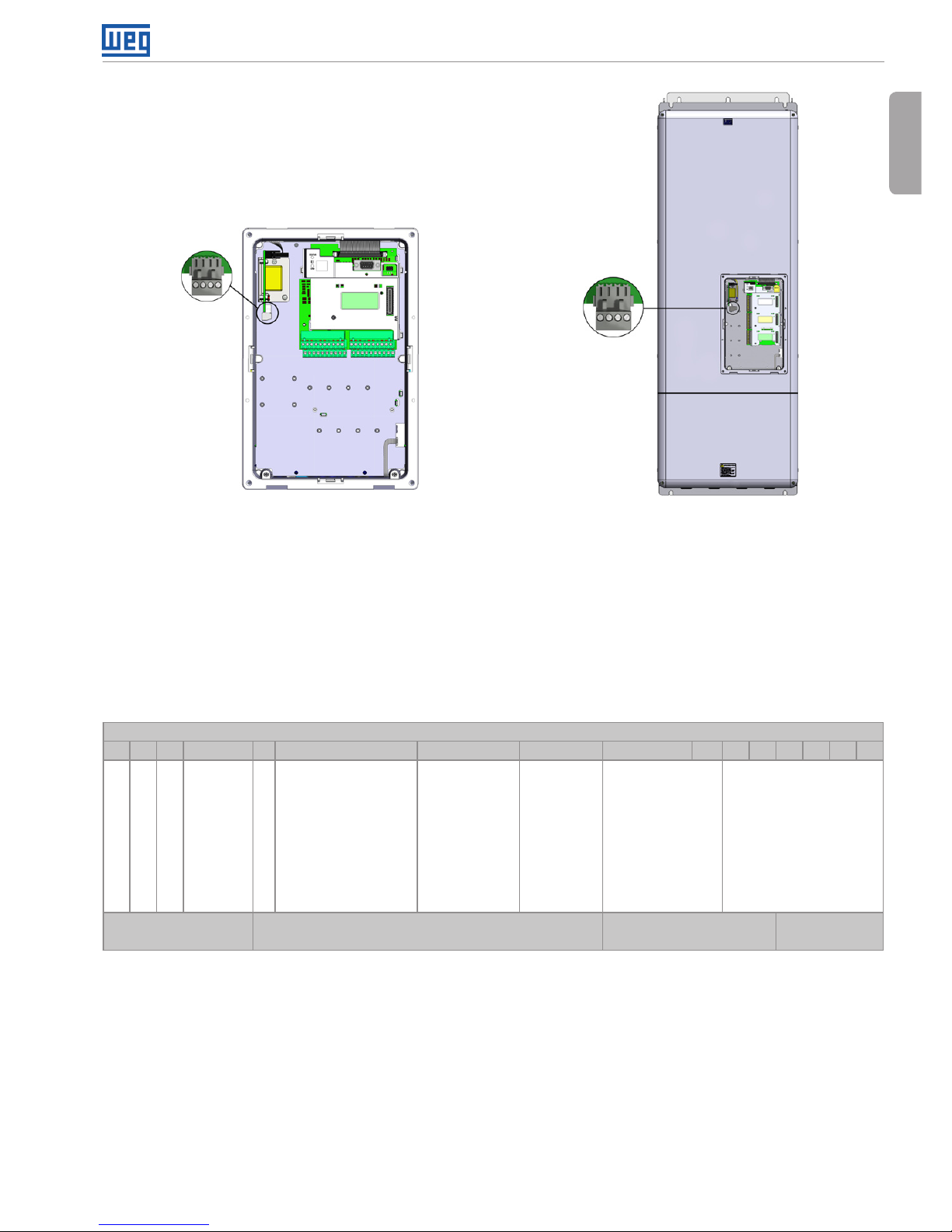
XC25
XC25
(e) CFW70x frame D and E inverters –
SRB2A.00 board for 200...240 V / 220...230 V and
380...480 V models and SRB4.00 for 500...600 V
models
(f) CFW-11 frame F and G inver ters –
SRB3.00 board
Figure 2 (cont.): SRBXX board (safety stop function)
Bit 9 of parameter P0029 content shows if the inverter have identified correctly SRBXX board.
Refer to table 1 for further information.
Table 1: Content of P0029 parameter
Bits
15 14 13 12 11 10 9 8 7 6 5 4 3 2 1 0
1 1 0 0 = With
braking
IGBT
1 =
Without
braking
IGBT.
0 0 = control circuit
is supplied from an
external +24 Vdc
power supply
1 = control circuit
is fed by the
inverter SMPS.
0 = Inverter
without
safety stop
option
1 = Inverter
with safety
stop option.
0 =
Inverter
without
RFI filter
1= Inverter
with RFI
filter.
Voltage rating of
the inverter:
00 = 200...240 V
/ or 220/230 V
01 = 380...480 V
10 = 500...600 V
11 = 500...690 V
or 660/690 V
Inverter output rated
current.
Hexadecimal
digit #4
Hexadecimal
digit #3
Hexadecimal
digit #2
Hexadecimal
digit #1
Page 8

Safety Stop Function
8 | CFW-11, CFW-11M, CFW70X
English
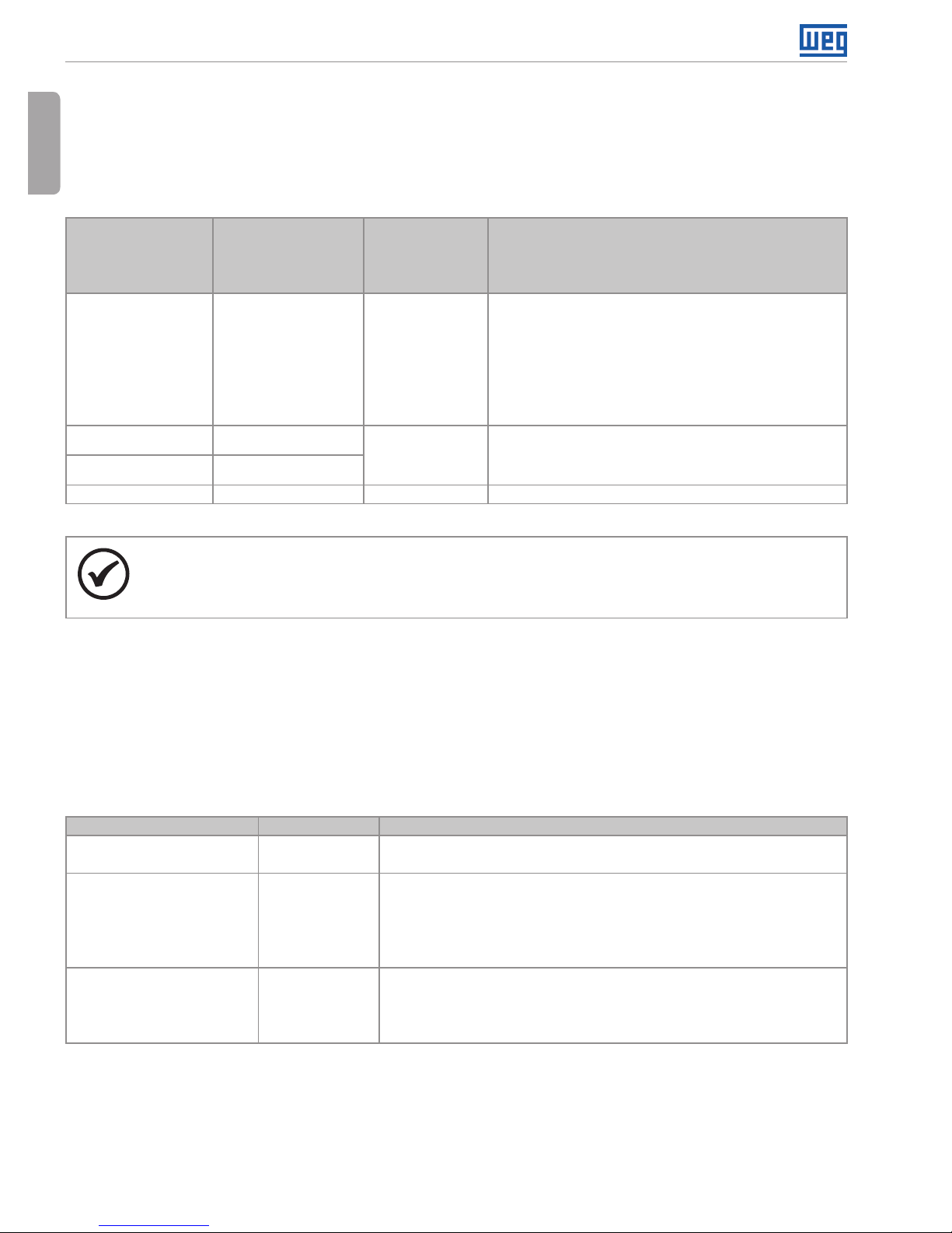
2. INSTALLATION
Table 2: XC25 terminals (safety stop terminals) signals
XC25 terminals Function Specifications
1 STO1
Terminal 1 of
safety relay K1 coil.
Coil rated voltage: 24 V, range: 20…30 Vdc
Coil resistance: 960 Ω ± 10 % @ 20 °C (68 °F).
2 GND1
Terminal 2 of
safety relay K1 coil.
3 STO2
Terminal 1 of
safety relay K2 coil.
Coil rated voltage: 24 V, range: 20…30 Vdc
Coil resistance: 960 Ω ± 10 % @ 20 °C (68 °F).
4 GND2
Terminal 2 of
safety relay K2 coil.
NOTE!
XC25:2 and XC25:4 terminals are not connected internally to inverter +24 V power supply
reference. In most of cases, those terminals are connected to XC1:11 control terminal in
CFW-11 and CFW-11M inverters and to XC1:36 in CFW70X inverters.
NOTE!
Follow the instructions provided on item 3.2.5 (CFW-11 and CFW70x) or 3.4.8
(CFW-11M) of User’s Manual.
For XC25 control cabling consider the following:
Use wire gauge from 0.5 mm
2
(20 AWG) to 1.5 mm2 (14 AWG) and maximum tightening torque
of maximum 0.50 N.m (4.50 lbf.in).
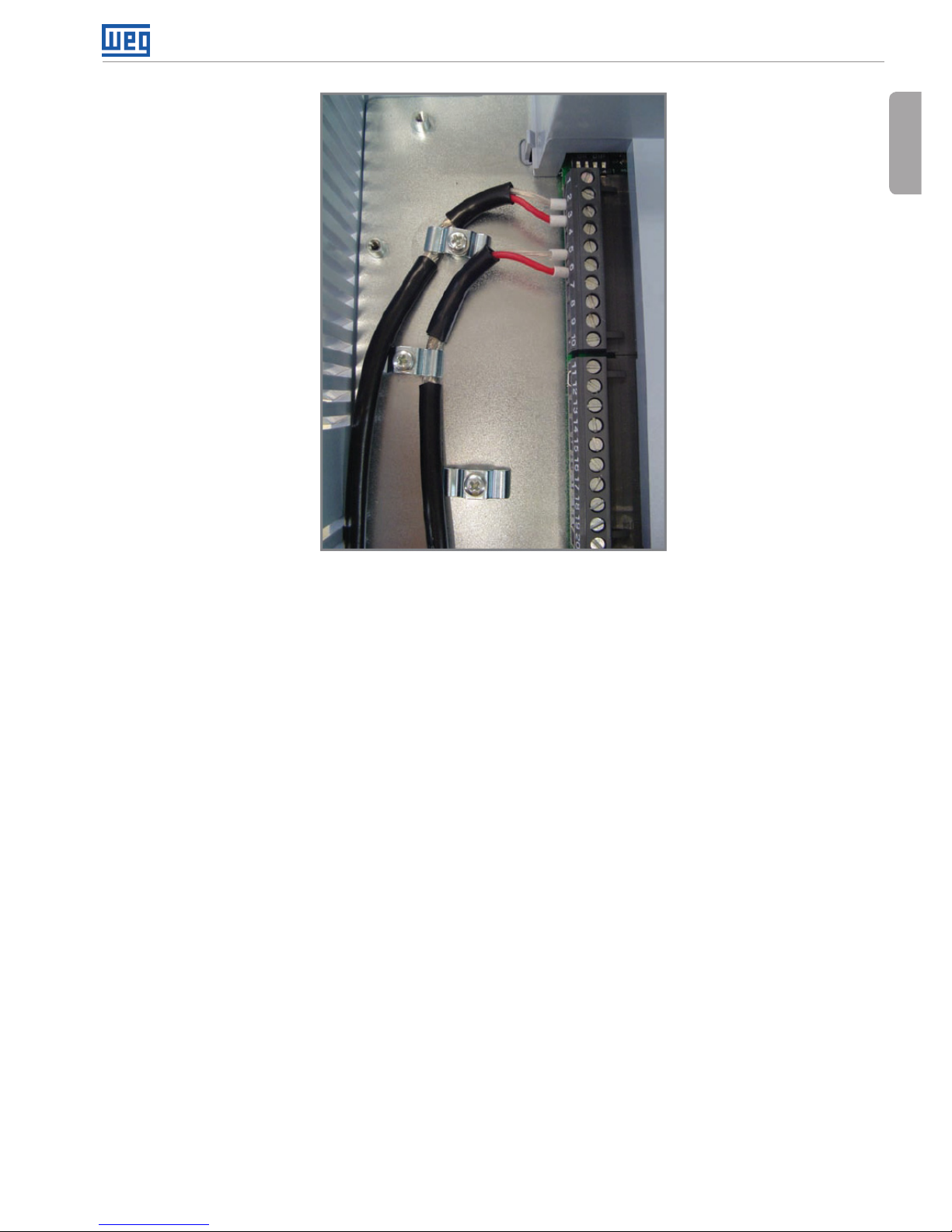
Use shielded cables connected to ground only on inverter side (use the provided metallic pieces
as shown on figure 3).
Run the cables separated from the remaining circuits (power, 110 V/220 Vac control, etc.).
Page 9
Safety Stop Function
CFW-11, CFW-11M, CFW70X | 9
English
Figure 3: Example of connection of shielding of control cable (in this case it was presented an example of
cables connected on XC1 terminals, but the same applies to XC25 terminals)
If the degree of protections of the used inverter is lower than IP54, it must be installed inside an
IP54 (minimum) cabinet.
Page 10
Safety Stop Function
10 | CFW-11, CFW-11M, CFW70X
English
3. OPERATION
3.1 TRUTH TABLE
Table 3: Safety stop function operation
STO1 logic level
(voltage between
XC25:1-3
terminals)
STO2 logic level
(voltage between
XC25:2-4
terminals)
Safety stop
function
Inverter behavior
0 (0 V) 0 (0 V)
Activated
(enabled)
Inverter remains in STO state and does not
accept commands. In CFW70x inverters with
software version V1.02 or higher, it’s indicated
A170 (activation of safety stop function advice)
on the keypad. In order to escape this condition,
it’s required to have STO1 = 1 and STO2 = 1
simultaneously.
0 (0 V) 1 (24 V)
Fault
Inverter is tripped by F160 fault (safety stop
function related fault). To escape this condition,
it’s required to reset the inverter.
1 (24 V) 0 (0 V)
1 (24 V) 1 (24 V) Disabled Inverter accepts commands normally.
NOTE!
Maximum delay between STO1 and STO2 signals: 100 ms (otherwise inverter will be
tripped by F160 fault).
Safety stop function takes priority over all other functions of the inverter.
This function should not be used as a control for starting and/or stopping the inverter.
3.2 STATE OF INVERTER, FAULT AND ALARM RELATED TO SAFETY STOP FUNCTION
Table 4: State of inverter, fault and alarm related to safety stop function
State / fault / alarm Description Cause
STO state Safety stop
activated
Voltage between terminals 1 and 3 (relay K1 coil) and between
terminals 2 and 4 (relay K2 coil) of XC25 higher than 17 V.
F160 fault Safety stop
function fault
It’s applied voltage to relay K1 coil (STO1) but it’s not applied
voltage to relay K2 coil (STO2) or vice-versa or there is a delay
of more than 100ms between one signal and the other. To solve
it, correct the external circuit that generates STO1 and STO2
signals.
A170 alarm (only on
CFW70x inverters with
software version V1.02
or higher)
Safety stop
activated
Only for keypad indication purpose, this alarm is indicated in
CFW70x inverters when the state of inverter is switched to STO.
Page 11
Safety Stop Function
CFW-11, CFW-11M, CFW70X | 11
English
3.3 STO STATUS INDICATION
State of the inverter is shown on the left upper side of the display of the keypad of CFW-11 and
CFW-11M series, on the mid upper region of keypad of CFW70x series (not all states of the inverter
are indicated on the keypad of CFW70x) and in parameter P0006.
Possible states of the inverter: ready, run (inverter enabled), undervoltage, fault, self-tunning,
configuration, DC braking and STO (safety stop function activated).
It’s possible to set one or more digital and relay outputs of the inverter to indicate that safety stop
function is activated (state of the inverter = STO), if the inverter is or not on a fault state and more
specifically if the inverter was tripped by F160 fault (safety stop function fault). For that set the
parameters P0275 (DO1), P0276 (DO2), P0277 (DO3), P0278 (DO4) and P0279 (DO5) according
to table 5.
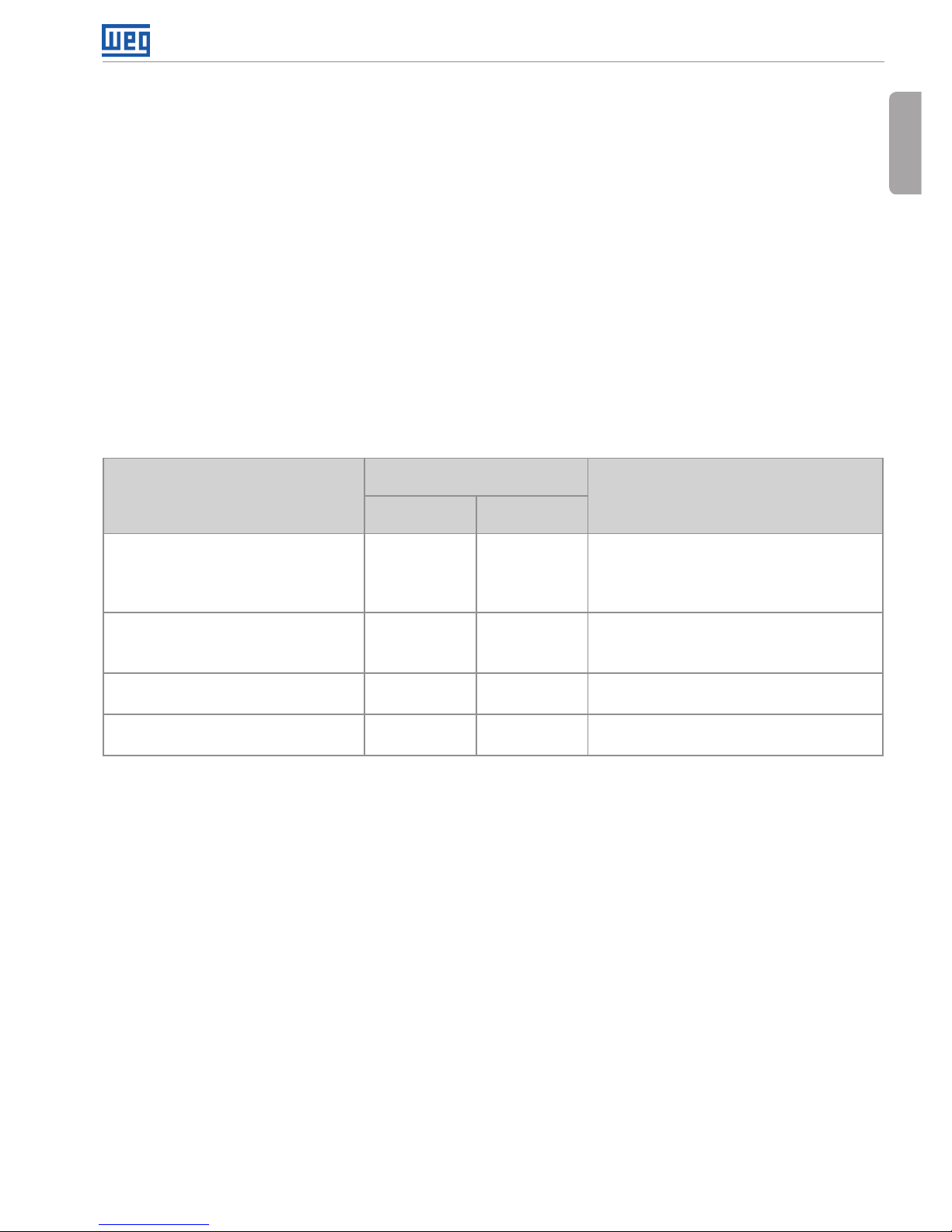
Table 5: P0275...P0279 options for indication of state of inverter or faults on DOx digital outputs
DOx digital output function
Value to be set
on P0275...P0279
Comment
CFW-11 and
CFW-11M
CFW70x
State of the inverter = STO
(safety stop function activated).
33 30 Safety stop function disabled:
relay/transistor OFF.
Safety stop function activated:
relay/transistor ON.
F160 fault
(inverter tripped by safety stop
function fault actuation).
34 31 Without F160 fault: relay/transistor OFF.
With fault F160: relay/transistor ON.
Fault (inverter tripped by
actuation of any fault).
13 13 Without fault: relay/transistor OFF.
With fault: relay/transistor ON.
Without fault
(state of the inverter is not fault).
26 24 With fault: relay/transistor OFF.
Without fault: relay/transistor ON.
Refer to CFW-11 inverter programming manual for a complete list of options for parameters
P0275...P0279.
3.4 PERIODIC TEST
Safety stop function, alternatively safety stop inputs (STO1 and STO2), must be activated at least
once a year for preventive maintenance purposes. Inverter power supply must be switched off
and then on again before carrying out this preventive maintenance. If during testing the power
supply to the motor is not switched off, safety integrity is no longer assured for the safety stop
function. The drive must therefore be replaced to ensure the operational safety of the machine or
of the system process.
Page 12

Safety Stop Function
12 | CFW-11, CFW-11M, CFW70X
English
4. EXAMPLES OF WIRING DIAGRAMS OF INVERTER CONTROL SIGNAL
It’s recommended to use inverter DI1 and DI2 digital inputs set as 3-wire start/stop commands
and the wiring diagrams of inverter control signal according to figure 4.
XC1:11 - DGND*
XC25:2 - GND(R1-)
XC25:1 - STO1(R1+)
XC25:3 - STO2(R2+)
XC25:4 - GND(R2-)
XC1:12 - COM
XC1:13 - +24V
XC1:15 - DI1
XC1:16 - DI2
Stop
Start
Emergency
Stop
CFW-11/
CFW-11M
XC1:36 - GND(24V)
XC25:2 - GND(R1-)
XC25:1 - STO1(R1+)
XC25:3 - STO2(R2+)
XC25:4 - GND(R2-)
XC1:35 - COM
XC1:34 - +24V
XC1:37 - DI1
XC1:38 - DI2
Stop
Start
Emergency
Stop
CFW70X
(a) STO or SS0 safety function with
CFW-11 and CFW-11M inverters
(b) STO or SS0 safety function with CFW70x
inverters
External
XC1:11 - DGND*
XC25:2 - GND(R1-)
XC25:1 - STO1(R1+)
XC25:3 - STO2(R2+)
XC25:4 - GND(R2-)
XC1:12 - COM
XC1:13 - +24V
XC1:15 - DI1
A1 A2
XC1:16 - DI2
Stop
Start
Safety Relay
CFW-11/
CFW-11M
14 24 48 58
13 23 47 57
(c) SS1 safety function with CFW-11 and CFW-11M inverters
(*)
External
XC1:36 - GND(24V)
XC25:2 - GND(R1-)
XC25:1 - STO1(R1+)
XC25:3 - STO2(R2+)
XC25:4 - GND(R2-)
XC1:35 - COM
XC1:34 - +24V
XC1:37 - DI1
XC1:38 - DI2
Stop
Start
Safety Relay
CFW70X
13 23 47 57
14 24 48 58
A1 A2
(d) SS1 safety function with CFW70x inver ters
(*)
(*) For specifications of external safety relay that is required to realize SS1 (stop category 1) refer to item 5.
Figure 4: Inverter control wiring examples (XC1 and XC25 terminals) to realize STO (or SS0, i.e., stop category 0)
and SS1 (stop category 1) safety functions according to IEC/EN 61800-5-2 and IEC/EN 60204-1 standards –
DI1 and DI2 inputs set as 3-wire start/stop commands
Page 13

Safety Stop Function
CFW-11, CFW-11M, CFW70X | 13
English
Circuit operation of SS1 function (figures 4c and 4d):
In this case, when the activation command is given to the external safety relay, safety relay
opens inverter DI2 signal (via terminals 23 to 24) and motor is decelerated first by the inverter (via
deceleration ramp). When the time delay set at the external safety relay expires (this delay must
be higher than required time to stop the motor, taking into account deceleration time set on the
inverter and inertia of the motor load), the safety relay delayed contacts (terminals 47 to 48 and
57 to 58) opens inverter STO1 and STO2 signals and the inverter safety stop function is activated.
The motor stops according to category 1 (SS1) of standard IEC/EN 60204-1. In order to drive the
motor again, it’s required to apply STO1 and STO2 signals again (to close terminals 13 to 23 and
23 to 24) and to have a pulse on inverter DI1 input (to apply a pulse on START switch).
5. TECHNICAL SPECIFICATIONS
5.1 ELECTRICAL CONTROL CHARACTERISTICS
Safety stop function inputs XC25:1-2, XC25:3-4 2 independent inputs for safety stop function.
Power supply: 24 Vdc (max. 30 V)
Impedance: 960 Ω
State 0 if < 2 V, state 1 if > 17 V
External
safety relay specifications
(only when SS1 function is
required according to IEC/
EN 61800-5-2 and IEC/EN
60204-1 standards – refer
to figures 4c/4d).
General requirements IEC 61508 and/or EN 954-1 and/or ISO 13849-1
Output requirements No. of current paths: 2 independent paths (one for
each STO path)
Switching voltage capability: 30 Vdc per contact
Switching current capability: 100 mA per contact
Maximum switching delay between contacts: 100 ms.
Example Type/manufacturer: WEG / Instrutech CPt-D.
5.2 OPERATIONAL SAFETY CHARACTERISTICS
Protection Of the machine Safety stop function which forces stopping and/or
prevents the motor from restarting unintentionally,
conforming to EN 954-1 / ISO 13849-1 category 3,
IEC/EN 61800-5-2 and IEC/EN 60204-1.
Of the system process Safety stop function which forces stopping and/or
prevents the motor from restarting unintentionally,
conforming to IEC/EN 61508 level SIL2 and
IEC/EN 61800-5-2.
NOTE!
Certification of the product is in annex.
Page 14

Función Parada Segura
14 | CFW-11, CFW-11M, CFW70X
Español
1. INFORMACIONES GENERALES
Los convertidores de frecuencia con la opción parada de seguridad poseen en su nomenclatura
el sufijo Y (CFW-11 y CFW-11M) o el sufijo Y1 (CFW70x). La unidad de control del CFW-11M con
el accesorio opcional parada de seguridad también posee el sufijo Y en su nombre (ejemplo:
UC11-1340T5OYZ).
Estos convertidores poseen una tarjeta adicional (SRBXX) con dos relés de seguridad (K1 y K2) que
actúan directamente en el circuito de potencia del convertidor de frecuencia (más específicamente
en la alimentación de los “Gate Drivers” del IGBT; para mayores detalles consultar la figura 1) y se
garantiza que los IGBTs permanezcan deshabilitado cuando la función parada de seguridad se
encuentra activa, mismo que ocurra un fallo o defecto interno. La posición de la tarjeta SRBXX y
de los terminales XC25 (conector de la parada de seguridad) en el convertidor de frecuencia es
presentada en la figura 2.
Circuito
del Gate
Driver
Circuito
del Gate
Driver
XC25:1
XC25:3
2
V1
V1
S1
S1
K1
K2
S2
S2
+5V
+5V
4
Rectificador
Condensadores
del link CC
Circuito
del Gate
Driver
Circuito
del Gate
Driver
Circuito
del Gate
Driver
Circuito
del Gate
Driver
Salidas
digitales
a rele
XC1
X1
X1:
X1:
X1:
DC+
DC-
U/T1
R/L1
V/T2
S/L2
Motor
W/T3
T/L3
SR1
SR2
Circuito del control (Microcontrolador + EPLD)
PWM1
PWM3
PWM5
PWM6
PWM4
PWM2
¡Notas!
V1 = tensión interna del convertidor de frecuencia.
Los modelos CFW-11M (más específicamente las unidades de potencia) no poseen los terminales R/L1, S/L2 y T/L3, Son
alimentados solamente con tensión CC, la tarjeta SRBXX se queda en la unidad de control – en ese caso, los relés de
seguridad K1 y K2 actúan en los transmisores de fibra óptica que envían los pulsos PWM para los disparos de los IGBTs
hasta las unidades de potencia (UP11-XX).
Figura 1: Diagrama de bloques básico de la función parada de seguridad de los convertidores
CFW-11, CFW-11M y CFW70x
Page 15

Función Parada Segura
CFW-11, CFW-11M, CFW70X | 15
Español
La función parada de seguridad evita que el motor sea accidentalmente accionado.
¡PELIGRO!
La activación de la función parada de seguridad no garantiza la seguridad eléctrica de los
terminales del motor. Estos, no se quedan aislados de la red eléctrica en esta condición.
¡NOTA!
La función parada de seguridad del convertidor de frecuencia es solamente una parte del
sistema de seguridad de una máquina y/o proceso. Cuando el convertidor de frecuencia
y esa función son correctamente utilizados y en conjunto con otros componentes de
seguridad, es posible cumplir con la normativa EN 954-1 / ISO 13849-1, Categoría 3.
XC25
XC25
(a) Convertidores de Frecuencia CFW-11 y CFW70x
talla A – tarjeta SRB1A.00
(b) Convertidor de Frecuencia CFW-11 talla B y C –
tarjeta SRB2A.00
XC25
XC25
(c) Convertidores de Frecuencia CFW70x talla
B y C – tarjeta SRB2A.00
(d) Convertidores de Frecuencia CFW-11 tamaño
D y E CFW11M (UC11) - tarjeta SRB2A.00 para
modelos 200...240 V / 220...230 V y 380...480 V y
tarjetas SRB4.00 para modelos 500...690 V
Figura 2: Tarjeta SRBXX (función de seguridad de parada)
Page 16

Función Parada Segura
16 | CFW-11, CFW-11M, CFW70X
Español
XC25
XC25
(e) Convertidores de Frecuencia CFW70x
tamaño D y E - tarjeta SRB2A.00 para
modelos 200...240 V / 220...230 V y 380...480
V y tarjetas SRB4.00 para modelos 500...600 V
(f) Convertidores de Frecuencia CFW-11 talla
F y G – tarjeta SRB3.00
Figura 2 (cont.): Tarjeta SRBX X (función de seguridad de parada)
El bit 9 del contenido del parámetro P0029 señaliza si el convertidor de frecuencia identificó
correctamente la tarjeta SRBXX. Para mayores detalles consultar la tabla 1.
Tabla 1: Contenido del parámetro P0029
Bits
15 14 13 12 11 10 9 8 7 6 5 4 3 2 1 0
1 1 0 0 = Con
IGBT de
frenado
1 = Sin
IGBT de
frenado.
0 0 = Alimentación
independiente del
circuito de control
vía fuente 24 Vcc
1 = Control
alimentado
vía tarjeta de
potencia.
0 =
Convertidor
de
frecuencia
sin la tarjeta
opcional
parada de
seguridad
1 =
Convertidor
de
Frecuencia
con la
tarjeta
opcional
parada de
seguridad.
0 =
Convertidor
de
frecuencia
sin filtro RFI
1=
Convertidor
de
frecuencia
con filtro
RFI.
Rango de
tensión del
convertidor de
frecuencia:
00 = 200...240 V
o 220/230 V
01 = 380...480 V
10 = 500...600 V
11 = 500...690 V
o 660/690 V
Corriente nominal
del convertidor de
frecuencia.
Dígito
hexadecimal #4
Dígito
hexadecimal #3
Dígito
hexadecimal #2
Dígito
hexadecimal #1
Page 17

Función Parada Segura
CFW-11, CFW-11M, CFW70X | 17
Español
2. INSTALACIÓN
Tabla 2: Señales en los bornes XC25 (conector de la parada de seguridad)
Bornes XC25 Función Especificaciones
1 STO1
Terminal 1 de la
bobina del relé K1.
Tensión nominal de la bobina: 24 V,
rango de 20 a 30 Vcc
Resistencia de la bobina: 960 Ω ± 10 % @ 20 °C
2 GND1
Terminal 2 de la
bobina del relé K1.
3 STO2
Terminal 1 de la
bobina del relé K2.
Tensión nominal de la bobina: 24 V,
rango de 20 a 30 Vcc
Resistencia de la bobina: 960 Ω ± 10 % @ 20 °C
4 GND2
Terminal 2 de la
bobina del relé K2.
¡NOTA!
Los terminales XC25:2 y XC25:4 no están interconectados internamente a la referencia
de la fuente +24 V del convertidor de frecuencia. En la mayoría de las veces se conecta
estos terminales al terminal de controle XC1:11 en los inversores CFW-11 y CFW-11M y
al XC1:36 para el inversor CFW70X.
¡NOTA!
Seguir las recomendaciones del ítem 3.2.5 (CFW-11 y CFW70x) o 3.4.8 (CFW-11M) del
manual del usuario.
Consideraciones para el cableado en XC25:
Utilizar calibre de los cables en el rango de 0.5 mm
2
(20 AWG) a 1.5 mm2 (14 AWG) y par (torque)
de aprieto máximo de 0.5 N.m (4.50 lbf.in).
Utilizar cable blindado puestos a tierra solamente del lado del convertidor de frecuencia (utilizar
piezas metálicas de puesta a tierra de los cables de control conforme presentado en la figura 3).
Separar de los demás cableados (potencia, mando en 110 V/220 Vca, etc).
Page 18

Función Parada Segura
18 | CFW-11, CFW-11M, CFW70X
Español
Figura 3: Ejemplo de conexión del blindaje de los cables de control (en ese caso fue presentado el ejemplo de
cables conectados en XC1, más el mismo se aplica a los cables conectados en XC25)
Si el grado de protección del inversor utilizado es inferior a IP54, debe ser instalado dentro de un
armario IP54 (mínimo).
Page 19

Función Parada Segura
CFW-11, CFW-11M, CFW70X | 19
Español
3. PUESTA EN MARCHA
3.1 TABLA-VERDAD
Tabla 3: Funcionamiento de la función parada de seguridad
STO1 nivel lógico
(tensión entre
XC25:1-3)
STO2 nivel lógico
(tensión entre
XC25:2-4)
Función parada
de seguridad
Comportamiento del Convertidor de
Frecuencia
0 (0 V) 0 (0 V) Activa
Convertidor de frecuencia se queda en estado
STO y no acepta comandos. En el caso del
CFW70x con versión de software V1.02 o
superior, también es indicado A170 (aviso de
actuación de la función parada de seguridad) en
la HMI. Para salir de esa condición, basta hacer
STO1 = 1 y STO2 = 1 simultáneamente.
0 (0 V) 1 (24 V)
Fallo
Convertidor de frecuencia es bloqueado por
F160 (falla relacionada a la función parada de
seguridad). Para salir de esa condición, es
necesario resetear el convertidor de frecuencia.
1 (24 V) 0 (0 V)
1 (24 V) 1 (24 V) Inactiva
Convertidor de frecuencia acepta mandos
normalmente.
¡NOTA!
Retraso máximo entre señales STO1 y STO2: 100 ms (caso contrario el convertidor de
frecuencia será bloqueado por F160).
La función parada de seguridad es prioritaria sobre todas las otras funciones del convertidor de
frecuencia.
Esa función no debe ser usada para controlar el arranque y/o parada del convertidor de frecuencia.
3.2 ESTADO DEL CONVERTIDOR DE FRECUENCIA, FALLOS Y ALARMAS RELACIONADOS
A LA FUNCIÓN DE PARADA DE SEGURIDAD
Tabla 4: Estado del convertidor de frecuencia, fallos y alarmas relacionados a la función de parada de seguridad
Estado / fallo / alarma Descripción Causa
Estado STO Función parada
de seguridad
activa.
Tensión entre los terminales 1 y 3 (bobina del relé K1) y entre los
terminales 2 y 4 (bobina del relé K2) de XC25 mayor que 17V.
Fallo F160 Fallo de la
función de
parada de
seguridad.
Se aplicada tensión en la bobina del relé K1 (STO1) más no se
aplicada tensión en la bobina del relé K2 (STO2) o viceversa o
existe una diferencia de más de 100 ms entre el accionamiento
de un relé y del otro. Para solucionar eso, arreglar las lógica
externa que genera las señales STO1 y STO2.
Alarma A170
(solamente en los
convertidor de frecuencia
CFW70x con versión de
software V1.02 o superior).
Función parada
de seguridad
activa.
Para fines de señalización en la HMI, esa alarma es presentada
en el CFW70x cuando el estado del convertidor de frecuencia
es igual a STO.
Page 20

Función Parada Segura
20 | CFW-11, CFW-11M, CFW70X
Español
3.3 SEÑALIZACIÓN DEL ESTADO DE LA FUNCIÓN “SAFETY STOP”
El estado del convertidor de frecuencia es presentado en el canto izquierdo superior del display de la
HMI del CFW-11 y CFW-11M, en el área central superior de la HMI del CFW70x (ni todos los estados
del convertidor de frecuencia son señalados en la HMI del CFW70x) y en el parámetro P0006.
Estados posibles: ready (listo), run (convertidor de frecuencia habilitado), subtensión, fallo,
autoajuste, configuración, frenado CC y STO (función parada de seguridad activa).
Es posible programar una o más salidas a relé y digitales del convertidor de frecuencia para
señalizar que la función parada de seguridad está activa (estado del convertidor de frecuencia
= STO), si el convertidor de frecuencia está o no en estado de fallo y más específicamente si el
convertidor de frecuencia fue bloqueado por F160 (fallo de la función parada de seguridad). Eso
es hecho ajustándose el contenido de los parámetros P0275 (DO1), P0276 (DO2), P0277 (DO3),
P0278 (DO4) y P0279 (DO5) de acuerdo con la tabla 5.
Tabla 5: Opciones de P0275...P0279 para señalización del estado y fallos del convertidor de frecuencia en las
salidas digitales DOx
Función de la salida digital DOx
Valor a ser ajustado en
P0275...P0279
Comentario
CFW-11 y
CFW-11M
CFW70x
Estado del convertidor de
frecuencia = STO (función parada
de seguridad activa).
33 30 Función parada de seguridad inactiva:
relé/transistor OFF.
Función parada de seguridad activa:
relé/transistor ON.
Fallo F160 (convertidor de
frecuencia bloqueado por la
actuación del fallo de la función de
parada de seguridad).
34 31 Sin fallo F160: relé/transistor OFF.
Con fallo F160: relé/transistor ON.
Fallo (convertidor de frecuencia
fue bloqueado por la actuación de
cualquier fallo).
13 13 Sin fallo: relé/transistor OFF.
Con fallo: relé/transistor ON.
Sin fallo (ninguno fallo del
convertidor de frecuencia fue
activada).
26 24 Con fallo: relé/transistor OFF.
Sin fallo: relé/transistor ON.
Para una lista completa de opciones de los parámetros P0275...P0279 consultar el manual de
programación del convertidor de frecuencia CFW-11.
3.4 TESTE PERIÓDICO
La función Parada de Seguridad debe ser activada por lo menos una vez al año con el objetivo
de mantenimiento preventivo. Este procedimiento es realizado a través de las entradas STO1 y
STO2 conforme es presentado en la tabla 3. La alimentación del convertidor debe ser retirada y
entonces conectada nuevamente, antes de ejecutar el mantenimiento preventivo. La función Parada
de Seguridad estará funcionando correctamente si durante el test es interrumpida la alimentación
del motor (el motor debe parar) y no ocurre la actuación de fallas en el convertidor. En caso de que
el convertidor no pase en ese test, es necesario sustituirlo para garantizar la seguridad operacional
de la máquina o del proceso en cuestión.
Page 21

Función Parada Segura
CFW-11, CFW-11M, CFW70X | 21
Español
4. EJEMPLOS DE DIAGRAMAS DE CONEXIÓN DE LAS SEÑALES DE CONTROL
DEL CONVERTIDOR
Se sugiere utilizar las entradas digitales DI1 y DI2 del convertidor de frecuencia programadas
como mandos “start” y “stop” 3 cables y el diagrama de conexiones de las señales de control del
convertidor de frecuencia conforme la figura 4.
XC1:11 - DGND*
XC25:2 - GND(R1-)
XC25:1 - STO1(R1+)
XC25:3 - STO2(R2+)
XC25:4 - GND(R2-)
XC1:12 - COM
XC1:13 - +24V
XC1:15 - DI1
XC1:16 - DI2
Stop
Start
Emergency
Stop
CFW-11/
CFW-11M
XC1:36 - GND(24V)
XC25:2 - GND(R1-)
XC25:1 - STO1(R1+)
XC25:3 - STO2(R2+)
XC25:4 - GND(R2-)
XC1:35 - COM
XC1:34 - +24V
XC1:37 - DI1
XC1:38 - DI2
Stop
Start
Emergency
Stop
CFW70X
(a) Parada tipo STO o SS0 para los convertidores
de frecuencia CFW-11 y CFW-11M
(b) Parada tipo STO o SS0 para los convertidores
de frecuencia CFW70x
External
XC1:11 - DGND*
XC25:2 - GND(R1-)
XC25:1 - STO1(R1+)
XC25:3 - STO2(R2+)
XC25:4 - GND(R2-)
XC1:12 - COM
XC1:13 - +24V
XC1:15 - DI1
A1 A2
XC1:16 - DI2
Stop
Start
Safety Relay
CFW-11/
CFW-11M
14 24 48 58
13 23 47 57
(c) Parada tipo SS1 con Convertidor de Frecuencia CFW-11 y CFW-11M (*)
External
XC1:36 - GND(24V)
XC25:2 - GND(R1-)
XC25:1 - STO1(R1+)
XC25:3 - STO2(R2+)
XC25:4 - GND(R2-)
XC1:35 - COM
XC1:34 - +24V
XC1:37 - DI1
XC1:38 - DI2
Stop
Start
Safety Relay
CFW70X
13 23 47 57
14 24 48 58
A1 A2
(d) Parada tipo SS1 con Convertidor de Frecuencia CFW70x (*)
¡Nota! (*) Para especificar el relé de seguridad externo es necesario para implementar la parada tipo SS1 consultar el ítem 5.
Figure 4: Ejemplos de conexiones de las señales de control del convertidor de frecuencia (bornes XC1 y
XC25) para implementar las funciones de parada de seguridad tipo STO (o SS0, i.e., categoría de parada 0) y
SS1 (categoría de parada 1) conforme las normativas IEC/EN 61800-5-2 y IEC/EN 60204-1 respectivamente –
entradas DI1 y DI2 programadas como mandos start/stop 3 cables
Page 22

Función Parada Segura
22 | CFW-11, CFW-11M, CFW70X
Español
Operación del circuito de la parada tipo SS1 (figuras 4c y 4d):
En ese caso, cuando un mando de activación es enviado al relé de seguridad externo, el relé abre la
señal de la entrada DI2 del convertidor de frecuencia (vía terminales 23-24) y el motor es inicialmente
desacelerado por el convertidor de frecuencia (vía rampa de desaceleración). Cuando el intervalo
de tempo ajustado en el relé de seguridad se cumple (ese intervalo debe ser mayor que el tiempo
necesario para parar el motor, considerando la rampa de desaceleración ajusta y la inercia del
motor), los contactos de retraso del relé de seguridad (terminales 47-48 y 57-58) abren las señales
STO1 y STO2 y la función parada de seguridad del convertidor de frecuencia es activada. El motor
para de acuerdo con la categoría 1 (SS1) de la normativa IEC/EN 60204-1. Para accionar el motor
nuevamente, es necesario aplicar señales en STO1 y STO2 (cerrar los terminales 13-14 y 23-24) y
tener un pulso en la entrada DI1 del convertidor de frecuencia (aplicar un pulso en la llave START).
5. ESPECIFICACIONES TÉCNICAS
5.1 CARACTERÍSTICAS ELÉCTRICAS DE CONTROL
Entradas de la función
parada de seguridad.
XC25:1-2, XC25:3-4. 2 entradas independientes para función parada de
seguridad.
Alimentación: 24 Vcc (máx. 30 V)
Impedancia: 960 Ω
Nivel 0 si < 2 V, nivel 1 si > 17 V
Especificaciones del relé
de seguridad externo
(solamente cuando es
necesario la función SS1
conforme las normativas
IEC/EN 61800-5-2 y IEC/
EN 60204-1 – ver figuras
4c/4d).
Generales. IEC 61508 y/o EN 954-1 y/o ISO 13849-1
Especificaciones de salida. Número de circuito de corriente: 2 circuitos
independientes (una para STO1 y otro para STO2).
Capacidad de conmutación de tensión: 30 Vcc por
contacto.
Capacidad de conmutación de corriente: 100 mA
por contacto.
Máximo retraso entre los contactos: 100 ms.
Ejemplo. Tipo/fabricante: WEG / Instrutech CPt-D
5.2 CARACTERÍSTICAS DE SEGURIDAD OPERACIONAL
Protección. De la máquina. Función parada de seguridad que garantiza la parada
y/o evita el accionamiento no deseado del motor
conforme la normativa EN 954-1 / ISO 13849-1
categoría 3, IEC/EN 61800-5-2 y IEC/EN 60204-1.
Del sistema del proceso. Función parada de seguridad que garantiza la
parada y/o evita el accionamiento no deseado del
motor conforme la normativa IEC/EN 61508 nivel
SIL2 y IEC/EN 61800-5-2.
¡NOTA!
Certificación del producto es encontrada en el anexo.
Page 23

Função de Parada de Segurança
CFW-11, CFW-11M, CFW70X | 23
Português
1. INFORMAÇÕES GERAIS
Os inversores com a opção parada de segurança possuem na sua nomenclatura o sufixo Y
(inversores CFW-11 e CFW-11M) ou o sufixo Y1 (inversores CFW70x). A unidade de controle do
CFW-11M com o opcional parada de segurança também possui o sufixo Y no seu nome
(ex: UC11-1340T5OYZ).
Esses inversores têm um cartão adicional (SRBXX) com dois relés de segurança (K1 e K2) que
atuam diretamente no circuito de potência do inversor (mais especificamente na alimentação dos
gate drivers do IGBT, para maiores detalhes veja a figura 1) e garantem que os IGBTs permaneçam
desligados quando a função parada de segurança estiver ativa, mesmo que ocorra uma falha ou
defeito interno. A posição do cartão SRBXX e dos bornes XC25 (conector da parada de segurança)
no inversor é apresentada na figura 2.
Circuito
de Gate
Driver
Circuito
de Gate
Driver
XC25:1
XC25:3
2
V1
V1
S1
S1
K1
K2
S2
S2
+5V
+5V
4
Retificador
Capacitores
do Link CC
Circuito
de Gate
Driver
Circuito
de Gate
Driver
Circuito
de Gate
Driver
Circuito
de Gate
Driver
Saídas
Digitais a
Relé
XC1
X1
X1:
X1:
X1:
DC+
DC-
U/T1
R/L1
V/T2
S/L2
Motor
W/T3
T/L3
SR1
SR2
Circuito de Controle (Microcontrolador + EPLD)
PWM1
PWM3
PWM5
PWM6
PWM4
PWM2
Notas:
V1 = tensão interna do inversor.
Os modelos CFW-11M (mais especificamente as unidades de potência) não têm os terminais R/L1, S/L2 e T/L3, São
alimentados somente com tensão CC, o cartão SRBXX fica na unidade de controle – nesse caso, os relés de segurança
K1 e K2 atuam nos transmissores de fibra óptica que enviam os pulsos PWM para disparo dos IGBTs até as unidades de
potência (UP11-XX).
Figura 1: Diagrama de blocos básico da função parada de segurança dos inversores
CFW-11, CFW-11M e CFW70x
Page 24

Função de Parada de Segurança
24 | CFW-11, CFW-11M, CFW70X
Português
A função parada de segurança evita que o motor seja acidentalmente acionado.
PERIGO!
A ativação da função parada de segurança não garante segurança elétrica dos terminais
do motor. Estes, não estão isolados da rede elétrica nesta condição.
NOTA!
A função parada de segurança do inversor é somente uma parte do sistema de
segurança de uma máquina e/ou processo. Quando o inversor e essa função forem
corretamente utilizados e em conjunto com outros componentes de segurança, é
possível o atendimento da norma EN 954-1 / ISO 13849-1, Categoria 3.
XC25
XC25
(a) Inversores CFW-11 e CFW70x mecânica A –
car tão SRB1A.00
(b) Inversores CFW-11 mecânicas B e C –
car tão SRB2A.00
XC25
XC25
(c) Inversores CFW70x mecânicas B e C –
car tão SRB2A.00
(d) Inversores CFW-11 mecânicas D e E e
inversores CFW-11M (UC11) – cartão SRB2A.00
para modelos 200...240 V / 220...230 V e 380...480 V
e car tão SRB4.00 para modelos 500...690 V
Figura 2: Cartão SRBXX (função de parada de segurança)
Page 25

Função de Parada de Segurança
CFW-11, CFW-11M, CFW70X | 25
Português
XC25
XC25
(e) Inversores CFW70x mecânicas D e E –
car tão SRB2A.00 para modelos 200...240 V
/ 220...230 V e 380...480 V e cartão SRB4.00
para modelos 500...600 V
(f) Inversores CFW-11 mecânicas F e G –
car tão SRB3.00
Figura 2 (cont.): Cartão SRBXX (função de parada de segurança)
O bit 9 do conteúdo do parâmetro P0029 indica se o inversor identificou corretamente o cartão
SRBXX. Para maiores detalhes ver tabela 1.
Tabela 1: Conteúdo do parâmetro P0029
Bits
15 14 13 12 11 10 9 8 7 6 5 4 3 2 1 0
1 1 0 0 = Com
IGBT de
frenagem
1 = Sem
IGBT de
frenagem.
0 0 = Alimentação
independente
do circuito de
controle via fonte
24 Vcc
1 = Controle
alimentado
via cartão de
potência.
0 = Inversor
sem
opcional
parada de
segurança
1 = Inversor
com
opcional
parada de
segurança.
0 = Inversor
sem filtro
RFI
1= Inversor
com filtro
RFI.
Range de
tensão do
inversor:
00 = 200...240 V
ou 220/230 V
01 = 380...480 V
10 = 500...600 V
11 = 500...690 V
ou 660/690 V
Corrente nominal do
inversor.
Dígito
hexadecimal #4
Dígito
hexadecimal #3
Dígito
hexadecimal #2
Dígito
hexadecimal #1
Page 26

Função de Parada de Segurança
26 | CFW-11, CFW-11M, CFW70X
Português
2. INSTALAÇÃO
Tabela 2: Sinais nos bornes XC25 (conector da parada de segurança)
Bornes XC25 Função Especificações
1 STO1 Terminal 1 da bobina do relé K1.
Tensão nominal da bobina: 24 V, faixa de 20 a 30 Vcc
Resistência da bobina: 960 Ω ± 10 % @ 20 °C
2 GND1 Terminal 2 da bobina do relé K1.
3 STO2 Terminal 1 da bobina do relé K2.
Tensão nominal da bobina: 24 V, faixa de 20 a 30 Vcc
Resistência da bobina: 960 Ω ± 10 % @ 20 °C
4 GND2 Terminal 2 da bobina do relé K2.
NOTA!
Os terminais XC25:2 e XC25:4 não estão ligados internamente à referência da fonte +24 V
do inversor. Na maioria das vezes conecta-se estes terminais ao terminal de controle
XC1:11 nos inversores CFW-11 e CFW-11M e ao XC1:36 para o inversor CFW70X.
NOTA!
Seguir recomendações do item 3.2.5 (CFW-11 e CFW70x) ou 3.4.8 (CFW-11M) do
manual do usuário.
Considerações para fiação em XC25:
Utilizar bitola dos cabos na faixa de 0.5 mm
2
(20 AWG) a 1.5 mm2 (14 AWG) e torque de aperto
de no máximo 0.5 N.m (4.50 lbf.in).
Utilizar cabo blindado aterrado somente do lado do inversor (utilizar peças metálicas de
aterramento dos cabos de controle conforme apresentado na figura 3).
Separar das demais fiações (potência, comando em 110 V/220 Vca, etc).
Page 27

Função de Parada de Segurança
CFW-11, CFW-11M, CFW70X | 27
Português
Figura 3: Exemplo de conexão da blindagem dos cabos de controle (nesse caso foi apresentado exemplo de
cabos ligados em XC1, mas o mesmo se aplica aos cabos ligados em XC25)
Page 28

Função de Parada de Segurança
28 | CFW-11, CFW-11M, CFW70X
Português
3. COLOCANDO EM FUNCIONAMENTO
3.1 TABELA-VERDADE
Tabela 3: Funcionamento da função parada de segurança
STO1
(tensão entre
XC25:1-3)
STO2
(tensão entre
XC25:2-4)
Função parada
de segurança
Comportamento do inversor
0 0 Ativa.
Inversor fica em estado STO e não aceita
comandos. No caso do CFW70x com versão
de software V1.02 ou superior, também é
indicado A170 (aviso de atuação da função
parada de segurança) na HMI. Para sair dessa
condição, basta fazer STO1 = 1 e STO2 = 1
simultaneamente.
0 1 (24V)
Falha.
Inversor é bloqueado por F160 (falha relacionada
à função parada de segurança). Para sair dessa
condição, é necessário resetar o inversor.
1 (24V) 0
1 (24V) 1 (24V) Inativa. Inversor aceita comandos normalmente.
NOTA!
Atraso máximo entre sinais STO1 e STO2: 100 ms (caso contrário o inversor será
bloqueado por F160).
A função parada de segurança é prioritária sobre todas as outras funções do inversor.
Essa função não deve ser usada para controlar a partida e/ou parada do inversor.
3.2 ESTADO DO INVERSOR, FALHA E ALARME RELACIONADOS À FUNÇÃO DE PARADA
DE SEGURANÇA
Tabela 4: Estado do inversor, falha e alarme relacionados à função de parada de segurança
Estado /
falha / alarme
Descrição Causa
Estado STO. Função parada
de segurança
ativa.
Tensão entre terminais 1 e 3 (bobina do relé K1) e entre terminais
2 e 4 (bobina do relé K2) de XC25 maior que 17V.
Falha F160. Falha da função
de parada de
segurança.
É aplicada tensão na bobina do relé K1 (STO1) mas não é
aplicada tensão na bobina do relé K2 (STO2) ou vice-versa ou
há uma diferença de mais de 100 ms entre o acionamento de
um relé e do outro. Para resolver isso, acertar lógica externa que
gera os sinais STO1 e STO2.
Alarme A170
(somente nos inversores
CFW70x com versão
de software V1.02 ou
superior).
Função parada
de segurança
ativa.
Para fins de indicação na HMI, esse alarme é indicado no
CFW70x quando o estado do inversor é igual a STO.
Page 29

Função de Parada de Segurança
CFW-11, CFW-11M, CFW70X | 29
Português
3.3 INDICAÇÃO DO ESTADO DA FUNÇÃO SAFETY STOP
O estado do inversor é apresentado no canto esquerdo superior do display da HMI do CFW-11
e CFW-11M, na área central superior da HMI do CFW70x (nem todos os estados do inversor são
indicados na HMI do CFW70x) e no parâmetro P0006.
Estados possíveis: ready (pronto), run (inversor habilitado), subtensão, falha, auto-ajuste,
configuração, frenagem CC e STO (função parada de segurança ativa).
É possível programar uma ou mais saídas a relé e digitais do inversor para indicar que a função
parada de segurança está ativa (estado do inversor = STO), se o inversor está ou não em estado
de falha e mais especificamente se o inversor foi bloqueado por F160 (falha da função parada de
segurança). A programação é feita ajustando o conteúdo dos parâmetros P0275 (DO1), P0276
(DO2), P0277 (DO3), P0278 (DO4) e P0279 (DO5) conforme a tabela 5.
Tabela 5: Opções de P0275...P0279 para indicação do estado e falhas do inversor nas saídas digitais DOx
Função da saída digital DOx
Valor a ser ajustado em
P0275...P0279
Comentário
CFW-11 e
CFW-11M
CFW70x
Estado do inversor = STO
(função parada de segurança ativa).
33 30 Função parada de segurança inativa:
relé/transistor OFF.
Função parada de segurança ativa: relé/
transistor ON.
Falha F160 (inversor bloqueado
pela atuação da falha da função de
parada de segurança).
34 31 Sem falha F160: relé/transistor OFF.
Com falha F160: relé/transistor ON.
Falha (inversor foi bloqueado pela
atuação de qualquer falha).
13 13 Sem falha: relé/transistor OFF.
Com falha: relé/transistor ON.
Sem falha (nenhuma falha do
inversor foi ativada).
26 24 Com falha: relé/transistor OFF.
Sem falha: relé/transistor ON.
Para uma lista completa de opções dos parâmetros P0275...P0279 consultar o manual de
programação do inversor CFW-11.
3.4 TESTE PERIÓDICO
A função parada de segurança, deve ser ativada pelo menos uma vez ao ano com o objetivo
de manutenção preventiva. Este procedimento é realizado através das entradas STO1 e STO2
conforme apresentado na tabela 3. A alimentação do inversor deve ser retirada e então conectada
novamente antes de executar essa manutenção preventiva. A função parada de segurança estará
funcionando corretamente se durante o teste a alimentação do motor for interrompida (o motor
deve parar) e não ocorrer a atuação de falhas no inversor. Caso o inversor não passar nesse teste
é necessário substituí-lo para garantir a segurança operacional da máquina ou do processo em
questão.
Page 30

Função de Parada de Segurança
30 | CFW-11, CFW-11M, CFW70X
Português
4. EXEMPLOS DE ESQUEMAS DE LIGAÇÃO DOS SINAIS DE CONTROLE DO
INVERSOR
Sugere-se utilizar as entradas digitais DI1 e DI2 do inversor programadas como comandos start e
stop 3 fios e esquemas de ligação dos sinais de controle inversor conforme figura 4.
XC1:11 - DGND*
XC25:2 - GND(R1-)
XC25:1 - STO1(R1+)
XC25:3 - STO2(R2+)
XC25:4 - GND(R2-)
XC1:12 - COM
XC1:13 - +24V
XC1:15 - DI1
XC1:16 - DI2
Stop
Start
Emergency
Stop
CFW-11/
CFW-11M
XC1:36 - GND(24V)
XC25:2 - GND(R1-)
XC25:1 - STO1(R1+)
XC25:3 - STO2(R2+)
XC25:4 - GND(R2-)
XC1:35 - COM
XC1:34 - +24V
XC1:37 - DI1
XC1:38 - DI2
Stop
Start
Emergency
Stop
CFW70X
(a) Parada tipo STO ou SS0 com inversores CFW-11 e CFW-11M (b) Parada tipo STO ou SS0 com inversores CFW70x
External
XC1:11 - DGND*
XC25:2 - GND(R1-)
XC25:1 - STO1(R1+)
XC25:3 - STO2(R2+)
XC25:4 - GND(R2-)
XC1:12 - COM
XC1:13 - +24V
XC1:15 - DI1
A1 A2
XC1:16 - DI2
Stop
Start
Safety Relay
CFW-11/
CFW-11M
14 24 48 58
13 23 47 57
(c) Parada tipo SS1 com inversores CFW-11 e CFW-11M
(*)
External
XC1:36 - GND(24V)
XC25:2 - GND(R1-)
XC25:1 - STO1(R1+)
XC25:3 - STO2(R2+)
XC25:4 - GND(R2-)
XC1:35 - COM
XC1:34 - +24V
XC1:37 - DI1
XC1:38 - DI2
Stop
Start
Safety Relay
CFW70X
13 23 47 57
14 24 48 58
A1 A2
(d) Parada tipo SS1 com inversores CFW70x
(*)
(*) Para especificações do relé de segurança externo é necessário para implementar parada tipo SS1 ver item 5.
Figura 4: Exemplos de conexões de controle do inversor (bornes XC1 e XC25) para implementar funções de
segurança tipo STO (ou SS0, i.e., categoria de parada 0) e SS1 (categoria de parada 1) conforme normas IEC/EN
61800-5-2 e IEC/EN 60204-1 respectivamente – entradas DI1 e DI2 programadas como comandos start stop 3 fios
Page 31

Função de Parada de Segurança
CFW-11, CFW-11M, CFW70X | 31
Português
Operação do circuito da parada tipo SS1 (figuras 4c e 4d):
Nesse caso, quando um comando de ativação é dado ao relé de segurança externo, o relé abre
o sinal da entrada DI2 do inversor (via terminais 23-24) e o motor é inicialmente desacelerado pelo
inversor (via rampa de desaceleração). Quando o intervalo de tempo ajustado no relé de segurança
expirar (esse intervalo deve ser maior que o tempo necessário para parar o motor, considerando a
rampa de desaceleração ajusta e a inércia do motor), os contatos retardados do relé de segurança
(terminais 47-48 e 57-58) abrem os sinais STO1 e STO2 e a função parada de segurança do inversor
é ativada. O motor para de acordo com a categoria 1 (SS1) da norma IEC/EN 60204-1. Para acionar
o motor novamente, é necessário aplicar sinais em STO1 e STO2 (fechar os terminais 13-14 e 23-24)
e ter um pulso na entrada DI1 do inversor (aplicar um pulso na chave START).
5. ESPECIFICAÇÕES TÉCNICAS
5.1 CARACTERÍSTICAS ELÉTRICAS DE CONTROLE
Entradas da função parada
de segurança.
XC25:1-2, XC25:3-4 2 entradas independentes para função parada de
segurança.
Alimentação: 24 Vcc (máx. 30 V)
Impedância: 960 Ω
Nível 0 se < 2 V, nível 1 se > 17 V
Especificação do relé
de segurança externo
(somente quando for
necessário a função SS1
conforme normas IEC/
EN 61800-5-2 e IEC/EN
60204-1 – veja figuras
4c/4d).
Gerais. IEC 61508 e/ou EN 954-1 e/ou ISO 13849-1
Exemplo. Número de caminhos de corrente: 2 caminhos
independentes (uma para STO1 e outro para STO2).
Capacidade de chaveamento de tensão: 30 Vcc
por contato.
Capacidade de chaveamento de corrente: 100 mA
por contato.
Máximo atraso entre contatos: 100 ms.
Exemplo. Tipo/fabricante: WEG / Instrutech CPt-D.
5.2 CARACTERÍSTICAS DE SEGURANÇA OPERACIONAL
Proteção. Da máquina. Função parada de segurança que garante a parada
e/ou evita o acionamento não desejado do motor
conforme EN 954-1 / ISO 13849-1 categoria 3, IEC/
EN 61800-5-2 e IEC/EN 60204-1.
Do sistema de processo. Função parada de segurança que garante a parada
e/ou evita o acionamento não desejado do motor
conforme IEC/EN 61508 nível SIL2 e IEC/EN
61800-5-2.
NOTA!
Certificação do produto se encontra no anexo.
Page 32

APPENDIX
ANEXO
Page 33

USER NOTES / ANOTACIONES / ANOTAÇÕES DO USUÁRIO
_____________________________________________________________________________________________
_____________________________________________________________________________________________
_____________________________________________________________________________________________
_____________________________________________________________________________________________
_____________________________________________________________________________________________
_____________________________________________________________________________________________
_____________________________________________________________________________________________
_____________________________________________________________________________________________
_____________________________________________________________________________________________
_____________________________________________________________________________________________
_____________________________________________________________________________________________
_____________________________________________________________________________________________
_____________________________________________________________________________________________
_____________________________________________________________________________________________
_____________________________________________________________________________________________
_____________________________________________________________________________________________
_____________________________________________________________________________________________
_____________________________________________________________________________________________
_____________________________________________________________________________________________
_____________________________________________________________________________________________
_____________________________________________________________________________________________
_____________________________________________________________________________________________
_____________________________________________________________________________________________
_____________________________________________________________________________________________
_____________________________________________________________________________________________
_____________________________________________________________________________________________
Page 34

USER NOTES / ANOTACIONES / ANOTAÇÕES DO USUÁRIO
_____________________________________________________________________________________________
_____________________________________________________________________________________________
_____________________________________________________________________________________________
_____________________________________________________________________________________________
_____________________________________________________________________________________________
_____________________________________________________________________________________________
_____________________________________________________________________________________________
_____________________________________________________________________________________________
_____________________________________________________________________________________________
_____________________________________________________________________________________________
_____________________________________________________________________________________________
_____________________________________________________________________________________________
_____________________________________________________________________________________________
_____________________________________________________________________________________________
_____________________________________________________________________________________________
_____________________________________________________________________________________________
_____________________________________________________________________________________________
_____________________________________________________________________________________________
_____________________________________________________________________________________________
_____________________________________________________________________________________________
_____________________________________________________________________________________________
_____________________________________________________________________________________________
_____________________________________________________________________________________________
_____________________________________________________________________________________________
_____________________________________________________________________________________________
_____________________________________________________________________________________________
Page 35

Page 36

Document: 10000933196 / 00
WEG Drives & Controls - Automação LTDA.
Jaraguá do Sul - SC - Brazil
Phone 55 (47) 3276-4000 - Fax 55 (47) 3276-4020
São Paulo - SP - Brazil
Phone 55 (11) 5053-2300 - Fax 55 (11) 5052-4212
automacao@weg.net
www.weg.net
11863264
 Loading...