

Page 1

Anybus-CC
CFW-11
User’s Manual
Phone: 800.894.0412 - Fax: 888.723.4773 - Web: www.clrwtr.com - Email: info@clrwtr.com
Page 2

Anybus-CC User’s Manual
Series: CFW-11
Language: English
Document Number: 0899.5750 / 06
Publication Date: 09/2013
Phone: 800.894.0412 - Fax: 888.723.4773 - Web: www.clrwtr.com - Email: info@clrwtr.com
Page 3

CONTENTS
CONTENTS ......................................................................................................................... 3
ABOUT THE MANUAL ....................................................................................................... 6
ABBREVIATIONS AND DEFINITIONS ......................................................................................................... 6
NUMERICAL REPRESENTATION ............................................................................................................... 6
1 INTRODUCTION TO THE FIELDBUS .......................................................................... 7
2 ACCESSORY KITS ....................................................................................................... 8
2.1 DEVICENET ........................................................................................................................................ 8
2.1.1 DEVICENET-05 Accessory ........................................................................................................ 8
Connector Pin Function ........................................................................................................................................ 8
Power Supply ......................................................................................................................................................... 8
Indications ............................................................................................................................................................. 9
2.1.2 Installation of the DeviceNet network ..................................................................................... 9
Communication Rate ............................................................................................................................................ 9
Address in the DeviceNet network .................................................................................................................... 10
Termination resistors .......................................................................................................................................... 10
Cables .................................................................................................................................................................. 10
Installation recommendations ........................................................................................................................... 10
2.1.3 Configuration of the Communication .................................................................................... 11
2.1.4 Access to Parameters – Acyclic messages .......................................................................... 11
2.2 PROFIBUS ........................................................................................................................................ 12
2.2.1 PROFIBUS-05 Accessory ........................................................................................................ 12
Connector Pin Function ...................................................................................................................................... 12
Indications ........................................................................................................................................................... 12
2.2.2 Installation of the Profibus network ....................................................................................... 13
Communication Rate .......................................................................................................................................... 13
Address ................................................................................................................................................................ 13
Termination resistors .......................................................................................................................................... 13
Cables .................................................................................................................................................................. 13
Connectors .......................................................................................................................................................... 13
Installation recommendations ........................................................................................................................... 13
2.2.3 Configuration of the Module ................................................................................................... 14
2.2.4 Access of the Parameter – Acyclic Messages ...................................................................... 15
2.3 ETHERNET/IP .................................................................................................................................. 15
2.3.1 ETHERNETIP-05 and ETHERNET-2P-05 Accessory ............................................................ 15
Connector ............................................................................................................................................................ 15
Indications ........................................................................................................................................................... 15
2.3.2 Installation of the Ethernet network ...................................................................................... 16
Communication Rate .......................................................................................................................................... 16
MAC Address ....................................................................................................................................................... 16
Address in the Ethernet network ....................................................................................................................... 16
Cables .................................................................................................................................................................. 16
Installation recommendations ........................................................................................................................... 16
2.3.3 Configuration of the Ethernet Interface................................................................................. 17
HMS Anybus IPconfig ......................................................................................................................................... 17
Web Browser ....................................................................................................................................................... 18
2.3.4 Configuration of the Communication .................................................................................... 19
2.3.5 Access to Parameters – Acyclic messages .......................................................................... 19
2.4 MODBUS TCP .................................................................................................................................. 20
2.4.1 MODBUSTCP-05 Accessory ................................................................................................... 20
Connector ............................................................................................................................................................ 20
Indications ........................................................................................................................................................... 20
2.4.2 Installation of the Ethernet Network ...................................................................................... 20
2.4.3 Configuration of the Ethernet Interface................................................................................. 21
2.4.4 Configuration of the Communication .................................................................................... 21
2.4.5 Addressing of the data ............................................................................................................ 22
Phone: 800.894.0412 - Fax: 888.723.4773 - Web: www.clrwtr.com - Email: info@clrwtr.com
Page 4

2.5 PROFINET ........................................................................................................................................ 22
2.5.1 PROFINETIO-05 Accessory .................................................................................................... 22
Connector ............................................................................................................................................................ 22
Indications ........................................................................................................................................................... 23
2.5.2 Installation of the Ethernet Network ...................................................................................... 24
2.5.3 Configuration of the Ethernet Interface................................................................................. 24
2.5.4 Configuration of the Communication .................................................................................... 24
2.5.5 Access to Parameters – Acyclic messages .......................................................................... 24
2.6 RS232................................................................................................................................................ 25
2.6.1 RS232-05 Accessory ................................................................................................................ 25
Connector Pin Function ...................................................................................................................................... 25
Indications ........................................................................................................................................................... 25
Connection with the Network ............................................................................................................................ 25
2.7 RS485................................................................................................................................................ 25
2.7.1 RS485-05 Accessory ................................................................................................................ 25
Connector Pin Function ...................................................................................................................................... 25
Indications ........................................................................................................................................................... 26
Connection with the Network ............................................................................................................................ 26
3 PROGRAMMING ........................................................................................................ 27
3.1 SYMBOLS FOR THE PROPERTIES DESCRIPTION ...................................................................... 27
P0105 – 1ST/2ND RAMP SELECTION .......................................................................................................... 27
P0220 – LOCAL/REMOTE SELECTION SOURCE .................................................................................... 27
P0221 – SPEED REFERENCE SELECTION – LOCAL SITUATION ......................................................... 27
P0222 – SPEED REFERENCE SELECTION – REMOTE SITUATION ...................................................... 27
P0223 – FORWARD/REVERSE SELECTION – LOCAL SITUATION ........................................................ 27
P0224 – RUN/STOP SELECTION – LOCAL SITUATION .......................................................................... 27
P0225 – JOG SELECTION – LOCAL SITUATION ..................................................................................... 27
P0226 – FORWARD/REVERSE SELECTION – REMOTE SITUATION .................................................... 27
P0227 – RUN/STOP SELECTION – REMOTE SITUATION ...................................................................... 27
P0228 – JOG SELECTION – REMOTE SITUATION .................................................................................. 27
P0313 – COMMUNICATION ERROR ACTION .......................................................................................... 27
P0680 – STATUS WORD ............................................................................................................................ 28
P0681 – MOTOR SPEED IN 13 BITS ......................................................................................................... 29
P0686 – ANYBUS-CC CONTROL WORD .................................................................................................. 30
P0687 – ANYBUS-CC SPEED REFERENCE ............................................................................................. 31
P0695 – DIGITAL OUTPUT SETTING ........................................................................................................ 31
P0696 – VALUE 1 FOR ANALOG OUTPUTS ............................................................................................. 32
P0697 – VALUE 2 FOR ANALOG OUTPUTS ............................................................................................. 32
P0698 – VALUE 3 FOR ANALOG OUTPUTS ............................................................................................. 32
P0699 – VALUE 4 FOR ANALOG OUTPUTS ............................................................................................. 32
P0723 – ANYBUS IDENTIFICATION ......................................................................................................... 33
P0724 – ANYBUS COMMUNICATION STATUS ...................................................................................... 33
P0725 – ANYBUS ADDRESS .................................................................................................................... 34
P0726 – ANYBUS COMMUNICATION RATE ........................................................................................... 34
P0727 – ANYBUS I/O WORDS .................................................................................................................. 35
P0728 – ANYBUS READING #3 ................................................................................................................. 36
P0729 – ANYBUS READING #4 ................................................................................................................. 36
P0730 – ANYBUS READING #5 ................................................................................................................. 36
P0731 – ANYBUS READING #6 ................................................................................................................. 36
P0732 – ANYBUS READING #7 ................................................................................................................. 36
P0733 – ANYBUS READING #8 ................................................................................................................. 36
P0734 – ANYBUS WRITING #3 .................................................................................................................. 37
P0735 – ANYBUS WRITING #4 .................................................................................................................. 37
P0736 – ANYBUS WRITING #5 .................................................................................................................. 37
P0737 – ANYBUS WRITING #6 .................................................................................................................. 37
P0738 – ANYBUS WRITING #7 .................................................................................................................. 37
P0739 – ANYBUS WRITING #8 .................................................................................................................. 37
P0799 – I/O UPDATE DELAY ..................................................................................................................... 37
Phone: 800.894.0412 - Fax: 888.723.4773 - Web: www.clrwtr.com - Email: info@clrwtr.com
Page 5

4 FAULTS AND ALARMS RELATED TO THE ANYBUS-CC COMMUNICATION ....... 39
A129/F229 – ANYBUS-CC MODULE OFFLINE ........................................................................................ 39
A130/F230 – ANYBUS-CC MODULE ACCESS ERROR ........................................................................... 39
Phone: 800.894.0412 - Fax: 888.723.4773 - Web: www.clrwtr.com - Email: info@clrwtr.com
Page 6

ABOUT THE MANUAL
This manual provides the necessary information for the operation of the CFW-11 frequency inverter using the
Anybus-CC modules. This manual must be used together with the CFW-11 user manual.
ABBREVIATIONS AND DEFINITIONS
ASCII
American Standard Code for Information Interchange
CAN
Controller Area Network
CIP
Common Industrial Protocol
CSMA/CD
Carrier Sense Multiple Access/Collision Detection
DP
Decentralized Periphery
FMS
Fieldbus Message Specification
HMI
Human Machine Interface
IP
Internet Protocol
MAC
Medium Access Control
MS
Module Status
NS
Network Status
ODVA
Open DeviceNet Vendor Association
OP
Operation Mode
PI
Profibus International
PLC
Programmable Logic Controller
ST
Status
TCP
Transmission Control Protocol
UDP
User Datagram Protocol
NUMERICAL REPRESENTATION
Decimal numbers are represented by means of digits without suffix. Hexadecimal numbers are represented with
the letter ‘h’ after the number. Binary numbers are represented with the letter ‘b’ after the number.
Phone: 800.894.0412 - Fax: 888.723.4773 - Web: www.clrwtr.com - Email: info@clrwtr.com
Page 7
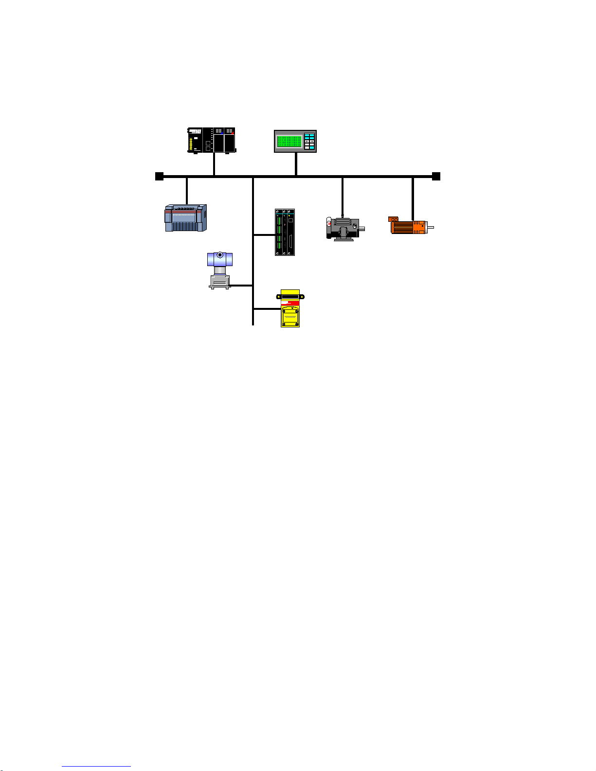
1 INTRODUCTION TO THE FIELDBUS
The Fieldbus is a digital communication system used in the industry to interconnect automation primary
elements, such as PLC’s, drives, valves, sensors, actuators, etc., as illustrated in the figure below.
Figure 1.1: Illustration of a Fieldbus network
Nowadays, there is a great variety of protocols in the market, each one with its advantages and disadvantages.
It is up to the user/project designer to evaluate what the necessary requirements for the application are, and
choose among the available options.
Rega
rdless of the choice, the main advantages of the industrial networks are:
Significant reduction in cable and installation costs;
Reduction in the
start-up
time;
More reliability and efficiency;
Addition, removal and replacement of equipment with the network under load (supply);
Integration of several suppliers (standardization);
Effective process monitoring;
Configuration of devices via the network.
By
means of the Anybus-CC communication modules, the CFW-11 supports protocols widely spread in the
industry, like DeviceNet, Profibus DP-V1, EtherNet/IP, Modbus TCP and PROFINET IO. Besides this, by means
of passive modules, RS232 and RS485/422 interfaces are also available.
Follo
wing, the characteristics for Anybus-CC modules available for the frequency inverter CFW-11 are
presented.
Phone: 800.894.0412 - Fax: 888.723.4773 - Web: www.clrwtr.com - Email: info@clrwtr.com
Page 8
2 ACCESSORY KITS
Frequency inverter CFW-11 features as accessory the Anybus-CC communication modules. Anybus-CC
modules are divided into two types: active and passive.
Active Module:
it has all the required hardware and software to perform the communication. The following
active modules are available for CFW-11:
DeviceNet
Profibus DP-V1
EtherNet/IP
Modbus TCP
PROFINET IO
Passive Module
: these passive devices work only as physical layer, not performing any processing over the
data flow. CFW-11 features the following interfaces:
RS232
RS485/422
NOTE!
For the passive modules, communication is performed through the serial interface of the product.
Therefore, the manual of serial communication Modbus RTU User’s Manual
must be referred to in
order to obtain information about how to configure and operate the product using this interface.
2.1 DEVICENET
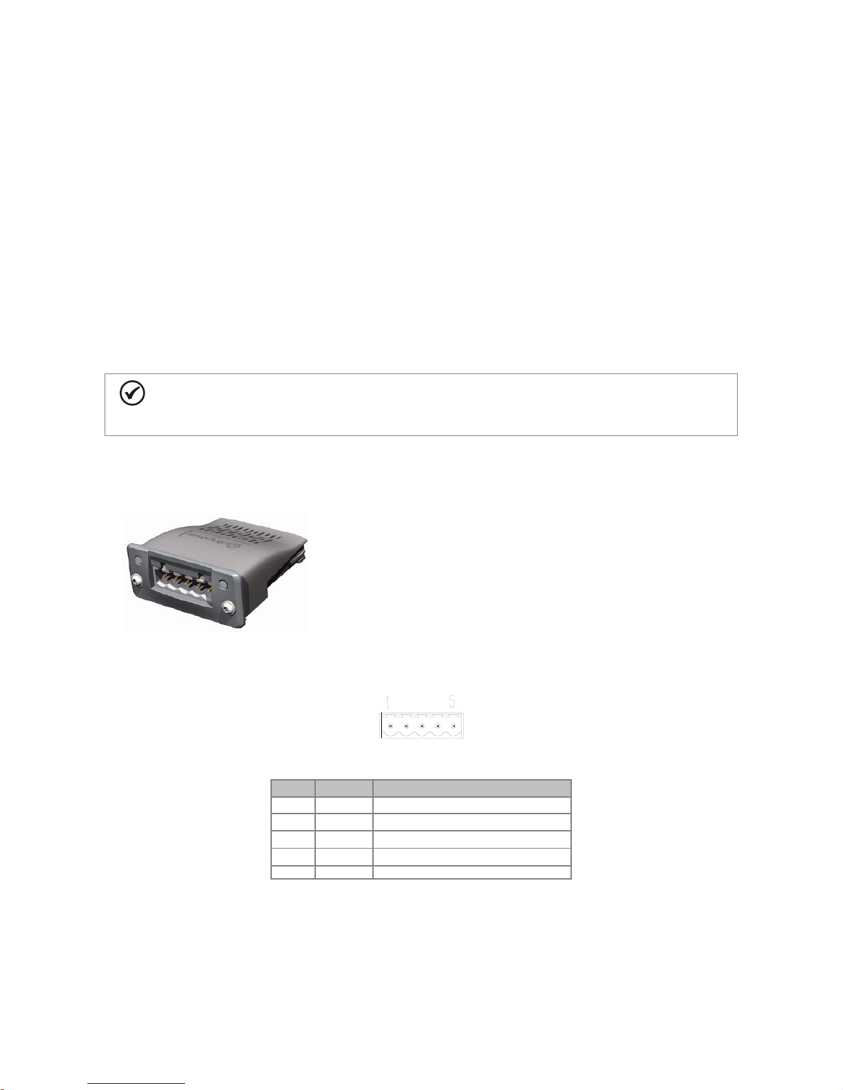
2.1.1 DEVICENET-05 Accessory
WEG part number: 11008158.
Composed by the Anybus ABCC-DEV communication module,
mounting instructions and a “torx” screw driver for fixing the
module.
ODVA certified interface.
It allows the programming of the Frequency inverter via network
configuration software.
Connector Pin Function
The DeviceNet communication module presents a male
plug-in
connector with the following pin assignment:
Table 2.1: DeviceNet plug-in connector pin assignment
Pin Name Function
1
V-
Power supply negative pole
2
CAN_L
CAN_L signal
3
Shield
Cable shield
4
CAN_H
CAN_H signal
5
V+
Power supply positive pole
Power Supply
The power supply of the network must be able to supply enough current to power up the equipment and
interfaces connected to the network. The data for individual consumption and input voltage for the DEVICENET05 accessory are presented in table 2.2.
Phone: 800.894.0412 - Fax: 888.723.4773 - Web: www.clrwtr.com - Email: info@clrwtr.com
Page 9

Table 2.2: Characteristics of power supply for the interface
Power Supply (VDC)
Minimum
Maximum
Recommended
11
25
24
Current (mA)
Typical
Maximum
36
38
Indications
DeviceNet defines two LEDs for state indication: one for the communication module (MS) and another for the
network (NS).
The MS LED indicates the conditions of the module itself. That is, whether it is able to work or not. The table
below shows the possible states:
Table 2.3: State of the DeviceNet module
LED Status Description Comments
Off Without power supply -
Green Module operating and in normal conditions -
Red Module in error Reinitializing the equipment is required.
Flashing green/red Equipment performing self-diagnosis It occurs during initialization.
The NS LED provides information about the status of the DeviceNet network. The table below presents the
description of those states.
Table 2.4: Status of the DeviceNet network
LED Status Description Comments
Off
Without power supply or not
online
Equipment is not connected to a DeviceNet network with other equipment
at the same communication rate.
Green
Online
, connected
Master has allocated a set of I/O type connection with the slave. In this
stage data exchange by means of I/O type connections does effectively
occur.
Flashing green
Online
, not connected
Slave has successfully completed the Mac ID verification procedure. This
means that the configured communication is correct (or was detected
correctly in the case of use of autobaud) and that there are no other nodes
in the network with the same address. However, in this stage, there is not a
set of I/O type connections established.
Flashing red
One or more I/O type connections
have expired
The I/O data exchange has been interrupted.
Red Serious fault in the link
It indicates that the slave cannot enter the network because of addressing
problems or due to the occurrence of
bus off
. Verify if the address is being
used by another device
, if the chosen communication rate is correct or if
there are installation problems.
Flashing green/red
Equipment performing selfdiagnosis
It occurs during initialization.
2.1.2 Installation of the DeviceNet network
For the connection of the frequency inverter using the DeviceNet interface, the following points must be
observed:
Communication Rate
Equipment with Anybus-CC interface in general allow to configure the desired communication rate, which may
vary from 125 Kbit/s to 500 Kbit/s. A communication rate (baud rate) that can be used by a device also
depends on the length of the cable used in the installation. It worth to mention that, in order to allow the
disconnection of the element from the network without damaging the bus, it is interesting to put active
terminations, which are elements that only play the role of the termination. Thus, any equipment in the network
can be disconnected from the bus without damaging the termination. The table 2.5 shows the relation between
the communication rates and the maximum lengths of the cable which can be used in the installation, according
to the recommendation of ODVA.
Phone: 800.894.0412 - Fax: 888.723.4773 - Web: www.clrwtr.com - Email: info@clrwtr.com
Page 10
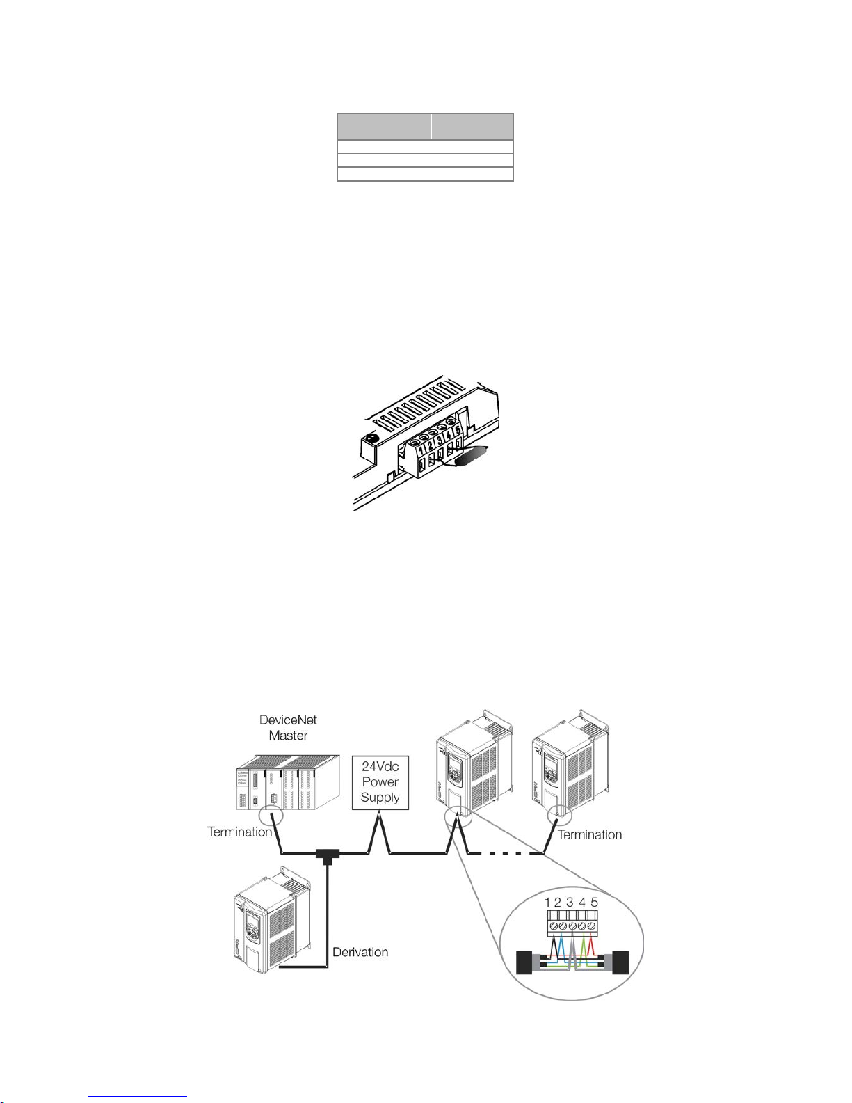
Table 2.5: Communication rates supported and cable length
Communication
Rate
Length of the
cable
500 Kbit/s
100 m
250 Kbit/s
250 m
125 Kbit/s
500 m
All the equipment of the network must be set to use the same communication rate.
Address in the DeviceNet network
Every device in the Anybus-CC network must have an address, or MAC ID, between 0 and 63. This address
must be different for each device.
Termination resistors
The use of termination resistors at the ends of the CAN bus is essential to prevent reflection in the line, which
may damage the signal transmitted and cause errors in the communication. Termination resistors of 121 Ω /
0.25 W must be connected between the signals CAN_H and CAN_L at the ends of the main bus.
Figure 2.1: Example of installation of the termination resistor
Cables
A shielded cable must be used with two pairs of wires, as specified in the DeviceNet protocol.
Installation recommendations
In order to interconnect the network nodes, it is recommended the connection of the equipment directly from
the main line, without the use of derivations. If you use derivations, the limits of length for derivation defined by
the DeviceNet specification must be observed. During the installation of the cables, you must avoid passing
them close to power cables, since that can cause errors during the transmission due to electromagnetic
interference.
Figure 2.2: Example of installation in DeviceNet network
Phone: 800.894.0412 - Fax: 888.723.4773 - Web: www.clrwtr.com - Email: info@clrwtr.com
Page 11

The grounding of the cable shield must be done only in one point, thus avoiding long current loops. This point is
normally the network own power supply. It is recommended that the network be powered in only one point, and
the power supply signal be taken to all devices by means of the cable. In case more than one power supply is
required, they must have the same point as reference.
2.1.3 Configuration of the Communication
In order to configure and use the DeviceNet module, follow the steps below:
With the module installed, during the recognition stage, a warning message will be displayed on the product
HMI, and the MS and NS LEDs test routine performed. After this stage, the MS LED must turn on in green.
Observe the content of parameter P0723. Check if the module was recognized. The detection is done
automatically and does not require the user’s intervention.
Set the parameters as desired for the application:
Address: the address of the equipment is set in parameter P0725.
Communication rate: the communication rate is set in parameter P0726.
I/O configuration: program in P0727 the number of words to be exchanged with the network master.
This same value must be set in the DeviceNet master. For this adjustment being complete, it is
necessary to program a value different from 0 (zero) in parameters P0728 to P0739 (see item 3).
Once the parameters are set, if any of the parameters described in the previous item were changed, it is
necessary to restart the equipment.
Once the equipment is set, it is necessary to configure the communication in the network master:
EDS file: register the EDS file in the network configuration tool. The EDS configuration file is supplied in a CD
together with the product. It is necessary to observe the equipment software version in order to use an EDS
file which is compatible with this version.
I/O data setting: during the configuration of the network, it is necessary to define the quantity of I/O data
communicated between master and slave, as well as the transmission method of these data. The
DeviceNet protocol defines different methods of dada exchange, seeing that the module supports the
following methods:
Polled:
communication method in which the master sends a telegram to each of the slaves of its list
(
scan list
). As soon as it receives the request, the slave immediately answers the request of the master.
This process is repeated until all slaves are polled, restarting the cycle.
Bit-strobe:
communication method in which the master sends a telegram to the network containing 8
bytes of data. Each bit of these 8 bytes represents one slave that, if addressed, answers according to
the programmed.
Change of State:
communication method in which the data exchange between master and slave only
occurs when there are changes in the values monitored/controlled up to a certain time limit. When this
limit is reached, the transmission and reception will take place even if changes have not occurred.
Cyclic:
another communication method very similar to the previous one. The only difference is the
production and consumption of messages. In this type of communication, every data exchange occurs
at regular time intervals, no matter if they have been changed or not.
If everything is correctly configured, the NS LED of the module will be on in green. It is in this condition that
cyclic data exchange effectively occurs between the slave and the master of the network.
2.1.4 Access to Parameters – Acyclic messages
Besides the I/O data (cyclic) communication, the DeviceNet protocol also defines a kind of acyclic telegram
(
explicit messages
), used especially in asynchronous tasks, such as parameter setting and configuration of the
equipment.
After the registration of the EDS file in the network configuration software, the user will have access to the full
parameter list of the equipment, which can be accessed via
explicit messages
. Each parameter is accessed
using an addressing based on class, instance and attribute. The table 2.6 shows how to address the
parameters of the CFW-11.
Phone: 800.894.0412 - Fax: 888.723.4773 - Web: www.clrwtr.com - Email: info@clrwtr.com
Page 12
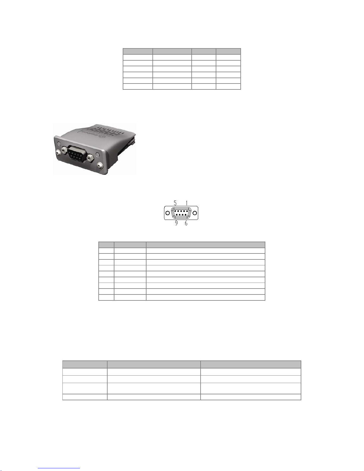
Table 2.6: Addressing of the parameters
Parameter
Class
Instance
Attribute
P0001
Class 162 (A2h)
1 5 P0002
Class 162 (A2h)
2 5 P0003
Class 162 (A2h)
3 5 ...
...
...
...
P0400
Class 162 (A2h)
400 5 ...
...
...
...
2.2 PROFIBUS
2.2.1 PROFIBUS-05 Accessory
WEG part number: 11008107.
It is composed by the Anybus ABCC-
DPV1 communication
module, mounting instructions and a “torx” screw driver for fixing
the module.
Interface certified by Profibus International.
It supports DP-V1 (acyclic messages).
Connector Pin Function
The Profibus DP-V1 communication module has a female DB9 connector with the following pin assignment:
Table 2.7: Profibus female DB9 connector pin assignment
Pin
Name
Function
1
- - 2
- - 3
B-Line (+)
RxD/TxD positive
4
RTS
Request To Send
5
GND
Reference (0 V) of the RS485 interface (isolated)
6
+5 V
+5 V for active termination (RS485 isolated power supply)
7
- - 8
A-Line (-)
RxD/TxD negative
9
-
-
Indications
Profibus defines two LEDs for status indication: one for the communication module (ST) and another for the
operating mode (OP).
The ST LED indicates the conditions of the module itself. That is, whether it is able to work or not. The table 2.8
shows the possible states:
Table 2.8: Status of the Profibus DP-V1 module
LED Status Description Comments
Off Without power supply or not initialized -
Green Module initialized -
Flashing green Initialized, but in event diagnosis
It indicates that a problem was diagnosed in the
module and an alarm was generated.
Red
In error
Reinitializing the equipment is required.
The OP LED provides information about the status of the Profibus network. The table 2.9 presents a brief
description of those states.
Phone: 800.894.0412 - Fax: 888.723.4773 - Web: www.clrwtr.com - Email: info@clrwtr.com
Page 13

Table 2.9: Status of the operating mode
LED Status Description Comments
Off Without power supply or not
online
-
Green Device
online
In this state, data exchange effectively occurs.
Flashing green
Online
but in the
clear
sate
In this state, data exchange occurs, but the
outputs are not updated.
Flashing red (1 flash) Error in parameter setting
Incorrect configuration of the Profibus
communication properties in the master of the
network.
Flashing red (2 flashes) Error in the Profibus configuration
It indicates that the quantity of I/O words (or the
order of these words) set in the master is different
from that set in the equipment.
2.2.2 Installation of the Profibus network
For the connection of the frequency inverter using the Profibus interface, the following points must be observed:
Communication Rate
It is not necessary to set the communication rate of the Profibus module because it features autobaud and,
therefore, this configuration is done in the master of the network.
Address
Every device in the Profibus network, master or slave, is identified in the network by means of an address. This
address must be different for each device. Valid values: 1 to 126.
Termination resistors
For each segment of the Profibus DP network, it is necessary to enable a termination resistor at the ends of the
main bus. Connectors suitable for the Profibus network that feature a switch to enable the resistor may be used,
but the switch must only be enabled (ON position) if the equipment is the first or last element in the segment. It
is worth to mention that, in order to allow the disconnection of the element from the network without damaging
the bus, it is interesting to put active terminations, which are elements that only play the role of the termination.
So any equipment in the network can be disconnected from the bus without damaging the termination.
Cables
It is recommended that the installation be done with A-type cable, whose features are described in table 2.10.
The cable has a pair of wires that must be shielded and twisted in order to guarantee greater immunity to
electromagnetic interference.
Table 2.10: Properties of cable A-type cable
Impedance
135 to 165 Ω
Capacitance
30 pf/m
Resistance in loop
110 Ω/km
Diameter of the cable
> 0.64 mm
Cross section of the wire
> 0.34 mm
Connectors
There are different types of connectors specifically designed for applications in the Profibus network. For CFW-
11 frequency inverter, it is recommended to use connectors with cable connection in 180 degrees, because, in
general, connectors with different angles can not be used due to mechanical characteristics of the product.
Installation recommendations
The Profibus DP protocol, using physical medium RS485, allows the connection of up to 32 devices per
segment, without the use of repeaters. With repeaters, up to 126 addressable devices can be connected to the
network. Each repeater must also be included as a device connected to the segment, although it will not take
an address in the network.
It is recommended that the connection of all the devices present in the Profibus DP network be done from the
main bus. In general, the connector of the Profibus network itself has one input and one output for the cable,
allowing the connection to be taken to the other points of the network. Derivations from the main line are not
recommended, especially for communication rates over or equal to 1.5Mbps.
Phone: 800.894.0412 - Fax: 888.723.4773 - Web: www.clrwtr.com - Email: info@clrwtr.com
Page 14

Figure 2.3: Example of installation of the Profibus DP network
The Profibus DP network cables must be laid separately (and far away if possible) from the power cables. All the
drives must be properly grounded, preferably at the same ground point. The Profibus cable shield must also be
grounded. The DB9 connector itself already has a connection with the protective ground and, therefore, makes
the connection of the shield to the ground when the Profibus cable is connected to the drive. However a better
connection, implemented by clamps that connect the shield to a ground point, is also recommended.
2.2.3 Configuration of the Module
In order to configure and use the Profibus DP-V1 module, follow the steps below:
With the module installed, during the acknowledgement stage, a warning message will be displayed on the
product HMI, and the ST and OP LEDs test routine performed. Then the ST LED of the module must turn
on in green.
Observe the content of parameter P0723. Check if the module was recognized. The detection is done
automatically and does not require the user’s intervention.
Set the parameters as desired for the application:
Address: the address of the equipment is set in parameter P0725.
I/O configuration: Program in P0727 the number of words to be exchanged with the network master.
This same value must be set in the Profibus master. For this adjustment being complete, it is necessary
to program a value different from 0 (zero) in parameters P0728 to P0739 (see item 3).
Once the parameters are set, if any of the parameters described in the previous item are changed, it is
necessary to restart the equipment.
Once the equipment is set, it is necessary to configure the communication in the master of the network:
GSD file: every element of the Profibus DP network has an associated configuration file with extension GSD.
This file describes the features of each device and it is used by the configuration tool of the master of the
Profibus DP network. During the configuration of the master, the GSD configuration file, supplied with the
equipment, must be used. This file must be registered in the master of the Profibus DP network. The
module will be recognized as “
Anybus CompactCom DPV1
” in the category “
General
”.
I/O data setting: add the CFW-11 to the device list of the master, setting the number of I/O words
according to parameter P0727.
If everything is correctly configured, the OP LED of the module will be on in green. It is in this condition that
cyclic data exchange effectively occurs between the drive and the master of the network.
NOTE!
In the configuration software of the Profibus network, first you must select all the input words (
inputs
)
and then select the output words (
outputs)
, according to parameter P0727.
Phone: 800.894.0412 - Fax: 888.723.4773 - Web: www.clrwtr.com - Email: info@clrwtr.com
Page 15

NOTE!
For further information on the parameters mentioned above, refer to item 3.
2.2.4 Access of the Parameter – Acyclic Messages
The PROFIBUS-05 communication kit allows parameter reading/writing services by means of DP-V1 acyclic
functions. The parameter mapping is done based on the slot and index addressing, as showed in the formula
below:
Slot: (parameter number - 1) / 255.
Index: (parameter number - 1) MOD 255.
NOTE: MOD represents the remainder of the integer division.
2.3 ETHERNET/IP
2.3.1 ETHERNETIP-05 and ETHERNET-2P-05 Accessory
Ethernet-05 part number: 10933688 (1 Ethernet port).
Ethernet-2P-05 part number: 12272760 (2 Ethernet ports with
integrated switch).
Composed by the Anybus ABCC-EIP communication module,
mounting instructions and a “torx” screw driver for fixing the
module.
Standard RJ45 connector.
ODVA certified interface.
Connector
The EtherNet/IP communication module has a standard female RJ45 connector (T-568A or T-568B).
Indications
EtherNet/IP defines two LEDs for status indication: one for the communication module (MS) and another for the
network (NS).
The MS LED indicates the conditions of the module itself. That is, whether it is able to work or not. The table
below shows the possible states:
Table 2.11: State of the EtherNet/IP module
LED Status Description Comments
Off Without power supply -
Green Module controlled by a scanner in RUN mode. In this state, data exchange effectively occurs.
Flashing green Not configured or scanner in IDLE mode
In this stage there is no cyclic data communication
with the scanner, or the scanner is in IDLE mode.
Red Major fault
Internal error of the module. Equipment must be
reinitialized.
Flashing red Recoverable fault
Internal error of the module, but the return to the
normal state occurs automatically after the cause of
the fault is corrected.
Flashing green/red
Equipment performing self-diagnosis
It occurs during initialization.
The NS LED indicates the conditions of the EtherNet/IP network.
Phone: 800.894.0412 - Fax: 888.723.4773 - Web: www.clrwtr.com - Email: info@clrwtr.com
Page 16

Table 2.12: Status of the EtherNet/IP network
LED Status Description Comments
Off Without power supply or IP address
The software IPconfig must be used to configure the
communication module address.
Green
Online
, connected
Master has allocated a set of I/O type connection
with t
he slave. In this stage data exchange by means
of I/O type connections does effectively occur.
Flashing green
Online
, not connected
In this stage, there is not a set of I/O type
connections established.
Red Major fault or duplicated IP address
Equipment must be reinitialized to exit the fault state.
Check the IP addresses in the network.
Flashing red
One or more I/O type connections
have expired
The I/O data exchange has been interrupted.
Flashing green/red
Equipment performing self-diagnosis
It occurs during initialization.
The LINK LED indicates the state of the physical connection of the network, as well as the activity in the bus.
Table 2.13: Status of the connection
LED Status Description Comments
Off Without link Without connection, without activity
Green Link Ethernet link established but without data exchange.
Flashing green Activity in the bus
It effectively indicates that there is exchange of
telegrams with the network.
2.3.2 Installation of the Ethernet network
For the connection of the frequency inverter using the Ethernet interface, the following points must be observed:
Communication Rate
The Ethernet interfaces of the Anybus-CC communication cards can communicate using the 10 or 100 Mbps
rates in
half
or
full
duplex mode. As default, the modules are configured with automatic detection of the
communication rate.
MAC Address
Each Anybus-CC module has a unique MAC address, which is indicated on a label in its lower part. This MAC
address may be useful during the stage of configuration of the interface, when it may be necessary to make a
differentiation in case several modules are simultaneously configured, and it must be written down before its
installation.
Address in the Ethernet network
Every device in an Ethernet network needs an IP address and subnet mask.
The IP addressing is unique in the network, and each device must have a different IP. The subnet mask is used
to define which IP address range is valid in the network.
These attributes can be automatically configured by means of a DHCP server present in the network, as long as
this option is enabled in the Anybus-CC module.
Cables
To perform the installation, it is recommended the use of shielded Ethernet cables specific for use in industrial
environment.
Installation recommendations
Each cable segment must have at most 90 m.
It must be used a direct cable to connect the module to a concentrating element (
switch
), or a
cross-over
cable for direct connection between the module and the PC/CLP.
As for topology, there are two models of Anybus-CC card: with one or two Ethernet ports.
For the models with one port, the most usual topology is star, exactly as it is done with computer
networks. In this case all the equipment must be connected to a concentrating element (switch).
Phone: 800.894.0412 - Fax: 888.723.4773 - Web: www.clrwtr.com - Email: info@clrwtr.com
Page 17

Figure 2.4: Star topology.
The models with two ports have an integrated switch. Thus, besides the connection of the equipment in
star for a concentrating element, it is also possible to make the connection in
daisy chain
, allowing a
topology equivalent to a bus.
Figure 2.5: D
aisy chain topology.
2.3.3 Configuration of the Ethernet Interface
In order to configure the Ethernet interface of the communication modules, it is necessary to connect the
module to a PC to use the following software:
HMS Anybus IPconfig
This software is used to program the IP address of the module. When you execute this software, it will
automatically scan the network in order to find out which modules are connected. The modules found will be
listed, showing the information of IP address, subnet, gateway, etc. If more than a module is found, it is
necessary to make the differentiation through the MAC address indicated in the lower part of the Anybus-CC
module.
Figure 2.6: HMS Anybus IPconfig.
To edit this information, you just click twice on the desired module to open new window, where you can modify
these fields.
PC
(192.168.0.2)
CLP
EtherNet/IP module
(192.168.0.1)
Switch
HMI
(192.168.0.5)
Remote I/O
(192.168.0.4)
Drive
(192.168.0.3)
Phone: 800.894.0412 - Fax: 888.723.4773 - Web: www.clrwtr.com - Email: info@clrwtr.com
Page 18

Figure 2.7: IPconfig software information editing.
Web Browser
In case the IP address is known, it is possible to use a web browser to access the data configuration of the
Anybus-CC module. Typing the IP address in the address bar of the browser, you will see a webpage with links
for the configurations of the interface or for the data of the equipment.
In the interface configurations, you will find several fields to program IP address, subnet, DHCP, among others.
Figure 2.8: Webpage of interface configuration
The data mapped in the input/output (I/O) areas can also be accessed by means of the web browser through
the link “Parameter Data”. Through this page, it is possible to read the monitoring data, as well as to modify the
equipment control data.
Phone: 800.894.0412 - Fax: 888.723.4773 - Web: www.clrwtr.com - Email: info@clrwtr.com
Page 19

Figure 2.9: Web page with input/output data
NOTE!
If there is cyclic communication between the module and the master of the network, the control data
sent by the master will overwrite the data sent through this page. Thus, the commands sent by this
page will only be executed in case the module is in the offline state.
2.3.4 Configuration of the Communication
In order to configure and use the EtherNet/IP module, follow the steps below:
With the module installed, during the recognition stage, a warning message will be displayed on the product
HMI, and the MS and NS LEDs test routine performed. After this stage, the MS LED must turn on in green.
Observe the content of parameter P0723. Check if the module was recognized. The detection is done
automatically and does not require the user’s intervention.
Set the parameters as desired for the application:
Configurations of IP address and communication rate are explained in item 2.3.3.
I/O configuration: program in P0727 the number of words to be exchanged with the network master.
This same value must be set in the EtherNet/IP scanner. For this adjustment being complete, it is
necessary to program a value different from 0 (zero) in parameters P0728 to P0739 (see item 3).
Once the parameters are set, if any of the parameters described in the previous item are changed, it is
necessary to restart the equipment.
Once the equipment is set, it is necessary to configure the communication in the master of the network:
EDS file: register the EDS file in the network configuration file. The EDS configuration file is supplied in a CD
together with the product.
For the configuration of the master, besides the IP address used by the EtherNet/IP module, it is necessary
to indicate a number of the instances of I/O and the quantity of data exchanged with the master in each
instance. For the EtherNet/IP communication module, the following values must be programmed:
Input instance (input): 100
Output instance (output): 150
The EtherNet/IP module is described in the network as “Generic Ethernet Module”. Using these
configurations it is possible to program the master of the network to communicate with the equipment.
If everything is correctly configured, the NS LED of the module will be on in green. It is in this condition that
cyclic data exchange effectively occurs between the slave and the master of the network.
2.3.5 Access to Parameters – Acyclic messages
Besides the cyclic data communication, the EtherNet/IP protocol also defines a kind of acyclic telegram, used
especially in asynchronous tasks, such as parameter setting and configuration of the equipment. The table 2.6
brings the class, instance and attribute for the access of the parameters of the equipment.
Phone: 800.894.0412 - Fax: 888.723.4773 - Web: www.clrwtr.com - Email: info@clrwtr.com
Page 20

2.4 MODBUS TCP
2.4.1 MODBUSTCP-05 Accessory
WEG part number: 11550476.
Composed by the Anybus ABCC-EIT communication module,
mounting instructions and a “torx” screw driver for fixing the
module.
Standard RJ45 connector.
Connector
The Modbus TCP communication module has a standard female RJ45 connector (T-568A or T-568B).
Indications
Modbus TCP defines two LEDs for status indication: one for the communication module (MS) and another for
the network (NS).
The M
S LED indicates the conditions of the module itself. That is, whether it is able to work or not. Table 2.14
shows the possible states:
Table 2.14: Status of the Modbus TCP module
LED Status Description Comments
Off Without power supply -
Green Normal operation -
Red Serious fault.
Internal error of the module. Equipment must be
reinitialized.
Flashing red
Recoverable fault or c
onflict of IP
address
Internal error of the module, but the return to the
normal state occurs automatically after the cause of
the fault is corrected.
Check the IP addresses in the network.
Flashing green/red
Equipment performing self-diagnosis
It occurs during initialization.
The N
S LED indicates the conditions of the Modbus TCP network.
Table 2.15: Status of the Modbus TCP network
LED Status Description Comments
Off Without power supply or IP address
The software IPconfig must be used to configure the
communication module address.
Green Module is in Process Active or Idle state -
Flashing green Waiting for connections -
Red Major fault or conflict of IP address
Equipment must be reinitialized to exit the fault state.
Check the IP addresses in the network.
Flashing red
Timeout
The data exchange has been interrupted.
Flashing green/red
Equipment performing self-diagnosis
It occurs during initialization.
The
LINK LED indicates the state of the physical connection of the network, as well as the activity in the bus.
Table 2.16: Status of the connection
LED Status Description Comments
Off Without link Without connection, without activity
Green Link
Ethernet link established but without data exchange
between master and slave.
Flashing green Activity in the bus
It effectively indicates that there is data exchange
between the master and the slave.
2.4.2 Installation of the Ethernet Network
For the connection of the frequency inverter using the Ethernet interface, refer to item 2.3.2.
Phone: 800.894.0412 - Fax: 888.723.4773 - Web: www.clrwtr.com - Email: info@clrwtr.com
Page 21

2.4.3 Configuration of the Ethernet Interface
To configure the Ethernet interface of the communication module, refer to item 2.3.3.
2.4.4 Configuration of the Communication
In order to configure and use the Modbus TCP, follow the steps below:
With the module installed, during the recognition stage, a warning message will be displayed on the product
HMI, and the MS and NS LEDs test routine performed. After this stage, the MS LED must turn on in green.
Observe the content of parameter P0723. Check if the module was recognized. The detection is done
automatically and does not require the user’s intervention.
Set the parameters as desired for the application:
Configurations of IP address and communication rate are explained in item 2.3.3.
I/O configuration: program in P0727 the number of words to be exchanged with the network master.
For this adjustment being complete, it is necessary to program a value different from 0 (zero) in
parameters P0728 to P0739 (see item 3).
Once the parameters are set, if any of the parameters described in the previous item are changed, it is
necessary to restart the equipment.
Once the equipment is set, it is necessary to configure the communication in the master of the network:
Configure the master to access the Anybus I/O words as per the memory map presented in item 2.4.5.
To configure the timeout of the communication and order of the bytes, use the web browser according to
the figure 2.10.
Figure 2.10: Webpage with configuration of the timeout and order of the bytes
The field “Comm tmo” is used to configure the timeout of the TCP connection and the field Process tmo
allows to program the time for the detection of communication error.
The field “Word order” configures the order of the
bytes
of each word in
little endian
(byte 1 most significant)
or
big endian
(byte 0 least significant).
Connect the network cable to the module.
If everything is correctly configured, the NS LED of the module will be on in green and the LINK LED will
start to flash indicating normal activity in the network.
NOTE!
For further information on the parameters mentioned above, refer to item 3.
Phone: 800.894.0412 - Fax: 888.723.4773 - Web: www.clrwtr.com - Email: info@clrwtr.com
Page 22

2.4.5 Addressing of the data
Modbus TCP does not define a channel of cyclic data dedicated like in other networks. However, in the AnybusCompactCom module, the I/O words can be accessed by the network by means of dedicated registers.
The I
/O words can be accessed as bits (Coils and Discrete Inputs) or as registers of 16 bits (Holding Registers
and Input Registers).
The p
arameters of the drive can be accessed only as holding registers.
The M
odbus mapping is presented in the table below:
Table 2.17: Addressing for Holding Registers
Address range Description
0000h ... 00FFh Anybus Writing Words
0100h ... 01FFh Anybus Reading Words
0210h ... FFFFh
Parameters of the drive
To find the address of the register corresponding to
the parameter:
ADDR = 210h + (Parameter Number – 1)
Examp
le:
P0003 = 210h + (3h – 1h) = 212h
P0100 = 210h + (64h – 1h) = 273h
Table 2.18: Addressing for Input Registers
Address range Description
0000h ... 00FFh Anybus Reading Words
Table 2.19: Addressing for Coils
Address range Description
0000h ... 0FFFh Anybus Writing Words
Table 2.20: Addressing for Discrete Inputs
Bit address range Description
0000h ... 0FFFh Reading Words Anybus
NOTE!
Writings in reading words will have no effect, and the reading of not used registers will return to value
zero.
2.5 PROFINET
2.5.1 PROFINETIO-05 Accessory
WEG part number: 11550548.
Composed by the Anybus ABCC-EIT communication module,
mounting instructions and a “torx” screw driver for fixing the
module.
Two Standard RJ45 connectors.
Connector
The PROFINET IO communication module has two standard female RJ45 connectors (T-568A or T-568B). It
features integrated switch, enabling the connection in
daisy chain
.
Phone: 800.894.0412 - Fax: 888.723.4773 - Web: www.clrwtr.com - Email: info@clrwtr.com
Page 23

Indications
PROFINET IO defines two LEDs for status indication: one for the communication module (MS) and another for
the network (NS). Figure 2.11 describes the indication LEDs.
Figure 2.11: Description of the indication LEDs of the PROFINET module
The MS LED (2) indicates the conditions of the module itself. Table 2.21 shows the possible states:
Table 2.21: Status of the operating mode
Status Description COMMENTS
Off Without power supply -
Green Normal operation -
Flashing green - flashes
once
Present diagnosis No used.
Flashing green - flashes
twice
acknowledgement
Signaling used by an engineering tool to recognize
the equipment in the network.
Red Major fault
Internal error in the communication between the
Anybus-CC module
and drive (Exception).
Equipment must be reinitialized.
Flashing red - flashes once Configuration error
It indicated that the quantity of I/O words (or the
order of these words) was not correctly configured in
the master of the network.
Flashing red - flashes once IP address not configured
The software IPconfig must be used to configure the
communication module address or use the
PROFINET master to choose the automatic
configuration of the IP address.
Flashing red - flashes three
times
Station name not configured
The equipment must be configured in a PROFINET
network so that the station name is attributed by the
master of the network.
Flashing red - flashes three
times
Internal error Equipment must be reinitialized.
Flashing green/red
Equipment performing self-diagnosis
It occurs during initialization.
The NS LED (1) indicates the conditions of the PROFINET network.
Table 2.22: Status of the PROFINET network
LED Status Description Comments
Off Offline
Module without power supply
Without connection with the master of the network.
Green Online (RUN)
Connection with the master of the network
established.
Master of the network in RUN.
Flashing green Online (STOP)
Connection with the master of the network
established.
Master of the network in STOP.
The LINK LEDs (5 and 6) indicates the state of the physical connection of the network, as well as the activity in
the bus.
Table 2.23: Status of the connection
LED Status Description Comments
Off Without link Without connection, without activity.
Green Link
Ethernet link established but without data exchange
between master and slave.
Flashing green Activity in the bus
It indicates that there is data exchange between the
master and the slave.
Phone: 800.894.0412 - Fax: 888.723.4773 - Web: www.clrwtr.com - Email: info@clrwtr.com
Page 24

2.5.2 Installation of the Ethernet Network
For the connection of the frequency inverter using the Ethernet interface, refer to item 2.3.2.
2.5.3 Configuration of the Ethernet Interface
To configure the Ethernet interface of the communication module, refer to item 2.3.3.
2.5.4 Configuration of the Communication
In order to configure and use the PROFINET IO module, follow the steps below:
With the module installed, during the recognition stage, a warning message will be displayed on the product
HMI, and the MS and NS LEDs test routine performed. After this stage, the MS LED must turn on in green.
Observe the content of parameter P0723. Check if the module was recognized. The detection is done
automatically and does not require the user’s intervention.
Set the parameters as desired for the application:
Configurations of IP address and communication rate are explained in item 2.3.3.
I/O configuration: program in P0727 the number of words to be exchanged with the network master.
This same value must be set in the PROFINET master. For this adjustment being complete, it is
necessary to program a value different from 0 (zero) in parameters P0728 to P0739 (see item 3).
Once the parameters are set, if any of the parameters described in the previous item are changed, it is
necessary to restart the equipment.
Once the equipment is set, it is necessary to configure the communication in the master of the network:
GSD file: register the GSD file for PROFINET (GSDML) in the configuration software of the network. The
GSD configuration file is supplied in a CD together with the product. The module will be recognized as
“
Anybus CompactCom PRT 2-Port
” in the category “
General
”.
For the configuration of the master, the following points must be observed:
The same quantity of data set in the slave must be set in the master. These data must be programmed
observing the following order: first all input words and then all output words
;
The IP address of the slave can be configured manually (via IPconfig) or attributed automatically by the
PROFINET master (in case it has this function);
The network topology must be informed, indicating precisely the connections between the PROFINET
equipment.
NOTE!
For further information on the parameters mentioned above, refer to item 3.
2.5.5 Access to Parameters – Acyclic messages
Besides the cyclic communication, the PROFINET protocol also allows to perform acyclic requests used
especially to transmit diagnosis data, parameter setting and configuration of the equipment. For the drive which
uses the Anybus module, practically all the parameters can be accessed by means of this way of
communication.
The PROFINET protocol defines the following structures for the addressing of the components used in the
configuration of the network:
AR (Application Relation);
API (Application Process Identifier);
Slot;
Subslot.
AR and API are used to identify the Anybus module during the stage of configuration of the network.
Slot/Subslot are not relevant for acyclic access of the data for the drive. Once the module is identified, the
parameters are accessed indicating the Index and the size of the data (Length) accessed:
Index: it represents the number of the parameter;
Length: the size of the data accessed. All the parameters of the drive are accessed as Word (2 bytes).
Phone: 800.894.0412 - Fax: 888.723.4773 - Web: www.clrwtr.com - Email: info@clrwtr.com
Page 25

2.6 RS232
2.6.1 RS232-05 Accessory
WEG part number: 11008160.
Composed by the Anybus ABCC-
RS232 communication
module, mounting instructions and a “torx” screw driver for
fixing the module.
It allows transmission rates up to 57.6 kbps.
Connector Pin Function
The RS232 communication module presents a male DB9 connector with the following pin assignment:
Table 2.24: RS232 DB9 male connector pin assignment
Pin Name Function
1
-
-
2
RxD
RS232 data reception
3
TxD
RS232 data transmission
4
- - 5
GND
Reference (0 V) of the interface
6
-
-
7
RTS
Request To Send
8
-
-
9
-
-
Indications
PWR LED: Green LED. When on, it indicates that the module is powered.
Connection with the Network
For the connection of the device using the passive RS232 interface, the following points must be observed:
Use good quality cables, preferably shielded.
Keep the cable length within the limits stipulated by the standard, normally about 10m.
Avoid passing the cables close to power cables.
2.7 RS485
2.7.1 RS485-05 Accessory
WEG part number: 11008161.
Composed by the Anybus ABCC-RS485, mounting instructions
and a “torx” screw driver for fixing the module.
It allows transmission rates up to 57.6 kbps.
Connector Pin Function
The RS485/422 interface module presents a female DB9 connector with the following pin assignment:
Phone: 800.894.0412 - Fax: 888.723.4773 - Web: www.clrwtr.com - Email: info@clrwtr.com
Page 26

Table 2.25: RS485/422 female DB9 connector
Pin
RS422 Mode
RS485 Mode
Function
1
Term Pwr
Term Pwr
+5 V for active termination (isolated)
2
-
-
-
3
-
-
-
4
Mode Select
Mode Select
Not connected: RS485 mode
Connected to GND: RS422 mode
5
GND
GND
Reference (0 V) for the interface circuit (isolated)
6
RxD
-
Data reception line in RS422 mode
Not connected in RS485 mode
7
RxD (inverted)
-
8
TxD
RxD/TxD
Data transmission line in RS422 mode
Bidirectional data line in RS485 mode.
9
TxD (inverted)
RxD/TxD (inverted)
Indications
PWR LED: Green LED. When on, it indicates that the module is powered.
Connection with the Network
For the connection of the device using the passive RS485 interface, the following points must be observed:
Use
good quality shielded cables.
Keep the cable length within the limits stipulated by the standard, normally about 1000 meters.
Avoid passing the communication cables close to power cables.
Put termination resistors between the data signal wires (RxD/TxD and TxD/RxD) at the network extreme
nodes. This will avoid reflections in the line.
Phone: 800.894.0412 - Fax: 888.723.4773 - Web: www.clrwtr.com - Email: info@clrwtr.com
Page 27

3 PROGRAMMING
Next, only the CFW-11 frequency inverter parameters related to the Anybus-CC communication will be
presented.
3.1 SYMBOLS FOR THE PROPERTIES DESCRIPTION
RO
Read-only parameter
CFG
Parameter that can be changed only with a stopped motor
NET
Parameter visible on the HMI if the device has the network interface installed – RS232, RS485, CAN,
Anybus-CC, Profibus – or if the USB interface is connected
P0105 – 1ST/2ND RAMP SELECTION
P0220 – LOCAL/REMOTE SELECTION SOURCE
P0221 – SPEED REFERENCE SELECTION – LOCAL SITUATION
P0222 – SPEED REFERENCE SELECTION – REMOTE SITUATION
P0223 – FORWARD/REVERSE SELECTION – LOCAL SITUATION
P0224 – RUN/STOP SELECTION – LOCAL SITUATION
P0225 – JOG SELECTION – LOCAL SITUATION
P0226 – FORWARD/REVERSE SELECTION – REMOTE SITUATION
P0227 – RUN/STOP SELECTION – REMOTE SITUATION
P0228 – JOG SELECTION – REMOTE SITUATION
These parameters are used in the configuration of the command source for the CFW-11 frequency inverter local
and remote situations. In order that the device be controlled through the Anybus-CC interface, the options
‘Anybus-CC’ available in these parameters, must be selected.
The detailed description of these parameters is found in the CFW-11 programming manual.
P0313 – COMMUNICATION ERROR ACTION
Range: 0 = Inactive Default: 1
1 = Disable via Run/Stop
2 = Disable via General Enable
3 = Change to Local
4 = Change to Local keeping commands and reference
5 = Causes a Fault
Properties: CFG
Access groups 01 PARAMETER GROUPS
via HMI: ∟49 Communication
∟111 Status and commands
Description:
It allows the selection of the action to be executed by the device, if it is controlled via network and a
communication error is detected.
Phone: 800.894.0412 - Fax: 888.723.4773 - Web: www.clrwtr.com - Email: info@clrwtr.com
Page 28

Table 3.1: P0313 options
Options
Description
0 = Inactive
No action is taken and the drive remains in the existing status.
1 = Disable via Run/Stop
A stop command with deceleration ramp is executed and the
motor stops according to the programmed deceleration ramp.
2 = Disable via General Enable
The drive is disabled by removing the General Enabling and the
motor coasts to stop.
3 = Change to Local
The drive commands change to Local.
4 = Change to Local keeping
commands and reference
The drive commands change to Local, but the status of the
enabling and speed reference commands received via network
are kept, providing that the drive has been programmed to use in
Local mode the commands via HMI, or 3-
wire start/stop and
speed reference via either HMI or electronic potentiometer.
5 = Causes a Fault
Instead of an alarm, the communication error causes an drive
fault, so that a drive fault reset
becomes necessary in order to
restore normal operation.
The following events are considered communication errors:
Anybus-CC communication:
A129 alarm/F229 fault: Anybus is offline
A130 alarm/F230 fault: Anybus access error
The actions described in this parameter are executed by means of the automatic writing of the selected actions
in the respective bits of the interface control words. Therefore, in order that the commands written in this
parameter be effective, it is necessary that the device be programmed to be controlled via the used network
interface (with exception of option “Causes a Fault”, which blocks the equipment even if it is not controlled by
network). This programming is achieved by means of parameters P0220 to P0228.
P0680 – STATUS WORD
Range: 0000h to FFFFh Default: Properties: RO
Access groups 01 PARAMETER GROUPS
via HMI: ∟49 Communication
∟111 Status and commands
Description:
It allows the device status monitoring. Each bit represents a specific status:
Bits
15
14
13
12
11
10 9 8 7 6 5 4
3 to 0
Function
Fault condition
(PID) Automatic
Undervoltage
LOC/REM
JOG
Speed direction
Active General
Enable
Motor Running
Alarm condition
In configuration
mode
Second ramp
Active fast stop
Reserved
Phone: 800.894.0412 - Fax: 888.723.4773 - Web: www.clrwtr.com - Email: info@clrwtr.com
Page 29

Table 3.2: P0680 parameter bit functions
Bits
Values
Bits 0 to 3
Reserved.
Bit 4
Active quick stop
0: The fast stop command is not active.
1: The drive is executing the fast stop command.
Bit 5
Second ramp
0: The drive is configured to use the first ramp values, programmed in P0100 and P0101, as the motor
acceleration and deceleration ramp times.
1: The drive is configured to use the second ramp values, programmed in P0102 and P0103, as the motor
acceleration and deceleration ramp times.
Bit 6
In configuration mode
0: The drive is operating normally.
1: The drive is in the configuration mode. It indicates a special condition during which the drive cannot be
enabled:
Executing the self-tuning routine
Executing the oriented start-up routine
Executing the HMI copy function
Executing the flash memory card self-guided routine
There is a parameter setting incompatibility
There is no power at the drive power section
Bit 7
Alarm condition
0: The drive is not in alarm condition.
1: The drive is in alarm condition.
Note: The alarm number can be read by means of the parameter P0048 – Present Alarm.
Bit 8
Motor Running
0: The motor is stopped.
1: The drive is running the motor at the set point speed, or executing either the acceleration or the
deceleration ramp.
Bit 9
Active General Enable
0: General Enable is not active.
1: General Enable is active and the drive is ready to run the motor.
Bit 10
Speed direction
0: The motor is running in the reverse direction.
1: The motor is running in the forward direction.
Bit 11
JOG
0: Inactive JOG function.
1: Active JOG function.
Bit 12
LOC/REM
0: Drive in Local mode.
1: Drive in Remote mode.
Bit 13
Undervoltage
0: No Undervoltage.
1: With Undervoltage.
Bit 14
Manual/ Automatic
0: PID in manual mode.
1: PID in Automatic mode.
Bit 15
Fault condition
0: The drive is not in a fault condition.
1: The drive has detected a fault.
Note: The fault number can be read by means of the parameter P0049 – Present Fault.
P0681 – MOTOR SPEED IN 13 BITS
Range: - 32768 to 32767 Default: Properties: RO
Access groups 01 PARAMETER GROUPS
via HMI: ∟49 Communication
∟111 Status / Commands
Description:
It allows monitoring the motor speed. This word uses 13-bit resolution with signal to represent the motor
synchronous speed:
P0681 = 0000h (0 decimal) → motor speed = 0
P0681 = 2000h (8192 decimal) → motor speed = synchronous speed
Int
ermediate or higher speed values in rpm can be obtained by using this scale. E.g. for a 4 pole motor and
1800 rpm of synchronous speed if the value read is 2048 (0800h), then, to obtain the speed in rpm one must
calculate:
Phone: 800.894.0412 - Fax: 888.723.4773 - Web: www.clrwtr.com - Email: info@clrwtr.com
Page 30

8192 => 1800 rpm
2048 => Speed in rpm
Speed in rpm = 1800 × 2048
8192
Speed in rpm = 450 rpm
Negative values in this parameter indicate that the motor is running in the reverse direction.
P0686 – ANYBUS-CC CONTROL WORD
Range: 0000h to FFFFh Default: 0000h
Properties: Access groups 01 PARAMETER GROUPS
via HMI: ∟49 Communication
∟111 Status and commands
Description:
It is the device Anybus-CC interface control word. This parameter can only be changed via Anybus-CC
interface. For the other sources (HMI, etc.) it behaves like a read-only parameter.
In order to have those commands executed, it is necessary to program the equipment to be controlled via
Anybus-CC. This programming is achieved by means of parameters P0105 and P0220 to P0228.
Each bit of this word represents a command that can be executed.
Bits
15 to 8
7 6 5 4 3 2 1
0
Function
Reserved
Fault reset
Quick stop
Second ramp
LOC/REM
JOG
Speed direction
General enable
Run/Stop
Table 3.3: P0686 parameter bit functions
Bits
Values
Bit 0
Run/Stop
0: It stops the motor with deceleration ramp.
1: The motor runs according to the acceleration ramp until reaching the speed reference value.
Bit 1
General enable
0: It disables the drive, interrupting the supply for the motor.
1: It enables the drive allowing the motor operation.
Bit 2
Speed direction
0: To run the motor in a direction opposed to the speed reference.
1: To run the motor in the direction indicated by the speed reference.
Bit 3
JOG
0: It disables the JOG function.
1: It enables the JOG function.
Bit 4
LOC/REM
0: The drive goes to the Local mode.
1: The drive goes to the Remote mode.
Bit 5
Second ramp
0: The drive uses the first ramp values, programmed in P0100 and P0101, as the motor acceleration
and deceleration ramp times.
1: The drive is configured to use the second ramp values, programmed in P0102 and P0103, as the
motor acceleration and deceleration ramp times.
Bit 6
Quick stop
0: It does not execute the quick stop command.
1: It executes the quick stop command.
Note: This function is not allowed with control types (P0202) V/f or VVW.
Bit 7
Fault reset
0: No function.
1: If in a fault condition, then it executes the reset.
Bits 8 to 15
Reserved.
Phone: 800.894.0412 - Fax: 888.723.4773 - Web: www.clrwtr.com - Email: info@clrwtr.com
Page 31

P0687 – ANYBUS-CC SPEED REFERENCE
Range: -32768 to 32767 Default: 0
Properties: Access groups 01 PARAMETER GROUPS
via HMI: ∟49 Communication
∟111 Status and commands
Description:
It allows programming the motor speed reference via the Anybus-CC interface. This parameter can only be
changed via Anybus-CC interface. For the other sources (HMI, etc.) it behaves like a read-only parameter.
In order that the reference written in this parameter be used, it is necessary that the drive be programmed to
use the speed reference via Anybus-CC. This programming is achieved by means of parameters P0221 and
P0222.
This word uses a 13-bit resolution with signal to represent the motor synchronous speed.
P0687 = 0000h (0 decimal) → speed reference = 0
P0687 = 2000h (8192 decimal) → speed reference = synchronous speed
Intermediate or higher reference values can be programmed by using this scale. E.g. for a 4 pole motor and
1800 rpm of synchronous speed, to obtain a speed reference of 900 rpm one must calculate:
1800 rpm => 8192
900 rpm => 13 bit reference
13 bit reference = 900 × 8192
1800
13 bit reference = 4096
This parameter also accepts negative values to revert the motor speed direction. The reference speed direction,
however, depends also on the control word - P0686 - bit 2 setting:
Bit 2 = 1 and P0686 > 0: reference for forward direction
Bit 2 = 1 and P0686 < 0: reference for reverse direction
Bit 2 = 0 and P0686 > 0: reference for reverse direction
Bit 2 = 0 and P0686 < 0: reference for forward direction
P0695 – DIGITAL OUTPUT SETTING
Range 00000b to 11111b Default: 00000b
Properties: Access groups 01 PARAMETER GROUPS
via HMI: ∟49 Communication
∟111 Status and commands
Description:
It allows the control of the digital outputs by means of the network interfaces (Serial, CAN, etc.). This parameter
cannot be changed via HMI.
Each bit of this parameter corresponds to the desired value for one digital output. In order to have the
correspondent digital output controlled according to this content, it is necessary that its function be
programmed for “P0695 Content” at parameters P0275 to P0279.
=> Value corresponding to 900 rpm in a 13 bit scale
Phone: 800.894.0412 - Fax: 888.723.4773 - Web: www.clrwtr.com - Email: info@clrwtr.com
Page 32

Bits
15 to 5
4 3 2 1 0
Function
Reserved
DO5 setting
DO4 setting
DO3 setting
DO2 setting
DO1 setting
Table 3.4: P0695 parameter bit functions
Bits
Values
Bit 0
DO1 setting
0: DO1 output open.
1: DO1 output closed.
Bit 1
DO2 setting
0: DO2 output open.
1: DO2 output closed.
Bit 2
DO3 setting
0: DO3 output open.
1: DO3 output closed.
Bit 3
DO4 setting
0: DO4 output open.
1: DO4 output closed.
Bit 4
DO5 setting
0: DO5 output open.
1: DO5 output closed.
Bits 5 to 15
Reserved
P0696 – VALUE 1 FOR ANALOG OUTPUTS
P0697 – VALUE 2 FOR ANALOG OUTPUTS
P0698 – VALUE 3 FOR ANALOG OUTPUTS
P0699 – VALUE 4 FOR ANALOG OUTPUTS
Range: -32768 to 32767 Default: 0
Properties: Access groups 01 PARAMETER GROUPS
via HMI: ∟49 Communication
∟111 Status and commands
Description:
They allow the control of the analog outputs by means of network interfaces (Serial, CAN, etc.). These
parameters cannot be changed via HMI.
The v
alue written in these parameters is used as the analog output value, providing that the function for the
desired analog output be programmed for “P0696 / P0697 / P0698 / P0699 value”, at the parameters P0251,
P0254, P0257 or P0260.
The v
alue must be written in a 15-bit scale (7FFFh = 32767)
1
to represent 100 % of the output desired
value, i.e.:
P0696 = 0000h (0 decimal) → analog output value = 0 %
P0696 = 7FFFh (32767 decimal) → analog output value = 100 %
The s
howed example was for P0696, but the same scale is also used for the parameters P0697 / P0698 /
P0699. For instance, to control the analog output 1 via serial, the following programming must be done:
Choos
e a parameter from P0696, P0697, P0698 or P0699 to be the value used by the analog output 1. For
this example, we are going to select P0696.
Program the option “P0696 value” as the function for the analog output 1 in P0254.
Using the network interface, write in P0696 the desired value for the analog output 1, between 0 and 100
%, according to the parameter scale.
1
For the actual output resolution, refer to the product manual.
Phone: 800.894.0412 - Fax: 888.723.4773 - Web: www.clrwtr.com - Email: info@clrwtr.com
Page 33

NOTE!
If the analog output is programmed for working from -10 V to 10 V, negative values for this parameter
must be used to command the output with negative voltage values, i.e., -32768 to 32767 represent a
variation from -10 V to 10 V at the analog output.
P0723 – ANYBUS IDENTIFICATION
Range: 0 to 25 Default: Properties: RO
Access groups 01 PARAMETER GROUPS
via HMI: ∟49 Communication
∟114 Anybus
Description:
It allows identifying the Anybus-CC module connected to the CFW-11.
Table 3.5: P0723 Values
Options
Model
0 = Inactive
No communication module is installed
1 = RS232
RS232 passive module
2 = RS422
RS485/422 passive module installed and configured for RS422
3 = USB
USB passive module
4 = Serial Server
Serial Server (Ethernet) passive module
5 = Bluetooth
Bluetooth passive module
6 = Zigbee
Zigbee passive module
7 = WLAN
WLAN passive module
8...9 = Reserved
Reserved for future use
10 = RS485
Passive module RS485/422 installed and configured for RS485
11...15 = Reserved
Reserved for future use
16 = Profibus DP
Profibus DP active module
17 = DeviceNet
DeviceNet active module
18 = CANopen
CANopen active module
19 = EtherNet/IP
EtherNet/IP active module
20 = CC-Link
CC-Link active module
21 = Modbus TCP
Modbus TCP active module
22 = Modbus RTU
Modbus RTU active module
23 = PROFINET IO
PROFINET IO active module
24 = Reserved
Reserved for future use
25 = Reserved
Reserved for future use
P0724 – ANYBUS COMMUNICATION STATUS
Range: 0 = Disable Default: -
1 = Not Supported
2 = Access Error
3 = Offline
4 = Online
Properties: NET
Access groups 01 PARAMETER GROUPS
via HMI: ∟49 Communication
∟114 Anybus
Description:
It informs the communication module status.
Phone: 800.894.0412 - Fax: 888.723.4773 - Web: www.clrwtr.com - Email: info@clrwtr.com
Page 34

Table 3.6: P0724 options
Status
Description
0 = Inactive
Anybus-CC communication module was not detected.
1 = Not Supported
The detected Anybus-CC module is not supported by the CFW-11.
2 = Access Error
Data access problem between drive and Anybus-CC communication module has been detected.
3 =
Offline
Communication problems. There is no cyclic data exchange with the master.
4 =
Online
Normal communication. Cyclic and acyclic data exchange between the CFW-11 and the network
master is effective.
P0725 – ANYBUS ADDRESS
Range: 0 to 255 Default: 0
Properties: CFG
Access groups 01 PARAMETER GROUPS
via HMI: ∟49 Communication
∟114 Anybus
Description:
It allows configuring the CFW-11 address in the network. The address range varies according to the used
protocol. For DeviceNet the higher limit is 63 (0 to 63) and for Profibus it is 126 (1 to 126). For EtherNet/IP,
Modbus TCP and Profinet IO the node address is defined by the HMS Anybus IPconfig, and follows the Internet
Protocol (IP) rules.
Ref
er to the section 2.3.3 for details on the EtherNet/IP, Modbus TCP and Profinet IO module configuration.
P0726 – ANYBUS COMMUNICATION RATE
Range 0 to 3 Default: 0
Properties: CFG
Access groups 01 PARAMETER GROUPS
via HMI: ∟49 Communication
∟114 Anybus
Description:
It allows programming the desired value for the Anybus-CC communication rate, in bits per second. This rate
must be the same for all the devices connected to the network and varies according to the used protocol.
DeviceNet: 0 = 125 kbps, 1 = 250 kbps, 2 = 500 kbps and 3 = autobaud.
Profibus
2
: Auto-baud (communication rate defined by the master).
EtherNet/IP, Modbus TCP and Profinet IO
2
: 10/100Mbps half- or full-duplex (configured by the module own
WEB server).
2
Parameter not visible in the HMI.
Phone: 800.894.0412 - Fax: 888.723.4773 - Web: www.clrwtr.com - Email: info@clrwtr.com
Page 35

P0727 – ANYBUS I/O WORDS
Range: 1 = Flexible Configuration Default: 2
2 = 2 words
3 = 3 words
4 = 4 words
5 = 5 words
6 = 6 words
7 = 7 words
8 = 8 words
9 = PLC11 Board
Properties: CFG
Access groups 01 PARAMETER GROUPS
via HMI: ∟49 Communication
∟114 Anybus
Description:
Option 1 – Flexible Configuration:
It allows the user to program the number of I/O words, making it possible that the size of the reading (input) and
the writing (output) areas be different. By using this option, two reading and two writing words are already
predefined, and they are:
Anybus Reading #1 = P0680 (Logical Status)
Anybus Reading #2 = P0681 (Speed in 13 bits)
Anybus Writing #1 = P0686 (Anybus-CC Control)
Anybus Writing #2 = P0687 (Anybus-CC Speed Reference)
The total size of the input and output areas, which perform the communication with the network master, will also
depend on the programming of parameters P0728 to P0739:
P0728 … P0733: Besides the two predefined reading words, the words programmed in these parameters
will also be added to the reading area, provided that their contents are different from zero. The first
parameter programmed with zero disables the other ones in the sequence.
P0734 ... P0739: Besides the two predefined writing words, the words programmed in these parameters
will also be added to the writing area, provided that their contents are different from zero. The first
parameter programmed with zero disables the other ones in the sequence.
Options from 2 to 8 words:
It allows programming number of I/O words that will be exchanged with the network master. Two reading and
two writing words are already predefined. They are:
Anybus Reading #1 = P0680 (Logical Status)
Anybus Reading #2 = P0681 (Speed in 13 bits)
Anybus Writing #1 = P0686 (Anybus-CC Control)
Anybus Writing #2 = P0687 (Anybus-CC Speed Reference)
The other reading and writing words are defined by the parameters P728 to P739. For these options, the
number of input words is always equal to the number of output words, regardless of the parameters P0728 to
P0739 programming.
Option 9 – PLC11 board:
If this option is selected, the amount of I/O words exchanged with the master, as well as the contents of each
word, have to be configured using the PLC-11 board programming software - WLP. In this case there will be no
predefined words, and the parameters P0728 to P0739 will have no function.
Phone: 800.894.0412 - Fax: 888.723.4773 - Web: www.clrwtr.com - Email: info@clrwtr.com
Page 36

Figure 3.1: Example of I/O data programming using the WLP software
In order to get more information on this function, refer to the documentation of the WLP software.
NOTE!
After downloading the I/O words configuration through the WLP, the power of the device
must be
cycled.
P0728 – ANYBUS READING #3
P0729 – ANYBUS READING #4
P0730 – ANYBUS READING #5
P0731 – ANYBUS READING #6
P0732 – ANYBUS READING #7
P0733 – ANYBUS READING #8
Range: 0 to 1499 Default: 0 (disabled)
Properties: CFG
Access groups 01 PARAMETER GROUPS
via HMI: ∟49 Communication
∟114 Anybus
Description:
These parameters allow the user to program the reading via network of any other parameter of the equipment3.
That is, they contain the number of another parameter.
For example, P0728 = 5. In this case, it will be sent via network the content of P0005 (frequency of the motor).
NOTE!
If the PLC11 board is used, it is also possible to program the PLC11 board parameters to be
transmitted via Anybus-CC.
These parameters are not used if P0727 = 9 (PLC11 board). In this case, the programming of data
transmitted and received via network is done through the WLP software.
3
Except parameter P0000, which is considered invalid.
Phone: 800.894.0412 - Fax: 888.723.4773 - Web: www.clrwtr.com - Email: info@clrwtr.com
Page 37

P0734 – ANYBUS WRITING #3
P0735 – ANYBUS WRITING #4
P0736 – ANYBUS WRITING #5
P0737 – ANYBUS WRITING #6
P0738 – ANYBUS WRITING #7
P0739 – ANYBUS WRITING #8
Range: 0 to 1499 Default: 0 (disabled)
Properties: CFG
Access groups 01 PARAMETER GROUPS
via HMI: ∟49 Communication
∟114 Anybus
Description:
These parameters allow the user to program the writing via network of any other parameter of the equipment4.
That is, they contain the number of another parameter.
For example, P0734 = 100. In this case, it will be sent via network the content to be written in the P0100. This
way the PLC memory position corresponding to the third writing word must contain the value for P0100.
NOTE!
If the PLC11 board is used, it is also possible to program the PLC11 board parameters to be
transmitted via Anybus-CC.
These parameters are not used if P0727 = 9 (PLC11 board). In this case, the programming of data
transmitted and received via network is done through the WLP software.
P0799 – I/O UPDATE DELAY
Range: 0.0 to 999.0 Default: 0.0
Properties: CFG
Access groups 01 PARAMETER GROUPS
via HMI: ∟49 Communication
∟111 Status and commands
Description:
It allows setting the delay time for the update of the data mapped in the writing words (data received by the
equipment) via Profibus DP, Devicenet, CANopen communication networks and Anybus interface. The delay
time is activated in the transition of the equipment status in the network from offline to online
5
, as in figure 3.1.
4
Except parameter P0000, which is considered invalid.
5
For this function, online represents the state where the exchange of cyclic I/O data occurs.
Phone: 800.894.0412 - Fax: 888.723.4773 - Web: www.clrwtr.com - Email: info@clrwtr.com
Page 38

Figure 3.1: Delay in the update of I/O words
Phone: 800.894.0412 - Fax: 888.723.4773 - Web: www.clrwtr.com - Email: info@clrwtr.com
Page 39

4 FAULTS AND ALARMS RELATED TO THE ANYBUS-CC
COMMUNICATION
A129/F229 – ANYBUS-CC MODULE OFFLINE
Description:
It indicates interruption in the Anybus-CC communication. The communication module went to the Offline state.
Actuation:
It occurs when for any reason there is an interruption in the communication between the CFW-11 and the
network master.
In this case the alarm A129 or the fault F229, depending on the P0313 programming, will be signalized through
the HMI. In case of alarms, the alarm indication will automatically disappear at the moment the condition that
caused the error no longer exists.
It oc
curs only when the device is
online.
Corrections:
Verify whether the network master is configured correctly and operating normally.
Search for short-circuit or bad contact in the communication cables.
Make sure the cables are not changed or inverted.
Depending on the interface, verify whether termination resistors with correct values were installed only at the
extremes of the main bus.
Verify the entire network installation – cable passage, grounding.
A130/F230 – ANYBUS-CC MODULE ACCESS ERROR
Description:
It indicates Anybus-CC communication module access error.
Actuation:
It occurs when the control board is not able to read information from the module or when there is hardware
incompatibility.
In this case the alarm A130 or the fault F230, depending on the P0313 programming, will be signalized through
the HMI. It is necessary to cycle power of the device so that a new attempt to access the Anybus-CC module
be made.
Corrections:
Verify if the Anybus-CC module is fitted in correctly on the XC44 connector.
Verify whether the Anybus-CC interface configuration parameters do not present values that are invalid for
the type of connected module, or whether the number of programmed I/O words (for the PLC11
option)does not exceed the allowed limit for the module.
Make sure there are not two options (WEG board and passive Anybus-CC module) installed simultaneously
having the same interface (RS232 or RS485). In such case the WEG optional board will have preference
over the Anybus-CC module that will remain disabled and indicating A130.
Phone: 800.894.0412 - Fax: 888.723.4773 - Web: www.clrwtr.com - Email: info@clrwtr.com
 Loading...