

WEG CFW100A01P6S220, CFW100C04P2S220, CFW100B02P6S220 Quick Installation Manual
Quick Installation Guide
CFW100 Micro Drive
1 SAFETY INSTRUCTIONS
This quick ins tallation guide c ontains the basic i nformation nec essary to commi ssion the CFW100. It has
been writte n to be used by qualifi ed personnel w ith suitable tr aining or techni cal qualifica tion for operati ng
this type of equ ipment. The personnel sh all follow all the safety inst ructions described in th is manual
defined by the loc al regulations. F ailure to comply wi th the safety instr uctions may resul t in death, serious
injury, and/or equipment damage.
2 SAFETY WAR NINGS IN THE MANUAL
NOTE!
It is not the intenti on of this guide to present a ll the possibilitie s for the application of th e
CFW100, as well as WEG c annot take any liabil ity for the use of the CF W100 which is not
based on this guide.
For further information about installation, full parameter list and recommendations, visit the
website www.weg.net.
DANGER!
The procedur es recommended in this war ning have the purpose of protec ting the user
against death, serious injuries and considerable material damage.
ATTENTION!
The procedur es recomme nded in this wa rning have the p urpose of avoi ding materia l damage.
NOTE!
The informati on mentioned in this wa rning is important f or the proper underst anding and
good operation of the product.
High voltage s are present.
Components sensitive to electrostatic discharge.
Do not touch them.
Mandatory connection to the protective ground (PE).
Connection of the shield to the ground.
3 PRELIMINARY RECOMMENDATIONS
DANGER!
Always disconnect the main power supply before touching any electrical component
associated to th e inverter. Several comp onents can remain c harged with high vol tages or
remain in movem ent (fans) even af ter the AC power is disc onnected or swi tched off. Wait at
least ten minu tes after turning of f the input power fo r the complete disch arge of the power
capacitors. Always connect the grounding point of the inverter to the protection earth (PE).
Connectors XCA and XCB do not present USB compatibility; therefore, they cannot be
connected to USB doors.
These conne ctors serve only as inter face between the CFW100 freq uency inverter and
its accessories.
NOTE!
Frequency Inve rter may interfere w ith other electronic e quipment. Follow the pr ecautions
recommended in manual available in www.weg.net.
Do not perfo rm any withstan d voltage test!
If necessary, contact the manufacturer.
ATTENTION!
Electronic boards have components sensitive to electrostatic discharges.
Do not touch directly on components or connectors. If necessary, first touch the grounding
point of the inver ter, which must be con nected to the protecti on earth (PE) or us e a proper
grounding strap.
ATTENTION!
When the inver ter is stored for a l ong period, i t becomes ne cessary to p erform the c apacitor
reforming. Ref er to the procedure re commended in www.weg.net.
4 ABOUT THE CF W100
The CFW100 frequency inverter is a high-performance product which allows speed and torque
control of three-phase induction motors. This product provides the user with the options of vector
(VVW ) or scalar (V/f) control, both programmable according to the application.
5 TERMINOLOGY
Table 1: Terminology of th e CFW100 inverters
Product
and
Series
Model Identification
Degree of
Protection
Hardware
Version
Software
Version
Frame
Size
Rated
Current
Phase
Number
Rated
Voltage
E.g.: CFW10 0 A 01P6 S 2 20 --- ---
Available options
CFW100
A 01P6 = 1.6 A
S = single-phase
supply
2 = 200...240 V
Blank =
standard
B 02P6 = 2.6 A
Sx =
special
software
C 04P2 = 4.2 A
20 = IP20
Blank = standard
Hx = special hardware
6 RECEIVING AND STORAGE
The CFW100 is supp lied packed in a card board box. There is an i dentification la bel affixed to the out side
of the package, id entical to the one af fixed to the side of the inv erter.
Verify whether:
The CFW100 ident ification labe l corresponds to th e purchased mode l.
Any damage occurred during transportation.
Report any damage immediately to the carrier.
If the CFW100 is not in stalled soon, store it i n a clean and dry lo cation (temperatur e between -25 ºC and
60 ºC (-13 ºF and 140 ºF)), with a cover to p revent dust accumu lation inside it.
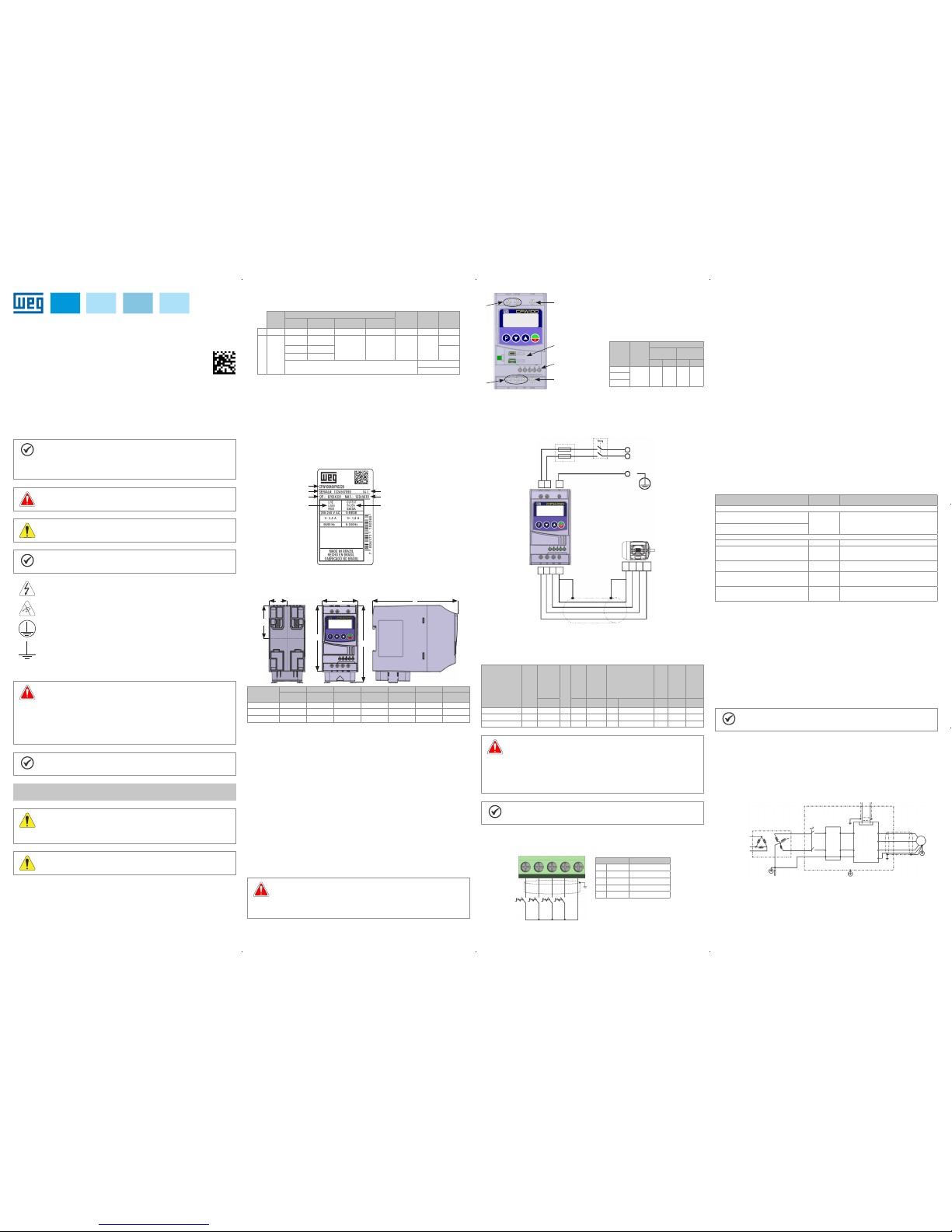
7 IDENTIFICATION LABEL
Production order
Rated input data
(voltage, curren t and
frequency)
Serial number
Manufacturing date (14 corresponds
to the week and I to the year )
Rated output data
(voltage, curren t and frequency)
WEG stock item
Model (Inverte r
intelligent code)
Figure 1: Description of the CFW100 ident ification labe l
8 DIMENSIONS
VIEW OF THE MOUNTI NG BASE
FRONT VIEW
SIDE VIEW
PLB
A
H1
H2
Frame
Size
A B H1 H2 L P Weight
mm
(in)
mm
(in)
mm
(in)
mm
(in)
mm
(in)
mm
(in)
kg
(lb)
A 50 (1.97 ) 28 (1 .10) 100 (3.94) - 5 5 (2 .17) 129 (5.08 ) 0.48 (1. 05)
B 50 (1.97 ) 28 (1.1 0) - 117 (4.6 0) 5 5 (2 .17) 129 ( 5.08 ) 0.57 (1.25)
C 50 (1.97 ) 28 (1.1 0) - 125 .6 (4.9 4) 5 5 (2 .17) 129 (5.08 ) 0.61 (1. 34)
Dimension tolerance: ±1,0 mm (±0,039 in)
Figure 2: Inverter dimensions for mechanical installation
9 INSTALLATION AND CONNECTION
Environmental Conditions
Avoid:
Direct expos ure to sunlight, rain, h igh humidity or s ea-air.
Inflammable or corrosive gases or liquids.
Excessive vibration.
Dust, metalli c particles or oi l mist.
Environment conditions permitted for the operation of the inverter:
Temperature surr ounding the inver ter: 0 ºC to 50 ºC ( 32 ºF to 122 ºF) – I P20.
For temperatur es surroundin g the inverter hig her than the spec ifications above , it is necessar y to apply
of 2 % of current der ating for each degr ee Celsius, limite d to an increase of 10 ºC (50 º F).
Air relative hu midity: 5 % to 95 % non-c ondensing.
Maximum al titude: up to 1000 m (3.300 f t) - rated condition s.
From 1000 m to 4000 m (3.3 00 ft to 13.200 ft) – 1 % of curren t derating for each 100 m above 1000 m
of altitude.
Pollution deg ree: 2 (according to EN5 0178 and UL508C), with non-co nductive pollu tion. Condensa tion
must not originate conduction through the accumulated residues.
10 ELECTRICAL INSTALLATION
DANGER!
The following information is merely a guide for proper installation. Comply with applicable
local regulations for electrical installations.
Make sure the AC power supply is disconnected before starting the installation.
T he CFW100 must not be used as a n emergency stop device . Provide other devices
for that purpose.
1
1
2
2
4
3
1 - Power terminals
2 - Grounding points
3 - Accessory
connectors
4 - Control termina ls
Frame
Size
Power
Supply
Recommended Torque
Grounding
Points
Power
Terminals
N.m Lbf.in N.m Lbf.in
A
200...
240 V
1.4 12.4 1.4 12.4B
C
Figure 3: Power terminals, grounding points and recommended tightening torque
10.1 POWER CONNECTIONS
Descriptio n of the power terminal s:
L/L1 and N/L2 : AC power supply must b e connected to L/ L1 and N/L2.
U, V and W: connection for the motor.
PE: grounding connection.
Shield
PE
PEL2L1
Disconnecting
switch
Fusibles
Power supply
PE W V U
L1/L
L2/N
U V W PE
Figure 4: Power and grounding connections
The CFW100 is suit able for application in a ci rcuit able to supply not more th an 30.000 symetric A
rms
maximum of 240V, when p rotected by fuses cla ssified as indica ted below:
Table 2: List of mode ls of CFW100 series, ma in electrical s pecification s
Inverter
Number of Input
Phases
Power Supply
Rated
Voltage
Frame Size
Output
Rated
Current
Maximum
Motor
Circuit
Breaker
Recommended
J Type Fuse
Power Wire
Size
Grounding
Wire Size
[Vrms] [Arms] [HP/ kW] [A] WEG [A]
mm2
(AWG)
mm2
(AWG)
CFW100A01P6S220 1 200 ... 240 A 1.6 0.25/0.18 5.5 MPW25-3-D063 6 1. 5 (16) 2.5 (14)
CFW100 B02P6 S220 1 2 00 ... 240 B 2.6 0.5/0.37 9.0 MPW25-3-U010 10 1.5 (16 ) 2.5 (14)
CFW100C04P2S220 1 20 0 ... 240 C 4.2 1/0.75 13.5 MPW25-3-U016 17.5 1.5 ( 16) 2.5 (14)
DANGER!
The inverter m ust be connected to a p rotective ground (PE ).
Use a minimum wi re gauge for ground c onnection equa l to the indicated in Table 2.
Connect the inverter grounding connections to a ground bus bar, to a single ground point
or to a common grou nding point (impe dance ≤ 10 Ω).
The neuter con ductor of the line tha t feeds the inverte r must be solidly g rounded; however
this conducto r must not be used to grou nd the inverter.
Do not share the gr ounding wiring with oth er equipment that opera te with high currents
(e.g.: high voltage moto rs, welding machi nes, etc.).
NOTE!
The wire gauge s listed in Table 2 are g uiding valu es. Installa tion conditi ons and the ma ximum
permitted voltage drop must be considered for the proper wiring sizing.
10.2 CONTROL CONNECTIONS
DI11DI2
2
S2S1 S3 S4
DI33DI4
GND
4 5
Connector Description
(**)
1 DI1 Digital input 1
2 DI2 Digital input 2
3 DI3 Digital input 3
(*)
4 DI4 Digital input 4
5 GND Reference 0 V
(*) The digital input 3 (DI3) can also be used as input in fre quency (FI).
Figure 5: Signals of control card co nnector of the C100A-20
For the corr ect connec tion of the con trol, use:
1. Gauge of the cable s: 0.5 mm² (20 AWG) to 1.5 mm² (14 AWG).
2. Maximum torqu e: 0.5 N.m (4.50 lbf.in).
3. Wiring of the co nnector of the control bo ard with shielded ca ble and separated from t he other wiring
(power, command in 110 V / 220 Vac, etc.)
10.3 INSTALLATIONS ACCORDING TO EUROPEAN DIRECTIVE OF ELECTROMAGNETIC
COMPATIBILITY
The CFW100 inver ter series, wh en properly ins talled, meet th e requirements o f the directive of th e
electromagnetic compatibility.
These inverters were developed for professional applications only. Therefore, the emission limits of
harmonic cur rents by the standa rds EN 61000-3-2 and EN 61000 -3-2/A 14.
10.3 .1 Conformal Installation
1. Shielded outpu t cables (motor c ables) with shi eld connecte d at both ends, moto r and inverter, by mea ns
of a low impedanc e to high frequency conn ection. Maximum moto r cable length and cond uced and
radiated emission levels according to Table 5. For more information (RFI filter commercial reference,
motor cable len gth and emission l evels) refer to the Table 5.
2. Shielded control cables, keeping the separation distance from other cables according to Table 3.2 the
user's manual.
3. Grounding of th e inverter acc ording to instr uction of the 3.2.4 Gro unding Conn ections the us er's manual.
4. Grounded powe r supply.
5. The inverter a nd external fil ter must be mounted on a c ommon metal plate.
6. The wiring be tween filter and i nverter must be as s hort as possibl e.
7. The grounding must be done according to recommendation of the CFW100 user's manual.
8. Use short wi ring to ground the exte rnal filter or inve rter.
9. Ground the moun ting plate using a flexible br aid as short as possible. Fl at conductors have lower
impedance at high frequencies.
10. Use sleeves for cable conduits whenever possible.
10.3.2 Emission and Immunity Levels
Table 3: Emission and immunity levels
EMC Phenomenon
Basic
Standard
Level
Emission:
Mains terminal disturbance voltage
Frequency range: 150 kH z to 30 MHz)
IEC/EN 61800-3
It depends on the in verter model on th e length of the
motor cable. Refer to Table 5
Electromagnetic radiation disturbance
Frequency Rang e: 30 MHz to 1000 MHz)
Immunity:
Electrostatic discharge (ESD) IEC 61000-4-2 4 kV fo r contact discha rge and 8 kV for air disc harge
Fast transient-Burst IEC 61000-4-4
2 kV / 5 kHz (coupling ca pacitor) input ca bles
1 kV / 5 kHz control cabl es and remote HMI ca bles
2 kV / 5 kHz (coupling ca pacitor) motor cab les
Imunidade conduzida ("Conducted radiofrequency common mode")
IEC 61000-4-6
0.15 to 80 MHz; 10 V; 80 % AM (1 kHz)
Motor, control and HMI cables
Surges IEC 61000-4-5
1.2/50 μs, 8/20 μs
1 kV line-to-line coupling
2 kV line-to-ground coupling
Radio-frequency electromagnetic field IEC 61000-4-3
80 to 1000 MHz
10 V/m
80 % AM (1 kHz)
Definiti on of Standar d IEC/EM 61800 -3: “Adjusta ble Speed El ectrical Pow er Drives Sys tems”
Environments:
First Environment: environments that include domestic installations, as well as establishments directly
connected without intermediate transformer to a low-voltage power supply network which supplies
buildings used for domestic purposes.
Second Environment: includes all establishments other than those directly connected to a low voltage
power supply network that supplies buildings used for domestic purposes.
Categories:
Category C1: inverters with a vol tage rating le ss than 1000 V and i ntended for us e in the First Env ironment.
Category C2: inverters wit h a voltage rating less t han 1000 V intended for us e in the First Environm ent,
not provided with a plug connector or movable installations. They must be installed and commissioned by
a professional.
NOTE!
A professional is a person or organization familiar with the installation and/or commissioning
of inverters, i ncluding their EM C aspects.
Category C3: inverters w ith a voltage rating le ss than 1000 V and inten ded for use in the Sec ond
Environment only (not designed for use in the First Environment).
10.3.3 Characteri stics of the R FI Filter
The CFW100 inver ters, when installed wit h external filter, are used to reduc e the conducted from the
inverter to the po wer line in the high f requency band (>150). It is neces sary to meet the ma ximum levels of
conducted emission of electromagnetic compatibility standards, such as EN 61800-3 and EN 55011.
For further i nformation abou t the RFI filter model, re fer to Table 4.
The figure below demonstrate the connection of the filter to the inverter:
Protective ground
Metal panel (when necessary)
Grounding
rod
External
input
RFI filter
PE
PE
PE
W
V
U
Signal and control wiring
Transformer
L1/L L1
L1/L
1...5
XC1
PE PE
L2/N L2 L2/N
CFW100
Motor
Power supply
Figure 6: Connection of the RFI fil ter - general con ditions
English
13230 453
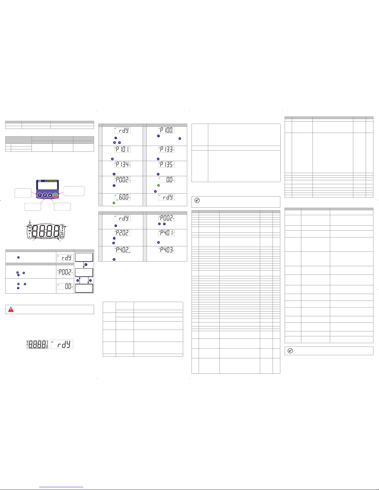
Table 4: Exter nal RFI filter mod els for CFW100
WEG Item Name Description
13128410 CFW100-KFABC External RFI filte r kit WEG
- - Filter B84142A0010R000 Epco s (*)
(*) For Electrodiagnostica Radiation Disturbance use choke (T60006- L2016-W403 – VACUUMSCHMELZE).
Table 5: Conducte d and radiated emis sion levels, and add itional informa tion
Inverter Model
Conducted Emission – Maximum Motor Cable
Length
Radiated Emission
Category C2 Category C3 Category C3
1 CFW100A01P6S220
1 m (39 in) 10 m (393 in) 10 m (393 in)
2 CFW 100B02 P6S220
3 CFW100C04P2S220
(1) The switchi ng frequency is 5 KH z.
10.4 ACCESSORIES
The accesso ries are hardware r esources that ca n be added in the appli cation with the CF W100.
The accesso ries are inco rporated to the inve rters in an ea sy and quick way by us ing the conce pt “Plug and
Play”. The accesso ry must be install ed or modified with the i nverter de-ener gized. They may be orde red
separately, and a re sent in their own package con taining the components an d manuals with detailed
instructions for their installation, operation and setting.
11 USE OF THE K EYPAD TO OPERATE THE INV ERTER
Selects (toggles)
display between th e
parameter number
and its value (position/
content).
Decreases the
frequency, parameter
number or parameter
value.
Increases the
frequency, parameter
number and parameter
value.
Enables/disables the inverter
via acceleration/deceleration
ramp (start/stop, according to
P229). Resets the inver ter after
a fault event.
11.1 INDICATIONS OF DISPLAY
Inverter status
Direction of
rotation
Unit of measurement
(it refers to the valu e
of the main display)
Bar to monitor
the variable
Main display
11.2 OPERATING MODES OF THE HMI
Initialization Mode
It is the initial state o f the HMI after i ts successf ul power-up (with out
the occurrence of faults, alarms or undervoltage).
Press key to go to level 1 o f the parameterization mo de –
selection of par ameters. Pressi ng any other key also sw itches to
parameterization mode.
Monitoring
Parameterization
Level1
Parameterization
Level 2
Parameterization Mode
Level 1:
This is the first le vel of the param eterization m ode. The para meter
number is shown on the main display.
Use keys and to fin d the desired para meter.
Press key to go to level 2 o f the parameterization mo de -
change of the para meter values.
Level 2:
The parameter val ue is shown on the mai n display.
Use keys and to s et the new value in the selected
parameter.
Press key to confi rm the modification (s ave the new value).
After confirm ing the modifi cation, the HMI re turns to level 1 of the
parameterization mode .
Figure 7: HMI operating modes
12 START-UP PREPARATION
DANGER!
Always disconnect the main power supply before making any connection.
1. Check if the power, grounding and control connections are correct and firm.
2. Remove all the mate rials left beh ind from the install ation work from ins ide the inverter or t he cabinet.
3. Verify the moto r connections an d if its voltage and cu rrent are within the i nverter rated valu e.
4. Mechanica lly uncouple the motor from th e load. If the motor cannot be unc oupled, make sure that
any speed dire ction (forward or r everse) will not resu lt in personnel i njury and/or equ ipment damage.
5. Close the inver ter or cabinet cove rs.
6. Measure the po wer supply and ver ify if it is within th e allowed range.
7. Apply power to the input: c lose the input disc onnecting switc h.
8. Check the res ult of the first time p ower-up:
The HMI display indicates:
12.1 BASIC APPLICATION
The following table contains the basic programming to operate the CFW100 via product HMI:
Seq Display Indication/Action Seq Display Indication/Action
1
2
Initialization mode.
Press key to enter the fir st level of the
parameterization mode.
Press keys or to se lect the para meter P100.
Press key if you need to change t he content of
P100 – “Acceleration Tim e” or press key for the
next parameter.
3 4
If necessar y, change the conte nt of “P101 -
Deceleration Time”.
Use key to select the parameter P133.
If necessar y, change the conten t of “P133 - Minimum
Spe ed”.
Press key for the next parameter.
5 6
If necessar y, change the conte nt of “P134 - Maximu m
Spe ed”.
Press key for the next parameter.
If necessar y, change the content of “P135 - Outpu t
Maximum Current”.
Press key to select parameter P 002.
7 8
Press key to view the parameter c ontent.
Press key that the motor will accel erate up to
3.0 Hz (factory defau lt setting of P133 - Minimum
Frequenc y).
Press an d hold it until it reac hes 60.0 Hz.
9 10
Press key . The motor will decel erate to a stop.
When the motor stops, th e display will indicate
“rea dy”.
12.2 TY PE OF CONTROL V/f (P 202 = 0)
Seq Display Indication/Action Seq Display Indication/Action
1
2
Initialization mode.
Press key to enter the fir st level of the
parameterization mode.
Press keys or to se lect parameter P2 02.
3
4
Press key if you need to change t he content of
“P202 – Type of Control” for P2 02 = 0 (V/f).
Press key to select paramete r P401.
If necessary, cha nge the conten t of parameter “P401
– Motor Rated Current ” according to the n ameplate.
Press key for the next parameter.
5
6
If necessar y, change the content of “P402 - Motor
Rated Speed”.
Press key for the next parameter.
If necessar y, change the content of “P403 - Motor
Rated Frequency”.
13 TECHNICAL SPECIFICATIONS
POWE R DATA
Power Supply:
Tolerance: -15 % to +10 %.
Frequency: 50/6 0 Hz (48 Hz to 62 Hz).
Phase imbala nce: ≤ 3 % of the rated phase -to-phase input vol tage.
Overvolta ge according to Categ ory III (EM 61010/UL 508C).
Transient voltages according to Category III.
Maximum of 10 con nections per hou r (1 every 6 minutes).
Typical effic iency: ≥ 97 %.
14 ELECTRONICS/GENERAL DATA
Table 6: Electronics/general data
Control Method Types of control:
- V/f (Scalar)
- VVW: voltage vector control
PWM SVM (Space Vector Modulation)
Output frequency 0 to 300 Hz, res olution of 0.1 Hz
Performance V/f Control Speed reg ulation: 1 % of the rated s peed (with slip co mpensation)
Speed variatio n range: 1:20
Vector control (VVW) Spe ed regulation: 1 % of the r ated speed
Speed variatio n range: 1:30
Inputs Digital 4 isolated inputs
Maximum inpu t voltage of 30 Vdc
Input current: - 11 mA
Maximum inpu t current: -20 mA
Safety Protection Output overcurrent/short-circuit
Under/overvoltage
Motor overload
Overtempera ture in the power modu le (IGBTs)
Fault / external a larm
Programming error
Integral keypad
(HMI)
Standard keypad 4 keys: Start/Stop, Up a rrow, Down arrow and Prog ramming
LCD Display
View/edition of parameters
Indication accuracy:
- current: 5 % of the rated c urrent
- speed resoluti on: 0.1 Hz
Enclosure IP20 Fra me Sizes A, B and C
15 CONSIDERED STANDARDS
Table 7: Considered standards
Safety
standards
UL 508C - power conver sion equipmen t
UL 840 - insulation coordination including clearances and creepage distances for electrical
equipment
EN61800-5-1 - safety requirements electrical, thermal and energy
EN 50178 - electronic equip ment for use in power in stallations
EN 60204-1 - safety of machi nery. Electric al equipment of ma chines. Part 1: gen eral requireme nts
Note: the final assem bler of the machine is re sponsible for insta lling a safety stop dev ice and a
supply disconnecting device
EN 60146 (IEC 146) - semiconducto r converters
EN 61800-2 - adjustabl e speed elec trical power d rive systems - Pa rt 2: genera l requireme nts - rating
specifications for low voltage adjustable frequency AC power drive systems
Mechanical
standards
EN 60529 - degrees of pr otection provide d by enclosures (IP c ode)
UL 50 - enclosures f or electrical eq uipment
Electromagnetic
compatibility
(EMC)
standards
(*)
EN 61800-3 - adjustabl e speed electrical p ower drive systems - part 3: EM C product standard
including specific test methods
EN 55011 - limits and methods of me asurement of radi o disturbance cha racteristics of ind ustrial,
scientific and medical (ISM) radio-frequency equipment
CISPR 11 - industrial, scie ntific and medical ( ISM) radio-frequenc y equipment - electro magnetic
disturbance ch aracteristics - l imits and methods of m easurement
EN 61000-4-2 - electromagnetic compatibility (EMC) - part 4: testing and measurement techniques
- section 2: electrostatic discharge immunity test
EN 61000-4-3 - electr omagnetic co mpatibilit y (EMC) - part 4: test ing and measu rement techn iques
- section 3: radiated, radio-frequency, electromagnetic field immunity test
EN 61000-4-4 - electr omagnetic co mpatibilit y (EMC) - part 4: test ing and measu rement techn iques
- section 4: electrical fast transient/burst immunity test.
EN 61000-4-5 - electr omagnetic co mpatibilit y (EMC) - part 4: tes ting and measu rement techn iques
- section 5: surge imm unity test.
EN 61000-4-6 - elect romagnetic co mpatibilit y (EMC) - part 4: tes ting and measu rement techn iques
- section 6: immuni ty to conducted dis turbances, indu ced by radio-freq uency fields.
(*) Standards met with t he installation of t he external RFI fil ter. For further detai ls refer to www.weg.net.
16 MAIN PAREMETERS
The table bel ow contains the mai ns parameters of the C FW100.
NOTE!
ro = read only para meter.
V/f = parameter avai lable in V/f mode.
cfg = configur ation parameter, value c an only be change d with the motor stoppe d.
Param. Description Adjustable Range Factory Setting Prop.
P000 Access to Parameters 0 to 9999 1
P001 Speed Reference 0 to 9999 ro
P002 Outpu t Speed (Motor) 0 to 9999 ro
P003 Motor Current 0.0 to 10.0 A ro
P004 DC Link Vo ltage (Ud) 0 to 524 V ro
P005 Outpu t Frequency (Motor) 0.0 to 3 00.0 Hz ro
P006 Inverter Statu s 0 = Ready
1 = Run
2 = Undervoltage
3 = Fault
4 = Not Used
5 = Configuration
ro
P007 Output Voltage 0 to 240 V ro
P011 Active Current -10.0 to 10.0 A ro
P012 DI8 to DI1 Status 0 to FF (hexa)
Bit 0 = DI1
Bit 1 = DI2
Bit 2 = DI3
Bit 3 = DI4
Bit 4 = DI5
Bit 5 = DI6
Bit 6 = DI7
Bit 7 = DI8
ro
P022 FI Value in H z 1 to 3000 Hz ro
P023 Main SW Ver sion 0.00 to 99.99 ro
P030 Module Temperature -200.0 to 200.0 ºC ro
P037 Moto r Overload Ixt 0.0 to 100.0 % ro
P047 CONFIG Status 0 to 999 ro
P048 Present Alarm 0 to 999 ro
P049 Present Fault 0 to 999 ro
P050 Last Fa ult 0 to 999 ro
P100 Acceleration Time 0.1 to 999.9 s 5.0
P101 D eceleration Time 0.1 to 999.9 s 10.0
P120 Speed Ref. Backup 0 = Inactive
1 = Active
2 = Backup by P121
1
P121 Reference via HMI 0.0 to 300.0 Hz 3.0 H z
P124 Multispeed Ref. 1 -300.0 to 300.0 Hz 3.0 Hz
P125 Multispeed Ref. 2 -300.0 to 300.0 Hz 10.0 (5.0) Hz
P126 Multispeed Ref. 3 -300.0 to 300.0 Hz 20.0 (10.0) Hz
P127 Multispeed Ref. 4 -300.0 to 300.0 Hz 30.0 (20.0) Hz
P128 Multispeed Ref. 5 -300.0 to 300.0 Hz 40.0 (30.0) Hz
P129 Multispeed Ref. 6 -300.0 to 300.0 Hz 50.0 (40.0) Hz
P130 Multispeed Ref. 7 -300.0 to 300.0 Hz 60.0 (50.0) Hz
P131 Multispeed Ref. 8 -300.0 to 300.0 Hz 66.0 (55.0) Hz
P133 Minimum Frequency 0.0 to 300.0 Hz 3.0 Hz
P134 Maximum Frequency 0.0 to 300.0 Hz 66.0 (55.0) Hz
P135 Maximum Output Current 0.0 to 10.0 A 1.5xI
nom
P136 Manual Torque Boost 0.0 to 30.0 % 0.0 % V/f
P137 Automatic Torque Boost 0.0 to 30.0 % 0.0 % V/f
P138 Slip Compensation -10.0 to 10.0 % 0.0 % V/f
P139 Output Current Filter 0 to 9.999 s 0.005 s
P140 Slip Com. Filter 0 to 9.999 s 0.5 s VVW
P142 Maximum Output Voltage 0.0 to 100.0 % 100 .0 % cf g, V/f
P143 Intermediate Output
Voltage
0.0 to 100.0 % 50.0 % cfg, V/f
P145 Field Weakening Start
Frequency
0.0 to 300.0 Hz 60.0 (50.0) Hz cfg, V/f
P146 Intermediate Frequ ency 0.0 to 30 0.0 Hz 30.0 (25.0) Hz c fg, V/f
P156 Overload Current 0.1 to 2xI
nom
1.2xI
nom
P202 Type of Contr ol 0 = V/f
1 = V/f Quadratic
2 to 4 = Not Used
5 = VV W
0 cfg
P204 Load/Save Parameters 0 to 4 = N ot Used
5 = Load 60 Hz
6 = Load 50 Hz
7 = Load User
8 = Not Used
9 = Save User
10 = Not Used
11 = Load Default SoftPLC
12 to 13 = Reserved
0 cfg
P220 LOC/REM Selection
Source
0 = Always Local
1 = Always Remote
2 to 3 = Not Used
4 = DIx
5 = Serial/USB (LOC )
6 = Serial/USB (R EM)
7 to 8 = Not Used
9 = CO/DN (LOC)
10 = CO/DN (REM)
11 = SoftPLC
0 cfg
P221 LOC Reference Sel. 0 = HMI Keys
1 = AI1
2 to 3 = Not Used
4 = FI
5 to 6 = Not Used
7 = E.P.
8 = Multispeed
9 = Serial/USB
10 = Not Used
11 = CO/DN
12 = SoftPLC
13 = Not Used
14 = AI1 > 0
15 to 16 = Not Used
17 = FI > 0
0 cfg
Param. Description Adjustable Range Factory Setting Prop.
P222 REM Refer ence Sel. See opti ons in P221 2 cfg
P223 LOC Rotation Sel. 0 = Always FWD
1 = Always REV
2 = Not Used
3 = Not Used
4 = DIx
5 = Serial/USB (F WD)
6 = Serial/USB (R EV)
7 to 8 = Not Used
9 = CO/DN (FWD)
10 = CO/DN (REV)
11 = Not Used
12 = SoftPLC
0 cfg
P263 DI1 Input Function 0 = Not Used
1 = Run/Stop
2 = General Enabl e
3 = Quick Stop
4 = Forward Run
5 = Reverse Run
6 = Start
7 = Stop
8 = FWD/REV
9 = LOC/REM
10 = JOG
11 = Increase E.P.
12 = Decelerate E.P.
13 = Multispeed
14 = 2nd Ramp
15 to 17 = Not Used
18 = No Ext. Alarm
19 = No Ext. Fault
20 = Reset
21 to 23 = Not Used
24 = Disab. Flying Star t
25 = Regul. DC Link
26 = Lock Prog.
27 to 31 = Not Used
32 = 2nd Ramp Multispeed
33 = 2nd Ramp E.P. Ac.
34 = 2nd Ramp E.P. De.
35 = 2nd Ramp FRW Run
36 = 2nd Ramp Rev Run
37 = Turn ON / Ac. E.P.
38 = De. E.P. / Turn OFF
39 = Stop
40 = Safety Switch
41 = Function 1 Application
42 = Function 2 Application
43 = Function 3 Application
44 = Function 4 Application
45 = Function 5 Application
46 = Function 6 Application
47 = Function 7 Application
48 = Function 8 Application
1 cfg
P264 DI2 Input Function See options i n P263 8 cfg
P265 DI3 Input Function See opti ons in P263 0 cfg
P266 DI4 Input Function See opti ons in P263 0 cfg
P295 Inv. Rated Cu rrent 1.6 to 15.2 A According to
inverter model
ro
P296 Line Rated Voltage 0 to 1 = Reser ved
2 = 200 - 240 V
2 ro, cfg
P297 Switching Frequency 2.5 to 15.0 kHz 5.0 k Hz
P401 Mo tor Rated Current 0.0 to 10.0 A 1.4 A cfg
P402 M otor Rated Speed 0 to 9999 rpm 1720 (1310) rpm cfg
P403 M otor Rated Frequency 0 to 300 Hz 60 (50 ) Hz cfg
17 FAULTS AND ALARMS
Most common faults and alarms
Fault / Alarm Description Possible Causes
A046
Motor Overload
Motor overload alarm Settin gs of P156 is too low for the used moto r
Overload on the moto r shaft
A050
Power Module
Overtemperature
Overtemperature alarm from the
power module temperature sensor
(NTC)
High temperatur e at IGBTs (P030 > 110 °C)
High ambient tem perature around the inve rter (>50 °C (>
122 °F)) and high output c urrent
Blocked or defec tive fan
Heatsink is too dir ty, preventing the air f low
A090
External Alarm
External ala rm via DIx (option “No
External Ala rm” in P26x)
Wiring on DI1 to DI4 input s are open or have poo r contact
A700
Remote HMI
Communication Fault
No communication with remote HMI,
but here is freque ncy command or
reference for this s ource
Check if the communication interface with the HMI is
properly conf igured in paramete r P312
HMI cable disconnected
F021
Undervoltage on the
DC Link
Undervoltage fault on the intermediate
circuit
Wrong voltage supply; check if the data on the inverter
label comply with the power supply and parameter P296
Supply voltage to o low, producing voltag e on the DC link
below the minimum v alue (in P004):
Ud < 200 Vdc in 200 / 240 Vac
Phase fault in the in put
Fault in the pre-ch arge circuit
F022
Overvoltage on the
DC Link
Overvoltage fault on the intermediate
circuit
Wrong voltage supply; check if the data on the inverter
label comply with the power supply and parameter P296
Supply voltage is too high, producing voltage on the DC
link above the max imum value (in P00 4):
Ud > 410 Vdc in 200 / 240 Vac
Load inertia is to o high or decelera tion ramp is too fast
P151 setting is too high
F031
Fault of
communication with
the accessory
Main control can not establish the
communication link with accessory
Accessory damaged
Poor connection of the accessory
Problem in the iden tificatio n of the access ory; refer to P027
F051
IGBTs
Overtemperatures
Overtemperature fault measured
on the temperature s ensor of the
power pack
High temperatur e at IGBTs (P030 > 120 °C)
High ambient tem perature around the inverte r (>50 °C
(>122 °F)) and high output curre nt
Blocked or defec tive fan
Heatsink is too dir ty, preventing the air f low
F070
Overcurrent/
Shortcircuit
Overcurrent or short-circuit on the
output, DC link or br aking resistor
Short-circuit between two motor phases
IGBTs module in short-circuit or damaged
Start with too sho rt accelerati on ramp
Start with motor spinning without the Flying Start function
F072
Motor Overload
Motor overload faul t
(60 s in 1.5 x Inom)
P156 setting is too low in rel ation to the motor operatin g
current
Overload on the moto r shaft
F080
CPU Fault
(Watchdog)
Fault related to the supervision
algorithm of the in verter main CPU
Electric noise
Inverter firmware fault
F081
Fault on the Save
User function
Fault in the attempt to s ave the user
parameter table
Attempt to save (P204 = 9) mo re than 32 parameters
(with values dif ferent from the fa ctory default) on t he User
parameter table
The function Saves User is blocked
F082
Fault in the Copy
Function (MMF)
Fault in the copy of par ameters Attem pt to copy the parameters fr om the Flash Memory
Module to the inver ter with differe nt software vers ions
F084
Auto-diagnosis
Fault
Fault related to the automatic
identification algorithm of the inverter
hardware
Poor contact in the connection between the main control
anthe power pack
Hardware not compatible with the firmware version
Defect on the inter nal circuits of the inv erter
F091
External Fault
External fau lt via DIx (“No Exte rnal
Fault” in P26x)
Wiring on DI1 to DI4 input s are open or have poo r contact
F701
Remote HMI
communication fault
No communication with the remote
HMI; however, there is com mand or
frequency refe rence for this sourc e
Check that the HMI communication interface is properly
configured in pa rameter P312
HMI cable disconnected
NOTE!
For further information, refer www.weg.net.
Document: 1000 3540581 / 00
 Loading...