

Page 1
Motors I Au tomation I E nergy I Transmissio n & Distribution I C oatings
Frequency Inverter
Convertidor de Frecuencia
Inversor de Frequência
CFW100
User's Manual
Manual del Usuario
Manual do Usuário
Page 2

User's Manual
Manual del Usuario
Manual do Usuário
Series/Série: CFW100
English / Español / Português
Document/Documento: 10001432497 / 02
Models/Modelos: Frame A, B and C
Mec A, B y C
Mec A, B e C
Date/Fecha/Data: 08/2013
Page 3
Summary of Revisions
The information below describes the revisions made to this manual.
English
Revision Description Chapter
00 First edition -
ATTENTION!
Check the frequency of the power sup ply.
In case the power supply frequency is dif ferent from the factory setting (check
P403), it is necessary to set:
P204 = 5 for 60 Hz;
P204 = 6 for 50 Hz.
It is only necessary to set these parameters once.
Refer to the programming manual of the CFW100 for further details about the
programming of parameter P0204.
2 | CFW100
Page 4

Contents
1 SAFETY INSTRUCTIONS ..................................................................................................... 5
1.1 SAFETY WARNINGS IN THE MANUAL ........................................................................ 5
1.2 SAFETY WARNINGS IN THE PRODUCT ...................................................................... 6
1.3 PRELIMINARY RECOMMENDATIONS ........................................................................ 7
2 GENERAL INFORMATION ................................................................................................... 8
2.1 ABOUT THE MANUAL ................................................................................................... 8
2.2 ABOUT THE CFW10 0 ..................................................................................................... 9
2.3 TERMINOLOGY .............................................................................................................11
2.4 IDENTIFICATION LABEL ............................................................................................. 11
2.5 RECEIVING AND STORAGE .........................................................................................12
3 INSTALLATION AND CONNECTION ................................................................................. 13
3.1 MECHANICAL INSTALLATION ....................................................................................13
3.1.1 Environmental Conditions ..................................................................................13
3.1.2 Positioning and Mounting ..................................................................................14
3.1.2.1 Cabinet Mounting ....................................................................................14
3.1.2.2 Sur face Mounting .................................................................................. 15
3.1.2.3 DIN-Rail Mounting ..................................................................................15
3.2 ELECTRICAL INSTALLATION ......................................................................................15
3.2.1 Identification of the Power Terminals and Grounding Points ...................... 15
3.2 .2 Circuit Breakers, Fuses, Grounding and Power ............................................ 16
3.2.3 Power Connections .............................................................................................17
3.2.3.1 Input Connections ..................................................................................18
3.2 .3. 2 Power S upply Reactance ..................................................................... 18
3.2.3.3 Output Connections ............................................................................... 19
3.2.4 Grounding Connections .....................................................................................20
3.2.5 Control Connections ...........................................................................................20
3.2.6 Cable Separation Distance ................................................................................ 22
4 KEYPAD (HMI) AND BASIC PROGRAMMING ..................................................................23
4.1 USE OF THE KEYPAD TO OPER ATE THE INVERTER ............................................... 23
4.2 INDICATIONS ON THE HMI DISPLAY .........................................................................23
4.3 OPERATING MODES OF THE HMI .............................................................................. 24
English
CFW100 | 3
Page 5

Contents
5 FIRST TIME POWER-UP AND START-UP ........................................................................ 26
English
5.1 START-UP PREPARATION ...........................................................................................26
5.2 START-UP ...................................................................................................................... 27
5.2.1 Basic Application .................................................................................................28
5.2.2 V/f Type of Cont rol (P202 = 0) ............................................................................ 29
5.2.3 Control Type V VW (P202 = 5) ............................................................................. 30
6 TROUBLESHOOTING AND MAINTENANCE .................................................................... 32
6.1 FAULTS AND ALARMS .................................................................................................. 32
6.2 SOLUTION FOR THE MOST FREQUENT PROBLEMS .............................................. 32
6.3 INFORMATION NECESSARY FOR CONTACTING TECHNICAL SUPPORT ........... 33
6.4 PREVENTIVE MAINTENANCE ..................................................................................... 33
6.5 CLEANING INSTRUCTIONS ........................................................................................35
7 ACCESSORIES .....................................................................................................................36
8 TECHNICAL SPECIFICATIONS ..........................................................................................37
8.1 POWER DATA ................................................................................................................. 37
8.2 ELECTRONICS/GENE RAL DATA ................................................................................. 37
8.2.1 Considered Standards ........................................................................................38
APPENDIX A - FIGURES ....................................................................................................... 113
APPENDIX B – TECHNICAL ESPECIFICATIONS ............................................................... 115
4 | CFW100
Page 6
Safety Instructions
1 SAFETY INSTRUCTIONS
This manual provides information for the proper installation and operation of the CFW100
frequency inverter.
It has be en written to b e used by qualif ied perso nnel with sui table train ing or technic al qualifi cation
for ope rating this ty pe of equipm ent. The pers onnel shall f ollow all the s afety instru ctions des cribed
in this ma nual and/or de fined by the lo cal regulat ions. Failure to c omply with th e safety inst ructions
may result in death, serious injury, and equipment damage.
1.1 SAFETY WARNINGS IN THE MANUAL
The following safety notices are used in the manual:
DANGER!
The procedures recommended in this warning have the purpose of protecting the
user against death, serious injuries and considerable material damage.
ATTENTION!
The procedures recommended in this warning have the purpose of avoiding
material damage.
NOTE!
The information mentioned in this warning is important for the proper understanding
and good operation of the product.
English
CFW100 | 5
Page 7
Safety Instructions
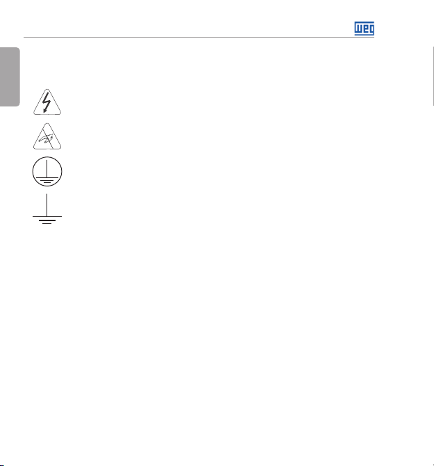
1.2 SAFETY WARNINGS IN THE PRODUCT
English
The following symbols are attached to the product, serving as safety notices:
High voltages are present.
Components sensitive to electrostatic discharge.
Do not touch them.
Mandatory connection to the protective ground (PE).
Connection of the shield to the ground.
6 | CFW100
Page 8
1.3 PRELIMINARY RECOMMENDATIONS
DANGER!
Always disconnect the main power supply before touching any electrical
component associated to the inverter. Several components can remain charged
with high voltages or remain in movement (fans) even af ter the AC power is
disconnected or switched off.
Always connect the grounding point of the inverter to the protection earth (PE).
NOTES!
Frequency Inverter may interfere with other electronic equipment. In order to
reduce these ef fects, take the precautions recommended in the chapter 3 -
Installation and Connections.
Read the user's manual completely before installing or operating the inverter.
Do not perform any withstand voltage test!
If necessary, contact the manufacturer.
ATTENTION!
Electronic boards have components sensitive to electrostatic discharges.
Do not touch directly on components or connectors.
If necessary, first touch the grounding point of the inverter, which must be
connected to the protection earth (PE) or use a proper grounding strap.
Safety Instructions
English
CFW100 | 7
Page 9
General Information
2 GENERAL INFORMATION
English
2.1 ABOUT THE MANUAL
This manual contains information for the proper installation and operation of the inverter,
commissioning, main technical features and how to identify the most usual problems of the
different models of inverters of the CF W100 line.
ATTENTION!
The operation of this equipment requires detailed installation and operation
instructions provided in the user’s manual, programming manual and
communication manuals. The user’s manual is provided in print with the inverter.
The gui des are provid ed in print wit h their respe ctive acces sory. The other m anuals
are provided only electronically in the CD-ROM supplied with the inverter or can
be obtained at WEG website - www.weg.net. The CD-ROM must always be kept
with this equipment. A printed copy of the files available in the CD-ROM can be
requested at your local WEG dealer.
NOTE!
It is not the i ntention of thi s manual to pres ent all the pos sibilitie s for the applic ation
of the CF W100, as well a s WEG cannot tak e any liabilit y for the use of the C FW100
which is not based on this manual.
Part of the figures and tables are available in the annexes, which are divided into annex A for
figures and annex B for technical specifications.
For further information, refer to the programming manual.
8 | CFW100
Page 10

General Information
2.2 ABOUT THE CFW10 0
The CFW100 frequency inverter is a high-performance product which allows speed and torque
control of three-phase induction motors. This product provides the user with the options of vector
(VVW) or scalar (V/f) control, both programmable according to the application.
In the vector mode ( V V W ), the operation is optimized for the motor in use, obtaining a better
performance in terms of speed regulation.
The scalar mode (V/f) is recommended for simpler applications, such as the activation of most
pumps and fans. In such cases it is possible to reduce the losses in the motor and the inverter
using th e “V/f Quadratic”, whic h results in energy savi ngs. The V/f mode is us ed when more than
a motor is activated by an inverter simultaneously (multimotor applications).
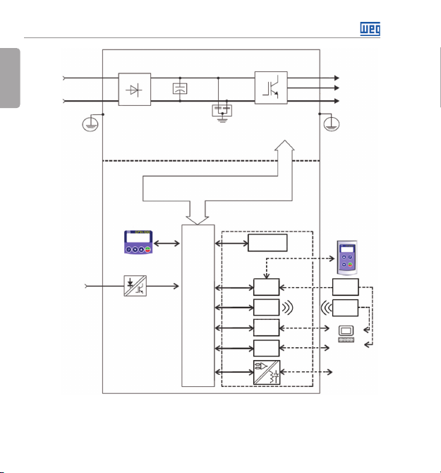
The main components of the CFW100 can be viewed in the block diagram of figure 2.1.
English
CFW100 | 9
Page 11
General Information
English
10 | CF W100
Power
supply
L1/L
L2/N
Digital
inputs
(DI1 to DI4)
PE
Single-phase
rectifier
POWER
CONTROL
Sources for elect ronics and inter faces
HMI
Figure 2.1: CFW100 Block diagr am
bank
Filter
DC link
capacitor
betwee n power and control
Accessories
Flash Memory
Control
board
with CPU
16 bits
Inverter
with IGBT
transistors
Module
RS-485
Bluetooth
USB
Adapter
CANopen/
DeviceNet
U/T1
V/T2
W/T3
PE
(remote)
Converter
USB-RS485
Bluetooth
adapter
(SUPERDRIVE
G2, WLP)
Analog input
Motor
HMI
PC
and relay
output
Page 12
General Information
2.3 TERMINOLOGY
Tab le 2 .1: Termin ology of the CFW100 inver ters
Produ ct
and
Mechanics
Series
Ex.: CFW100 A 01P6 S 2 20 --- ---
A 01P6 = 1.6 A
CFW100
Available options
B 02P6 = 2.6 A
C 04P2 = 4.2 A
20 = IP20
Model Identification
Rated
Current
Number
S = single-phase
Phase
supply
Rated
Volag e
2 = 200...240 V
Degre e of
Protection
Hardware
Software
Versi on
Versi on
Blank =
standard
Sx =
special
software
Blank = standard
Hx = special hardware
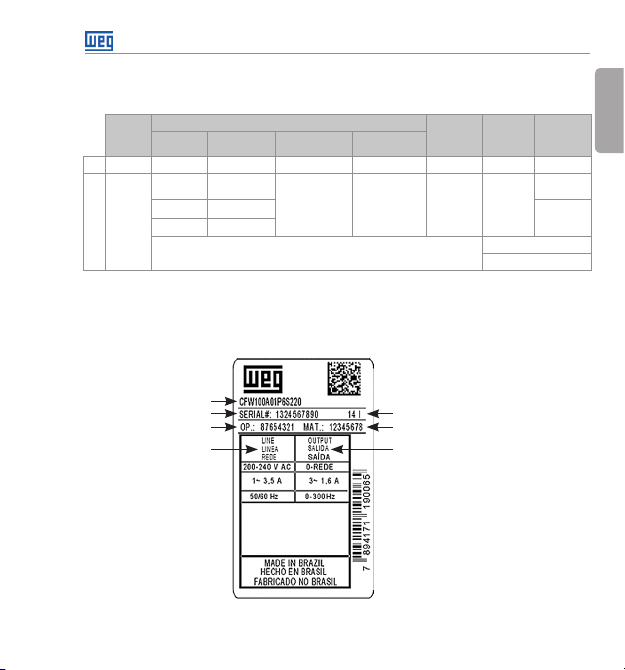
2.4 IDENTIFICATION LABEL
The identification label is located on the side of the inverter. For fur ther details on positioning
the label, refer to figure A2.
English
Model (Inverter
intelligent code)
Serial number
Production order
Rated input data
(voltage, current a nd
frequency)
Manufacturing date (14 corresponds
to the week an d I to the year)
WEG stock Ite m
Rated outp ut data
(voltage, current a nd frequency)
CFW100 Si de Labe l
Figure 2.2: Description of the CFW100 ide ntification label
CFW100 | 11
Page 13
General Information
2.5 RECEIVING AND STORAGE
English
The CF W100 is supp lied packed in a ca rdboard box. There is an id entificati on label aff ixed to the
outside of the package, identical to the one affixed to the side of the inverter.
Verify whether:
The CFW100 identification label corresponds to the purchased model.
Any damage occurred during transportation.
Report any damage immediately to the carrier.
If the CF W100 is not in stalled soo n, store it in a clea n and dry loca tion (temper ature betwee n -25 ºC
and 60 ºC (-13 ºF and 140 ºF)), with a cover to prevent dust accumulation inside it.
ATTENTION!
When the inverter is stored for a long period, it becomes necessary to perform
the capacitor reforming. Refer to the procedure recommended in section 6.4 –
Preventive Maintenance of this manual.
12 | CFW100
Page 14

Installation and Connection
3 INSTALLATION AND CONNECTION
3.1 MECHANICAL INSTALLATION
3.1.1 Environmental Conditions
Avoid:
Direct exposure to sunlight, rain, high humidity or sea-air.
Inflammable or corrosive gases or liquids.
Excessive vibration.
Dust, metallic particles or oil mist.
Environment conditions permitted for the operation of the inverter:
Temperature surrounding the inver ter: 0 ºC to 50 ºC – IP20.
For temperatures surrounding the inverter higher than the specifications above, it is necessary
to apply a 2 % of current derating for each degree Celsius, limited to an increase of 10 ºC.
Air relative humidity: 5 % to 90 % non-condensing.
Maximum altitude: up to 1000 m (3.300 f t) - rated conditions.
From 1000 m to 4000 m (3.30 0 ft to 13.200 ft) – 1 % of current derating for e ach 100 m above
1000 m of altitude.
Pollution degree: 2 (according to EN50178 and UL508C), with non-conductive pollution.
Condensation must not originate conduction through the accumulated residues.
English
CFW100 | 13
Page 15
Installation and Connection
3.1.2 Positioning and Mounting
English
The exte rnal dimen sions and fi xing holes, a nd the invert er net weight (ma ss) are shown in figure B1.
Mount the inverter in the upright position on a flat and ver tical surface. Allow the minimum
clearances indicated in figure B.2 (c), in order to allow the circulation of the cooling air. Do not
install heat sensitive components right above the inverter.
ATTENTION!
When installing two or more inverters vertically, respect the minimum clearance
A + B (as shown i n figure B.2) and provide a n air deflecti ng plate so that the heat
rising up from the lower inverter does not affect the top inverter.
Provide independent conduits for the physical separation of signal, control and
power cables (refer to section 3.2 - Electrical Installation).
3.1.2.1 Cabinet Mounting
For inver ters installed inside cabinets or metallic boxes, provide proper exhaustion, so that
the temperature remains within the allowed range. Refer to the dissipated powers in table B.2.
As a reference, table 3.1 shows the air flow of rated ventilation for each model.
Cooling Method: internal fan with air flow upwards.
Tab le 3 .1: Air flow of the internal fan
Model CFM I/s m3/min
B 6.00 2.83 0.17
C 7. 73 3.65 0.22
14 | CFW100
Page 16
Installation and Connection
3.1.2.2 Sur face Mounting
Figure B.2 (a) illustrates the CFW100 installation procedure for surface mounting, using the
mounting accessory with screws (for further information, refer to chapter 7 – Accessories).
3.1.2.3 DIN-Rail Mounting
The CFW inverter can also be mounted directly on a 35mm-rail, in accordance with DIN EM
50.022. For further details, refer to figure B.2 (b).
3.2 ELECTRICAL INSTALLATION
DANGER!
The following information is merely a guide for proper installation. Comply with
applicable local regulations for electrical installations.
Make sure the AC power supply is disconnected before starting the installation.
The CFW100 must not be used as an emergency stop device. Provide other
devices for that purpose.
3.2.1 Identification of the Power Terminals and Grounding Points
The location of the power, grounding and control connections can be seen in figure B.3.
Description of the power terminals:
L/L1 and N/L2: AC power supply must be connected to L/L1 and N/L2.
U, V and W: connection for the motor.
PE: grounding connection.
The maximum tightening torque of the power terminals and grounding points must be checked
in figure B.3.
English
CFW100 | 15
Page 17
Installation and Connection
3.2 .2 Circuit Breakers, Fuses, Grounding and Power
English
ATTENTION!
Use proper cable lugs for the power and grounding connection cables. Refer to
table B.1 for recommended wiring, circuit breakers and fuses.
Keep se nsitive equ ipment and w iring at a mini mum distan ce of 0.25 m (9.85 in) from
the inverter and from the cables connecting the inverter to the motor.
It is not recommended the use of mini circuit breakers (MDW), because of the
actuation level of the magnet.
ATTENTION!
Residual differential interrupter (DR):
When used in the inverter supply, it must have a pick-up current of 30 0 mA.
Depending on the installation conditions, such as motor cable length and type,
multi-motor drive, etc., the DR interrupter may trip. Check with the manufacturer
the most suitable type for operation with inverters.
NOTE!
The wir e gauges liste d in ta bl e B .1 are guiding values. Installation conditions and the
maximum permitted voltage drop must be considered for the proper wiring sizing.
16 | CFW100
Page 18
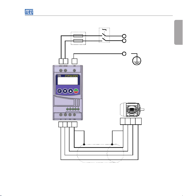
3.2.3 Power Connections
Installation and Connection
Power supp ly
L1/L
Fuse
PEL2L1
Disconnecting
switch
L2/N
PE
English
U V W PE
Shield
Figure 3.1: Power and grounding connections
PE W V U
CFW100 | 17
Page 19
Installation and Connection
3.2.3.1 Input Connections
English
DANGER!
Provide a d isconnect device for the inver ter power supp ly. This dev ice must cut off
the power supply whenever necessar y (during maintenance for instance).
ATTENTION!
The power supply that feeds the inverter must have a grounded neutral.
NOTE!
The input power supply voltage must be compatible with the inverter rated voltage.
Power factor correction capacitors are not needed at the input (L/L1, N/L2) and
must not be installed at the output (U, V, W).
Power supply capacity
The CFW-11 is suitable for use in a circuit capable of delivering not more than 30.000 A
symmetrical (200 to 240 V).
In case the CFW100 is installed in power supplies with current capacity over 30.000 A
it is necessary to use proper protection circuits for those power supplies, such as fuses or
circuit breakers.
3.2 .3. 2 Power S upply Reactance
In a general way, the inverters of the CFW100 line can be installed directly in the power supply,
without reactance in the supply. However, check the following:
In order to prevent damages to the inver ter and assure the expected useful life, you must
have a minimum impedance that provides a line voltage drop of 0.5 %. If the line impedance
(due to the transformers and cabling) is below the values listed in this table, we recommend
the use of a line reactance.
rms
,
rms
18 | CFW100
Page 20
Installation and Connection
For the calculation of the line reactance necessary to obtain the desired percentage voltage
drop, use:
L = 1592 . ΔV .
seeing that:
ΔV - desired line drop, in percentage (%);
V
- phase voltage in the inver ter input, in volts (V);
e
I
- rated current of the inverter input;
e, rat
f - line frequency.
I
V
e, rat
. f
e
[ μH]
3.2.3.3 Output Connections
ATTENTION!
The inverter has an electronic motor overload protection that must be adjusted
according to the driven motor. When several motors are connected to the same
inverter, install individual overload relays for each motor.
The motor overload protection available in the CFW100 is in accordance with
the UL508C standard. Note the following information:
1. Trip current equal to 1.2 times the motor rated current (P401).
2. When parameters P156, P157 and P158 (Overload current at 100 %, 50 %
and 5 % of the rated speed, respectively) are manually set, the maximum
value to meet the condition 1 is 1.1 x P0401.
ATTENTION!
If a disconnect switch or a contactor is installed at the power supply between the
inverter and the motor, never operate it with the motor spinning or with voltage at
the inver ter output.
The characteristics of the cable used to connect the motor to the inverter, as well as its
interconnection and routing, are extremely important to avoid electromagnetic interference in
other equipment and not to affect the life cycle of windings and bearings of the controlled motors.
Keep motor cables away from other cables (signal cables, sensor cables, control cables, etc.),
according to item 3.2.6 - Distance for Cable Separation.
CFW100 | 19
English
Page 21
Installation and Connection
When using shielded cables to install the motor:
English
Follow the recommendations of IEC60034-25.
Use the low impedance connection for high frequencies to connect the cable shield to the
grounding.
3.2.4 Grounding Connections
DANGER!
The inverter must be connected to a protective ground (PE).
Use a min imum wire gau ge for ground c onnectio n equal to the ind icated in table B.1.
Connect the inverter grounding connections to a ground bus bar, to a single
ground point or to a common grounding point (impedance ≤ 10 Ω).
The neu ter conducto r of the line that fe eds the inver ter must be soli dly grounde d;
however, this conductor must not be used to ground the inverter.
Do not share the grounding wiring with other equipment that operate with high
currents (e.g.: high voltage motors, welding machines, etc).
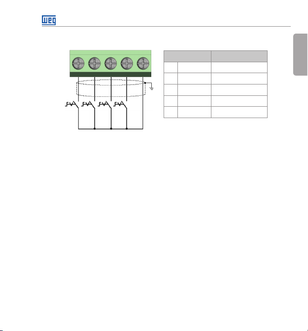
3.2.5 Control Connections
The control connections (digital inputs) must be made in accordance with the specification of
the connector of the CFW100 control board. Functions and typical connections are presented
in figure 3.2. For further details on the specifications of the connector signals, refer to chapter
8 - Technical Specifications.
20 | CFW100
Page 22
Installation and Connection
DI11DI2
(*) The digital input 3 (D I3) can also be used as input in frequenc y (FI). For fur ther details refe r to the progr amming
manual of t he CFW100.
(**) For further information, refer to the detailed specification in section 8.2 - Electronic/General Data.
For the correct connection of the control, use:
1. Gauge of the cables: 0.5 mm² (20 AWG) to 1.5 mm² (14 AWG).
DI33DI4
2
S2S1 S3 S4
Figure 3.2: Signals of control card con nector of the C100A-20
4 5
GND
Connector Description
1 DI1 Digital Input 1
2 DI2 Digital Input 2
3 DI3 Digital I nput 3
4 DI4 Digital Input 4
5 GND Refer ence 0 V
(**)
(*)
2. Maximum torque: 0.5 N.m (4.50 lbf.in).
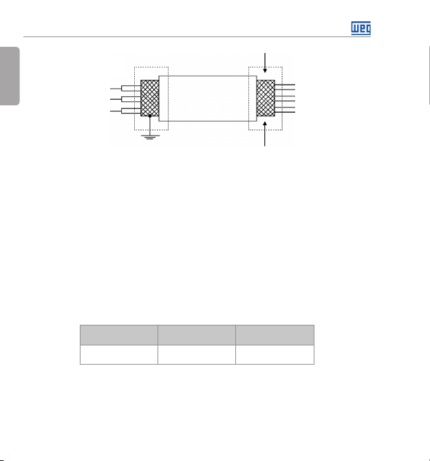
3. Wiring of the connector of the control board wi th shielded ca ble and separated from the other
wiring (power, command in 110 V / 220 Vac, etc), according to item 3.2.6 - Cable Separation
Distance. If those cables must cross other cables, it must be done in perpendicularly among
them, keeping the minimum separation distance of 5 cm at the crossing point. Connect the
shield according to the figure below:
CFW100 | 21
English
Page 23
Installation and Connection
English
4. Relays, contactors, solenoids or coils of electromechanical brake installed close to the inverters
may occasionally generate interference in the control circuitry. To eliminate this effect, RC
suppressors (with AC power supply) or freewheel diodes (with DC power supply) must be
connected in parallel to the coils of these devices.
5. When using the ex ternal HMI (refer to section 7.2 - Accessories), the cable that connects to
the inver ter must be separated from the other cables in the installation, keeping a minimum
distance of 10 cm (3.95 in).
Inverter
side
Figure 3.3: Shield connection
Insulate w ith tape
Do not ground
3.2.6 Cable Separation Distance
Provide separation between the control and the power cables according to table 3.2.
Tab le 3. 2: Separation distance between cables
Output Rated Current
of the In verter
≤ 24 A
Cable Length
≤ 100 m (3937 in)
> 100 m (3937 in)
Minimum Separation
Distance
≥ 10 cm (3.95 in)
≥ 25 cm (9.85)
22 | CFW100
Page 24
Keypad (HMI) and Basic Programming
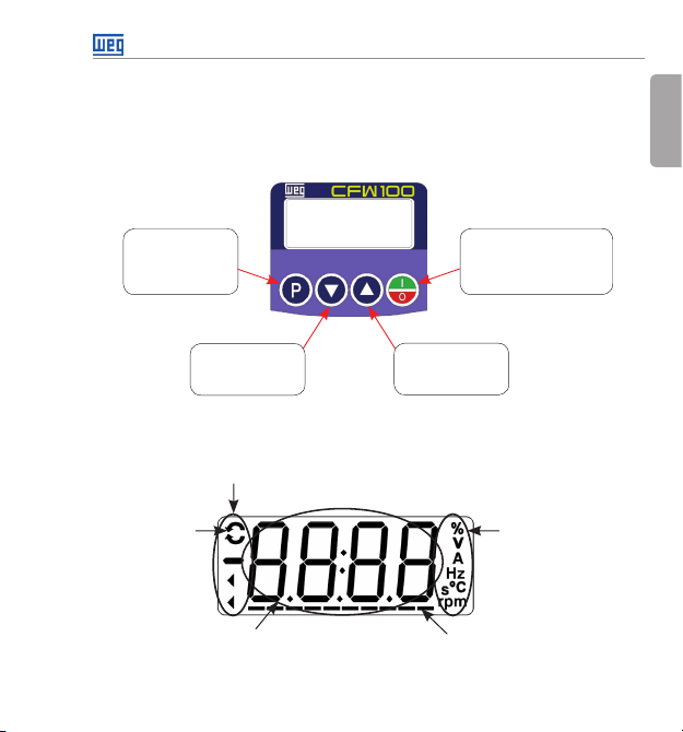
4 KEYPAD (HMI) AND BASIC PROGRAMMING
4.1 USE OF THE KEYPAD TO OPER ATE THE INVERTER
Throu gh the HMI, it is pos sible to comma nd the inverte r, visuali ze and adjust al l of its paramete rs.
The Keypad features the following functions:
English
Selects (toggles)
display be tween the
parameter number
and its value (position/
content).
Decreases the
frequen cy, parameter
number or parameter
value.
Figure 4.1: HMI keys
4.2 INDICATIONS ON THE HMI DISPLAY
Inverter status
Directi on of
rotation
Main display
Figure 4.2: Display areas
Enables/disables the inverter via
acceleration/deceleration ramp
(start/stop, according to P229).
Resets the i nverter after a fa ult
event.
Increas es the
frequen cy, parameter
number an d parameter
value.
Bar to monitor
the variable
Unit of measurement
(it refer s to the value
of the main display)
CFW100 | 23
Page 25
Keypad (HMI) and Basic Programming
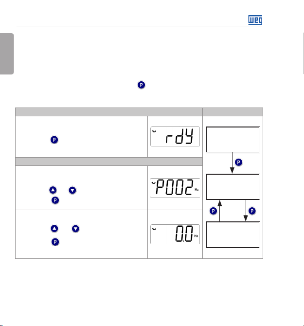
4.3 OPERATING MODES OF THE HMI
English
When energizing the inverter, the initial state of the keypad remains in the start-up mode as long
as there is no fault, alarm, undervoltage or any key is pressed.
The parameterization mode is composed of two levels: level 1 allows the navig ation through the
parameters. And level 2 allows the edition of the parameter selected at level 1. At the end of this
level the modified value is saved when the key is pressed.
Figure 4.3 illustrates the basic navigation of the operating modes of the HMI.
It is the ini tial state of the HMI af ter its successfu l
power-up (without the occurrence of faults, alarms or
undervoltage).
Press key to go to level 1 of the para meterization
mode – sel ection of para meters. Pres sing any othe r key
also switc hes to parameterization mo de.
Level 1:
This is the f irst leve l of the para meteriz ation mod e.
The parameter number is shown on the main display.
Use keys and to find the d esired paramete r.
Press key to go to lev el 2 of the parameter ization
mode – cha nge of the parameter values.
Level 2:
O The para meter value is shown o n the main display.
Use keys and to set the new value in th e
selected parameter.
Press key to conf irm the mo dification (save th e
new value). Af ter confirmin g the modificati on, the HMI
returns to level 1 of the pa rameterization m ode.
Initialization Mode
Parameterization Mode
Figure 4.3: HMI operating modes
Monitoring
Parameterization
Level 1
Parameterization
Level 2
24 | CFW100
Page 26
Keypad (HMI) and Basic Programming
NOTE!
When the inverter is in the fault state, the main display indicates the number of
the fault in the format Fxxx. Navigation is allowed after activation of key .
NOTE!
When the inverter is in the alarm state, the main display indicates the number of
the alarm in the format Axxx. The navigation is allowed after the activation of key
; thus, the indication “A” goes to the unit of measurement display until the
situation causing the alarm is solved.
NOTE!
A list of pa rameters is p resented in th e quick refer ence of the par ameters. For f urther
information about each parameter, refer to the CFW100 programming manual.
English
CFW100 | 25
Page 27
First Time Power-Up and Start-Up
5 FIRST TIME POWER-UP AND START-UP
English
5.1 START-UP PREPARATION
The inve rter must hav e already be en installe d according to chapter 3 - Installation and Connection.
DANGER!
Always disconnect the main power supply before making any connection.
1. Check if the power, grounding and control connections are correct and firm.
2. Remove all the materials left behind from the installation work from inside the inverter or the
cabinet.
3. Verify the motor connections and if its voltage and current are within the inver ter rated value.
4. Mechanically uncouple the motor from the load. If the motor cannot be uncoupled, make
sure that any speed direction (for ward or reverse) will not result in personnel injury and/or
equipment damage.
5. Close the inverter or cabinet covers.
6. Measure the power supply and verify if it is within the allowed range, according to chapter
8 - Technical Specifications.
7. Apply power to the input: close the input disconnecting switch.
8. Check the result of the first time power-up:
26 | CFW100
Page 28
First Time Power-Up and Start-Up
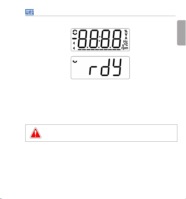
The HMI display indicates:
Figure 5.1: HMI Display when p owering up
5.2 START-UP
This section describes the power-up of the inverter with HMI operation, using the minimum
connections of figure 3.1 and without connections in the control terminals. Furthermore, two types
of control will be considered: V/f control (scalar) and vector control V VW. For further details on
the utilization of these types of control refer to the CFW100 programming manual.
DANGER!
High voltages can be present, even after the disconnection of the power supply.
Wait at least 10 minutes for full discharge.
English
CFW100 | 27
Page 29
First Time Power-Up and Start-Up
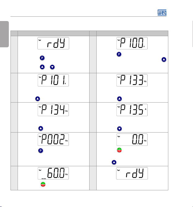
5.2.1 Basic Application
English
Seq Display Indication/Action Seq Display Indication/Action
Initialization Mode.
1
Press key to enter the first level of the
parameterization mode.
Press keys or to selec t the parameter
P100.
3 4
If neces sary, change the co ntent of
“P101 – Deceleration Time”.
Use key até selec ionar o parâmet ro P133.
5 6
If neces sary, change the co ntent of
“P134 – Maxim um Speed”.
Press key for the next parameter.
7 8
Press key to view t he parameter conte nt.
9 10
Press key . The m otor will de celerate
to a stop.
28 | CFW100
Figure 5.2: Sequence for basic application
2
Press key if you n eed to change th e content
of P100 – “Accelera tion Time” or pres s key
for the next parameter.
If neces sary, change the co ntent of
“P133 – Minimum Speed”.
Press key for the next parameter.
If neces sary, change the co ntent of
“P135 – Output Maximum Current ”.
Press key to sele ct parameter P002.
Press key that the m otor will acceler ate up
to 3.0 Hz (factor y default setting of
P133 – Minimum Fre quency).
Press an d hold it until it reac hes 60.0 Hz.
When the motor stops, the display w ill indic ate
“r eady ”.
Page 30
First Time Power-Up and Start-Up
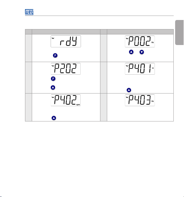
5.2.2 V/f Type of Cont rol (P202 = 0)
Seq Display Indication/Action Seq Display Indication/Action
1
Initialization mode.
Press key to enter the first level of the
parameterization mode.
2
Press keys or to select parameter
P202.
English
3
Press key if you n eed to change th e content
of “P202 – Type of con trol” for P202 = 0 (V/f).
Press ke y to select par ameter P401.
5
If neces sary, change the co ntent of
“P402 - Motor Rate d Speed”.
Press key for the next parameter.
Figure 5.3: Sequence for V/f control
4
If neces sary, change t he content of par ameter
“P401 – Motor Rated C urrent ” accordi ng to
the nameplate.
Press key for the next parameter.
6
If neces sary, change the co ntent of
“P403 – Motor Rate d Frequency”.
CFW100 | 29
Page 31

First Time Power-Up and Start-Up
5.2.3 Control Type V VW (P202 = 5)
English
Seq Display Indication/Action Seq Display Indication/Action
1
Initialization Mode.
Press key to enter the first level of the
parameterization mode.
3 4
Press key to c hange the content of
“P202 – Type of control” for P202 = 5 (V V W).
Use key .
5 6
If neces sary, change the co ntent of
“P399 – Moto r rated eff icien cy” according to
the nameplate.
Press key for the next parameter.
7 8
If neces sary, change the co ntent of
“P401 - Motor rated current”.
Press key for the next parameter.
Figure 5.4: Sequence for VV W control
30 | CFW100
2
Press keys or to select parameter
P202.
Press key to save th e change of P202.
Use key to select parameter P399.
If neces sary, change the co ntent of
“P400 – Motor Ra ted Voltage”.
Press key for the next parameter.
If neces sary, change the co ntent of
“P402 – Motor Rate d Speed”.
Press key for the next parameter.
Page 32

First Time Power-Up and Start-Up
Seq Display Indication/Action Seq Display Indication/Action
9 10
If neces sary, change the co ntent of
“P403 – Motor Rate d Frequency”.
Press key for the next parameter.
11 12
If neces sary, change the co ntent of
“P407 – Motor rated p ower factor ”.
Press key for the next parameter.
Figura 5 .4 (cont.): Sequence for VV W control
If neces sary, change the co ntent of
“P404 – Motor rate d power”.
Press key for the next parameter.
If neces sary, change the co ntent of
“P409 - Stator R esistance”.
CFW100 | 31
English
Page 33

Troubleshooting and Maintenance
6 TROUBLESHOOTING AND MAINTENANCE
English
6.1 FAULTS AND ALARMS
NOTE!
Refer to the CFW100 quick reference and the programming manual for further
information on each fault or alarm.
6.2 SOLUTION FOR THE MOST FREQUENT PROBLEMS
Tab le 6 .1: Solution fo r the most fre quent problems
Problem Point to be Verified Corrective Action
Motor will n ot start Incorrect wiring 1. Check all power and control connections.
Motor speed
oscillates
Too high or too low
motor speed
Display i s off Keypad Connections 1. Check the inverter keypad connection.
Incorrect settings 1. Check if the pa rameter valu es are correc t for the applic ation.
Fault 1. Check wheth er the inverter is disabled d ue to a fault
Motor stall 1. Decrease th e motor overload.
Loose connections 1. Stop the inver ter, turn off the p ower supply, che ck and tighten
Incorrect settings
(reference limits)
Motor nameplate 1. Check whether the used motor matches the application.
Power supply voltage 1. Rated value s must be within the li mits specified below:
Mains supply fuses open 1. Replace the fuses.
condition.
2. Increase P136, P137 (V/f).
all the power connections.
2. Check all the internal connections of the inverter.
1. Check wheth er the values of P0133 (minim um speed) and
P0134 (maximum speed ) are prope rly set for the used
motor and application.
200-240 V power supply: - Minimum: 170 V
Maxim um: 264 V.
32 | CFW100
Page 34

Troubleshooting and Maintenance
6.3 INFORMATION NECESSARY FOR CONTACTING TECHNICAL SUPPORT
For technical support or ser vicing, it is important to have the following information in hand:
Inverter model.
Seria l number and m anufactur ing date liste d in the product n ameplate (re fer to 2.4 - Identifi cation
Labels).
Installed Sof tware version (refer to P023).
Data on the application and inver ter settings.
6.4 PREVENTIVE MAINTENANCE
DANGER!
Always turn off the mains power supply before touching any electrical component
associated to the inverter.
High voltages may still be present even after disconnecting the power supply.
To prevent electric shock, wait at least ten minutes after turning off the input
power for the complete discharge of the power capacitors. Always connect the
equipment frame to the protective ground (PE). Use the adequate connection
terminal at the inverter.
ATTENTION!
The electronic boards have electrostatic discharge sensitive components.
Do not touch the components or connectors directly. If necessary, first touch the
grounded metallic frame or wear a ground strap.
Do not perform any withstand voltage test: If necessar y, consult WEG.
English
CFW100 | 33
Page 35

Troubleshooting and Maintenance
The inverters require low maintenance when properly installed and operated.
English
Table 6.2 presents the main procedures and time intervals for preventive maintenance. Table 6.3
provides recommended periodic inspections to be performed every 6 months after the inverter
start-up.
Tab le 6. 2: Preventive maintenance
Maintenance Interval Instructions
Fan replacement After 40000 operating hours. Replacement
Electrolytic
capacitors
Fans / Cool ing systems
Printed circuits boards
Power modu le / Power
connections
DC bus capacitors
(Dc link)
Power resi stors
Heatsink
(*) The CFW100 fan can be eas ily replaced as shown in figure 6.1.
34 | CFW100
If the inver ter
is stocked
(not being
used ):
“Reforming”
Inverte r is
being us ed:
replace
Component Abnormality Corrective Action
Terminals, connectors
Every year from the manufacturing
date printe d on the inverter
identifi cation label (refe r to section
2.5 - Receiv ing and Storage).
Every 10 years.
Tab le 6. 3: Recomm ended pe riodic inspections – ever y 6 months
Loose screws
Loose connectors
Dirty fans Clean
Abnormal acoustic noise Replace the fan
(*)
Blocked fan
Dust in the c abinet air filter
Accumulation of dust, oil, humidity, etc. Clean
Odor Replace
Accumulation of dust, oil, humidity, etc. Clean
Loose connections screws Tighten
Discoloration / odor / electrolyte leakage
Frame expansion
Discoloration
Odor
Accumulation of dust.
Dirt
Apply po wer to the inverter (vo ltage between
220 and 230 Vac, si ngle-phase, 50 o r 60 Hz) for
at least one hour. Then, disconnect the power
supply a nd wait at least 24 hour s before using
the inver ter (reapply powe r).
Contact W EG technical supp ort to obtain
replacement procedures.
Tighten
Clean or replaceAbnormal vibration
ReplaceExpan ded or broken safet y valve
Replace
Clean
Page 36

Troubleshooting and Maintenance
6.5 CLEANING INSTRUCTIONS
When it is necessary to clean the inver ter, follow the instructions below:
Ventilation system:
Disconnect the inverter power supply and wait for 10 minutes.
Remove the dust from the cooling air inlet by using a sof t brush or cloth.
Remove the dust from the heatsink fins and from the fan blades by using compressed air.
1 2
3
English
Local ization of th e fan
in the produc t
remove t he fan
Figure 6.1: Removal of the heat sink fans
Cable disconnectionRelea se the latche s to
CFW100 | 35
Page 37

Accessories
7 ACCESSORIES
English
The accessories are hardware resources that can be added to the application. Thus, all models
can receive all the presented options.
The acc essories a re installe d in the invert ers easily a nd quickly u sing the “Plug a nd Play” conc ept.
The accessor y must be installed or modified with the inverter power supply off. They may be
ordered separately, and will be shipped in individual packages containing the components and
the manuals with detailed instructions for the product installation, operation and programming.
Tab le 7.1: Accessory models
WEG Item Name Description
11710 62 6 CFW100-CRS485 RS485 Communication Module
1172 275 3 CFW100-CUSB USB Communication Module (2 m cable attached)
1229 3350 CFW100-IOAR Input and output ex pansion module: 1 an alog input and 1 rel ay output
12293349 CFW100-CCAN CANOpen communication module
1229 3257 CFW100-CBLT Bluetooth communication module
11710 65 2 CFW100-MMF Flash memory module (3 m cable attached)
11710 65 0 CFW100-KHMIR CFW100 rem ote HMI kit (CFW100-C RS485 + 3 m cable attached)
10185925 PLMP PLMP Adapter kit for mounting with screws (set with 2 unities)
Control accessories
Flash memory module
Exte rnal keypad
Miscellaneous
36 | CFW100
Page 38

Technical Specifications
8 TECHNICAL SPECIFICATIONS
8.1 POWER DATA
Power Supply:
Tolerance: -15 % to +10 %.
Frequency: 50/60 Hz (48 Hz to 62 Hz)
Phase imbalance: ≤ 3 % of the rated phase-to-phase input voltage.
Overvoltage according to Category III (EM 61010/UL 508C).
Transient voltages according to Category III.
Maximum of 10 connections per hour (1 every 6 minutes).
Typical efficiency: ≥ 97 %.
For further information about the technical specifications, refer to annex B.
8.2 ELECTRONICS/GENE RAL DATA
Tab le 8 .1: Electronics/General Data
CONTROL METHOD Types of contro l:
PERFORMANCE V/f CONTROL Speed regu lation: 1 % of the rated sp eed (with slip
INPUTS DIGITAL 4 isolated inputs.
SAFETY PROTE CTION Output overcurrent/short-circuit.
OUTPUT FREQUENCY 0 to 300 Hz, reso lution of 0.1 Hz.
VECTOR CONTROL
(VV W)
- V/f (Scalar);
- VV W: voltage vector control.
PWM SVM (Space Vector Modulation)
compensation).
Speed va riation r ange: 1:20.
Speed re gulation: 1 % of the rated s peed.
Speed va riation r ange: 1:30.
Maxim um input voltage of 3 0 Vdc.
Input current: - 11mA.
Maximum input current: -20mA.
Under/overvoltage.
Motor overload.
Overte mperature in the power module (IGBTs).
Fault / exte rnal alarm.
Programming error.
English
CFW100 | 37
Page 39

Technical Specifications
English
INTEGRAL
KE YPAD (HMI)
ENCLOSURE IP20 Frames A , B and C.
STANDARD KEYPAD 4 keys: Start/Stop, Up ar row, Down arrow and Programming.
Table 8.1 (cont.): Electronics/General Data
LCD Display.
View/edition of parameters.
Indication accuracy:
- current: 5 % of the rated cu rrent;
- speed re solution: 0.1 Hz.
8.2.1 Considered Standards
Tab le 8. 2: Considered standards
SAFET Y
STANDARDS
MECHANICAL
STANDARDS
UL 508C - Power convers ion equipment.
UL 840 - Insu lation coordin ation including c learances an d creepage dista nces for electri cal
equipment.
EN61800-5-1 - Safety requirements electrical, thermal and energy.
EN 50178 - Electronic e quipment for use i n power installati ons.
EN 60204-1 - Safet y of machin er y. Electri cal equi pment of machines. Part 1: general
requirements.
Note: The final assemble r of the machine is resp onsibl e for insta lling a saf ety stop device
and a supply disconnecting device.
EN 60146 (IEC 146) - Semico nductor conver ters.
EN 61800-2 - Adjus table spee d electrica l power drive sy stems - Part 2: Gen eral requir ements
Rating sp ecifications for low volta ge adjustable frequency AC power drive systems.
EN 60529 - Deg rees of protection provided by e nclosures (IP co de).
UL 50 - Enclo sures for electr ical equ ipment.
38 | CFW100
Page 40

Sumario de las Revisiones
La información a seguir describe las revisiones llevadas a cabo en este manual.
Revisión Descripción Capítulo
00 Primera edición -
¡ATENCIÓN!
Verificar la frecuencia de la red de alimentación.
En caso de que la frecuencia de la rede de alimentación sea diferente del ajuste
de fábrica (verificar P403) será necesario programar:
P204 = 5 para 60 Hz;
P204 = 6 para 50 Hz.
Solamente será necesario efectuar esa programación una vez.
Consulte el manual de programación del CFW100 para más detalles sobre la
programación del parámetro P204.
Español
CFW100 | 39
Page 41

Índice
1 INSTRUCCIONES DE SEGURIDAD ................................................................................... 42
1.1 AVISOS DE SEGURIDAD EN EL M ANUAL .................................................................. 42
1.2 AVISOS DE SEGURIDAD EN EL PRODUCTO ............................................................ 43
1.3 RECOMENDACIONES PRELIMINARES .....................................................................44
2 INFORMACIONES GENERALES ........................................................................................45
2.1 SOBRE EL MANUAL ..................................................................................................... 45
2.2 SOBRE EL CFW10 0 ....................................................................................................... 46
2.3 NOMENCLATURA .........................................................................................................48
Español
2.4 ETIQUETA DE IDENTIFICACIÓN .................................................................................48
2.5 RECEPCIÓN Y ALMACENAMIENTO...........................................................................49
3 INSTALACIÓN Y CONEXIÓN ..............................................................................................50
3.1 INSTALACIÓN MECÁNICA ...........................................................................................50
3.1.1 Condiciones Ambientales ...................................................................................50
3.1.2 Posicionamiento y Fijación ................................................................................51
3.1.2.1 Montaje en Tablero ................................................................................. 51
3.1.2.2 Mont aje en Superficie ............................................................................ 52
3.1.2.3 Montaje en Riel DIN ................................................................................ 52
3.2 INSTALACIÓN ELÉCTRICA ..........................................................................................52
3.2 .1 Ident ificación de los Bornes de Potencia y Puntos de Puesta a Tierra ...... 52
3.2 .2 Cableado de Potencia, Puesta a tierra, Disyuntores y Fusibles .................. 53
3.2 .3 Conexiones de Potencia ..................................................................................... 54
3.2.3.1 Conexiones de Entrada ..........................................................................55
3.2 .3. 2 Reac tancia de la Red ............................................................................. 56
3.2.3.3 Conexiones de Salida ............................................................................ 56
3.2 .4 Conexiones de Puesta a Tier ra ......................................................................... 57
3.2.5 Conexiones de Control .......................................................................................58
3.2 .6 Distancia para Separación de Cables .............................................................. 59
4 HMI Y PROGRAMACIÓN BÁSICA ..................................................................................... 60
4.1 USO DE LA HMI PARA OPERACIÓN DEL CONVERTIDOR ...................................... 60
4.2 INDICACIONES EN EL DISPLAY DE L A HMI ............................................................. 60
4.3 MODOS DE OPERACIÓN DE LA HMI ......................................................................... 61
40 | CFW100
Page 42

Índice
5 ENERGIZACIÓN Y PUESTA EN FUNCIONAMIENTO ...................................................... 63
5.1 PREPARACIÓN Y ENERGIZACIÓN ............................................................................. 63
5.2 PUESTA EN FUNCIONAMIENTO .................................................................................64
5.2.1 Aplicación Básica ................................................................................................65
5.2.2 Tipo de Control V/f (P202 = 0) ............................................................................ 66
5.2.3 Tipo de Control VV W (P202 = 5) ........................................................................ 67
6 DIAGNÓSTICO DE PROBLEMAS Y MANTE NIMIENTO .................................................. 69
6.1 FALLAS Y ALARMAS ..................................................................................................... 69
6.2 SOLUCIÓN DE LOS PROBLEM AS MÁS FRECUENTES ........................................... 69
6.3 DATOS PARA CONTACTO CON LA ASISTENCIA TÉCNICA ................................... 70
6.4 MANTENIMIENTO PREVENTIVO ................................................................................ 70
6.5 INSTRUCCIONES DE LIMPIEZ A ................................................................................ 72
7 ACCESORIOS .......................................................................................................................73
8 ESPECIFICACIONES TÉCNICAS .......................................................................................74
8.1 DATOS DE POTENCIA ................................................................................................... 74
8.2 DATOS DE LA ELECTRÓNICA/GENERALES ............................................................. 74
8.2.1 Normas Consideradas ........................................................................................75
ANEXO A - FIGURAS ............................................................................................................. 113
ANEXO B – ESPECIFICACIONES TÉCNICAS ..................................................................... 115
Español
CFW100 | 41
Page 43

Instrucciones de Seguridad
1 INSTRUCCIONES DE SEGURIDAD
Este manual contiene las informaciones necesarias para el uso correcto del convertidor de
frecuencia CFW100.
El mismo f ue desarro llado para se r utilizado po r personas co n capacitac ión o califi cación técni ca
adecuadas para operar este tipo de equipo. Estas personas deben seguir las instrucciones de
seguridad definidas por las normas locales. No seguir las instrucciones de seguridad puede
derivar en riesgo de muerte y/o daños en el equipo.
Español
1.1 AVISOS DE SEGURIDAD EN EL M ANUAL
En este manual son utilizados los siguientes avisos de seguridad:
¡PELIGRO!
Los proc edimientos re comendados e n este aviso tien en como objeti vo proteger al
usuario contra muerte, heridas graves y daños materiales considerables.
¡ATENCIÓN!
Los procedimientos recomendados en este aviso tienen como objetivo evitar
daños materiales.
¡NOTA!
Las informaciones mencionadas en este aviso son importantes para el correcto
entendimento y bom funcionamiento del producto.
42 | CFW100
Page 44

Instrucciones de Seguridad
1.2 AVISOS DE SEGURIDAD EN EL PRODUCTO
Los siguientes símbolos están pegados al producto, sirviendo como aviso de seguridad::
Tensiones elevadas presentes.
Componentes sensibles a descarga electrostática.
No tocarlos.
Conexión obligatoria a la tierra de protección (PE).
Conexión del blindaje a la tierra.
Español
CFW100 | 43
Page 45

Instrucciones de Seguridad
1.3 RECOMENDACIONES PRELIMINARES
¡PELIGRO!
Desconecte siempre la alimentación general antes de tocar cualquier componente
eléctrico asociado al convertidor. Muchos componentes pueden permanecer
cargados con altas tensiones y/o en movimiento (ventiladores), incluso después de
que la entrada de alimentación CA haya sido desconectada o apagada. Aguarde
por lo menos 10 minutos para garantizar la total descarga de los condensadores.
Español
Siemp re conecte el p unto de puesta a t ierra del co nvertido r a tierra de prote cción (PE).
¡NOTAS!
Los convertidores de frecuencia pueden interferir en otros equipos electrónicos.
Siga los cuidados recomendados en el capítulo 3 - Instalación y Conexión, para
minimizar estos efectos.
Lea completamente este manual antes de instalar u operar este convertidor
No ejecute ningún ensayo de tensión a plicada en el convertidor.
En caso de que sea necesario, consulte al fabricante.
¡ATENCIÓN!
Las tarjetas electrónicas poseen componentes sensibles a descarga electrostática.
No toque directamente los componentes o conectores. En caso de que sea
neces ario, toque an tes el punto de pue sta a tierra de l convertid or, el que debe est ar
conec tado a tierra d e protección (PE ) o utilice pul sera de puest a a tierra adec uada.
44 | CFW100
Page 46

Informaciones Generales
2 INFORMACIONES GENERALES
2.1 SOBRE EL MANUAL
Este manual presenta informaciones para la adecuada instalación y operación del convertidor,
puesta en funcionamiento, principales características técnicas y de cómo identificar y corregir
los problemas más comunes de los diversos modelos de convertidores de la línea CFW100.
¡ATENCIÓN!
La operación de este equipo requiere instrucciones de instalación y de operación
detalladas, suministradas en el manual del usuario, manual de programación y
manuales de comunicación. El manual del usuario es suministrado impreso con
el convertidor. Las guías son suministradas impresas con su respectivo accesorio.
Los demás manuales son suministrados solamente en formato electrónico en
CD-ROM que viene con el convertidor, o pueden ser obtenidos en el sitio web
de WEG - www.weg.net. El CD-ROM deberá ser siempre mantenido con este
equipo. Puede ser solicitada una copia impresa de los archivos presentes en el
CD-ROM por medio de su representante local WEG.
¡NOTA!
No es la intención de este manual agotar todas las posibilidades de aplicación
del CFW100, ni la WEG puede asumir ninguna responsabilidad por el uso del
CFW100 que no esté basado en este manual.
Parte de las figuras y de las tablas están a disposición en los anexos, los cuales se dividen en
anexo A para figuras y anexo B para especificaciones técnicas.
Para más informaciones, consultar el manual de programación.
Español
CFW100 | 45
Page 47

Informaciones Generales
2.2 SOBRE EL CFW10 0
El conve rtidor de fre cuencia CF W100 es un pro ducto de alta pe rformanc e que permite el c ontrol
de velocidad y de torque de motores de inducción trifásicos. Este producto proporciona al usuario
las opciones de control vectorial (VVW ) o escalar (V/f), ambos programables de acuerdo a la
aplicación.
En el modo vectorial (V VW ) la operación es optimizada para el motor en uso, obteniéndose
un mejor desempeño en términos de regulación de velocidad.
Español
El modo escalar (V/f) es recomendado para aplicaciones más simples como el accionamiento
de la mayoría de las bombas y ventiladores. En esos casos es posible reducir las pérdidas en el
motor y en el c onvertid or, utiliz ando la opció n “V/f Cuadrátic a”, lo que res ulta en ahorr o de energía.
El modo V/f también es utilizado cuando es accionado más de un motor, por un convertidor
simultáneamente (aplicaciones multimotores).
Los principales componentes del CFW100 pueden ser visualizados en el diagrama de bloques
de la figura 2.1.
46 | CFW100
Page 48

Informaciones Generales
Red de
alimentación
L1/L
L2/N
Entradas
digitales
(DI1 a DI4)
Rectificador
monofásico
PE
POTÊNCIA
CONTROL
Banco de
Fuentes pa ra electrónica e interfaces entre
HMI
Figura 2.1: Diagrama de bloques del CFW100
Filtro
enlace C C
condensadores
potencia y control
Tar jet a de
control
con CPU
16 bits
Convertidor
con transistores
IGBT
Accesorios
Módulo de
Memoria Flash
RS-485
Bluetooth
Adaptador
USB
CANopen/
DeviceNet
U/T1
V/T2
Motor
W/T3
PE
HMI
(remota)
Convertidor
USB-RS485
Adaptador
Bluetooth
PC
(SUPERDRIVE
G2, WLP)
Entrada
analógica y
salida a relé
CFW100 | 47
Español
Page 49

Informaciones Generales
2.3 NOMENCLATURA
Tab la 2 .1: Nom enclatu ra de los converti dores CF W100
Producto
y Serie
Mecánica
Ej.: CFW 100 A 01P6 S 2 20 --- ---
Español
CFW100
Opciones
disponibles
20 = IP20
Identificación del modelo
Corriente
Nominal
A 01P6 = 1.6 A
B 02P6 = 2.6 A
C 04P2 = 4.2 A
N° de Fases
S = alimentación
monofásica
Tensión
Nominal
2 = 200...240 V
Grado de
Protección
Versi ón de
Versió n de
Hardware
Software
En blanc o =
Estándar
Sx = soft ware
especial
En blanc o = estándar
Hx = hardware especial
2.4 ETIQUETA DE IDENTIFICACIÓN
La etiqu eta de identif icación est á ubicada en la l ateral del conv ertidor. Para más d etalles sob re
la localización de la etiqueta, consulte la figura A.2.
Modelo (Código inteligente
del convertidor)
Número de serie
Orden de producción
Datos nomi nales de
entrada (tensión,
corriente y frecuencia)
48 | CFW100
Fecha de fabricación (14 corresp onde
a la seman a y al año)
Ítem de stock WEG
Datos nomi nales de salida
(tensión, corriente y frecuencia)
Etique ta Lateral del C FW100
Figura 2.2: Descripció n de la etiqu eta de identificación en e l CFW100
Page 50

Informaciones Generales
2.5 RECEPCIÓN Y ALMACENAMIENTO
El CFW100 es suministrado embalado en caja de car tón.En la parte ex terna del embalaje
existe una etiqueta de identificación q ue es la misma que e stá fijada en la l ateral del convertidor.
Verifique:
La etiqueta de identificación del CFW100 corresponde al modelo comprado.
Si ocurrieron daños durante el transporte.
En caso de que sea detectado algún problema, contacte inmediatamente a la transportadora.
Si el CFW100 no es instalado luego de la recepción, almacénelo en un lugar limpio y seco
(temperatura entre -25 °C y 60 °C) con una cobertura para evitar la entrada de polvo en el
interior del convertidor.
¡ATENCIÓN!
Cuando el convertidor sea almacenado por largos períodos de tiempo, es
neces ario hacer e l “reforming” de l os condensa dores. Consu lte el procedim iento
recomendado en la sección 6.4 – Mantenimiento Preventivo de este manual.
Español
CFW100 | 49
Page 51

Instalación y Conexión
3 INSTALACIÓN Y CONEXIÓN
3.1 INSTALACIÓN MECÁNICA
3.1.1 Condiciones Ambientales
Evitar:
Exposición directa a rayos solares, lluvia, humedad excesiva o brisa marina.
Español
Gases o líquidos explosivos o corrosivos.
Vibración excesiva.
Polvo, par tículas metálicas o aceite suspendidos en el aire.
Condiciones ambientales permitidas para funcionamiento:
Temperatura alrededor del convertidor: de 0 ºC a 50 ºC – IP20.
Para temperatura alrededor del convertidor mayor que lo especificado arriba, es necesario
aplicar una reducción de la corriente de 2 % para cada grado Celsius limitando el increm ento
a 10 ºC.
Humedad relativa del aire: de 5 % a 90 % sin condensación.
Altitud máxima: hasta 1000 m - condiciones nominales.
De 1000 m a 4000 m - reducción de la corriente de 1 % para cada 100 m por encima de
1000 m de altitud.
Grado de contaminación: 2 (conforme EN50178 y UL508C), con contaminación no conductiva.
La condensación no debe causar conducción de los residuos acumulados
50 | CFW100
Page 52

Instalación y Conexión
3.1.2 Posicionamiento y Fijación
Las dimensiones externas y de perforación para fijación, así como el peso líquido (masa) del
convertidor son presentados en la figura B.1.
Instale el convertidor en la posición vertical, en una superficie plana. Deje como mínimo los
espacios libres indicados en la figura B.2 (c), de forma de permitir la circulación del aire de
refrigeración. No coloque componentes sensibles al calor, encima del convertidor.
¡ATENCIÓN!
Cuando un convertidor sea instalado encima de otro, use la distancia mínima
A + B (conforme la figura B.2) y desvíe del convertidor superior el aire caliente
proveniente del convertidor de abajo.
Provea electroducto o chapas independientes para la separación física de los
conductores de señal, control y potencia (consulte la sección 3.2 - Instalación
Eléctrica).
3.1.2.1 Montaje en Tablero
Para convertidores instalados dentro de tableros o cajas metálicas cerradas, provea una
extrac ción adecua da para que la tem peratura se m antenga dentr o del rango per mitido. Cons ulte
las potencias disipadas en la tabla B.2.
Como referencia, la tabla 3.1 presenta e l flujo de aire d e ventilació n nominal par a cada mecáni ca.
Método de Refrigeración: ventilador interno con flujo de aire de abajo hacia arriba.
Tab la 3 .1: Flujo de aire del ventilador inte rno
Mecánica CFM I/s m3/min
B 6.00 2.83 0.17
C 7. 73 3.65 0.22
Español
CFW100 | 51
Page 53

Instalación y Conexión
3.1.2.2 Mont aje en Superficie
La figura B.2 (a) ilustra el procedimiento de instalación del CFW100 en la superficie de montaje,
utilizando el accesorio para fijación con tornillos (para más información consulte el capítulo
7 - Accesorios).
3.1.2.3 Montaje en Riel DIN
El convertidor CFW100 también puede ser fijado directamente en riel 35 mm conforme DIN EM
Español
50.022. Por más detalles consulte la figura B.2 (b).
3.2 INSTALACIÓN ELÉCTRICA
¡PELIGRO!
Las informaciones a seguir tienen la intención de servir como guía para obtenerse
una instalación correcta. Siga también las normas de instalaciones eléctricas
aplicables.
Asegúrese de que la red de alimentación esté desconectada antes de iniciar
las conexiones.
El CFW100 no d ebe ser utili zado como mec anismo para p arada de emerg encia.
Prevea otros mecanismos adicionales para este fin.
3.2 .1 Ident ificación de los Bornes de Potencia y Puntos de Puesta a Tierra
La ubicación de las conexiones de potencia, puesta a tierra y control puede ser visualizada en
la figura B.3.
Descripción de los bornes de potencia:
L/L1 y N/L2: la red de alimentación CA debe ser conectada en L /L1 y N/L2.
U, V y W: conexión para el motor.
PE: conexión de puesta a tierra.
El torque máximo de apriete de los bornes de potencia y de los puntos de puesta a tierra debe
ser verificado en la figura B.3.
52 | CFW100
Page 54

Instalación y Conexión
3.2 .2 Cableado de Potencia, Puesta a tierra, Disyuntores y Fusibles
¡ATENCIÓN!
Utilizar terminales adecuados para los cables de la s conexiones de potencia y
de puesta a tierra. Consulte la tabla B.1 para cableado, disyuntores y fusibles
recomendados.
Apartar los equipos y cableados sensibles a 0,25 m del convertidor y de los
cables de conexión entre convertidor y motor.
No es recomendable utilizar los minidisyuntores (MDW), debido al nivel de
actuación del magnético.
¡ATENCIÓN!
Interruptor diferencial residual (DR):
Cuando utilizado en la alimentación del convertidor deberá presentar corriente
de actuación de 300 mA.
Dependiendo de las condiciones de instalación, como longitud y tipo del
cable del motor, accionamiento multimotor, etc., podrá ocurrir la actuación del
interruptor DR. Verificar con el fabricante el tipo más adecuado para operar
con convertidores.
¡NOTA!
Los valores de los calibres de la tabla B.1 son meramente ilustrativos. Para
el correcto dimensionamiento del cableado, se deben tomar en cuenta las
condiciones de instalación y la máxima caída de tensión permitida.
Español
CFW100 | 53
Page 55

Instalación y Conexión
3.2 .3 Conexiones de Potencia
Español
Fusibles
PEL2L1
Seccionadora
Red
L1/L
L2/N
PE
54 | CFW100
U V W PE
Blindaje
Figura 3.1: Conexiones de potencia y de puesta a tie rra
PE W V U
Page 56

Instalación y Conexión
3.2.3.1 Conexiones de Entrada
¡PELIGRO!
Prever un dispositivo para seccionamiento de la alimentación del convertidor. Éste
debe seccionar la red de alimentación para el convertidor cuando sea necesario
(por ejemplo: durante trabajos de mantenimiento).
¡ATENCIÓN!
La red qu e alimenta al c onvertid or debe tener e l neutro sólid amente pues to a tierra.
¡NOTA!
La tensión de red debe ser compatible con la tensión nominal del convertidor.
En la entr ada (L/L1, N/L2), no son ne cesarios c ondensado res de correc ción del
factor de p otencia. No so n necesari os en la entrad a, ni deben se r conectado s
en la salida (U, V, W).
Capacidad de la red de alimentación
El CFW100 es propio para uso en un circuito capaz de proveer no más de 30.000 A
simétricos (200 a 240 V).
En cas o de que el CFW100 se a instalado en r edes con capa cidad de corr iente mayor a 30.00 0 A
se hace necesario el uso de circuitos de protecciones adecuados para esas redes, como
fusibles o disyuntores.
Español
rms
rms
CFW100 | 55
Page 57

Instalación y Conexión
3.2 .3. 2 Reac tancia de la Red
De una forma general, los convertidores de la serie CFW100 pueden ser conectados directamente
a la red eléctrica, sin reactancia de red. Si embargo, verifique lo siguiente:
Para evi tar daños al c onvertido r y garantiz ar la vida útil e sperada, s e debe tener un a impedanc ia
mínima de red que proporcione una caída de tensión de la red de 0.5 %. Si la impedancia de
red (debido a los transformadores y cableado) es inferior a los valores listados en esta tabla,
se recomienda utilizar una reactancia de red.
Español
Para el cálculo del valor de la reactancia de red necesaria para obtener a caída de tensión
porcentual deseada, utilizar:
L = 1592 . ΔV .
sendo que:
ΔV - caída de red deseada, en porcentual (%);
V
- tensión de fase en la entrada del convertidor, en volts (V);
e
I
- corriente nominal de entrada del convertidor;
e, nom
f - frecuencia de la red.
I
V
e, nom
e
. f
[ μH]
3.2.3.3 Conexiones de Salida
¡ATENCIÓN!
El convertidor posee protección electrónica de sobrecarga del motor, la que
debe ser ajustada de acuerdo al motor usado. Cuando sean conectados
diversos motores al mismo conver tidor utilice relés de sobrecarga individuales
para cada motor.
La prote cción de sobr ecarga del m otor disponib le en el CFW100 e stá de acuerd o
con la norma UL508C, observe las informaciones a seguir:
1. Corriente de “trip” igual a 1.2 veces la corriente nominal del motor (P401).
2. Cuando los parámetros P156, P157 y P158 (Corriente de Sobrecarga a
100 %, 50 % y 5 % de la velocidad nominal, respectivamente) son ajustados
manualmente, el valor má ximo para atender la condición 1 es 1.1 x P401.
56 | CFW100
Page 58

Instalación y Conexión
¡ATENCIÓN!
Si una llave aisladora o un contactor es insertado en la alimentación del motor,
nunca los opere con el motor girando o con tensión en la salida del convertidor.
Las características del cable utilizado para conexión del convertidor al motor, así como
su interconexión y ubicación física, son de extrema importancia para evitar interferencia
electromagnética en otros dispositivos, además de afectar la vida útil del aislamiento de las bobinas
y de los rodamientos de los motores accionados por los conver tidores.
Mantenga los cables del motor separados de los demás cables (cables de señal, cables de
comando, etc.) conforme ítem 3.2.6 - Distancia para Separación de Cables.
Cuando sea utilizado cable blindado para conexión del motor:
Seguir las recomendaciones de la norma IEC60034-25.
Utilizar conexión de baja impedancia para altas frecuencias para conectar el blindaje del
cable al tierra.
3.2 .4 Conexiones de Puesta a Tier ra
¡PELIGRO!
El convertidor debe ser obligatoriamente conectado a un tierra de protección (PE).
Utilizar cableado de puesta a tierra con calibre mínimo igual al indicado en la
tabla B.1.
Conecte los puntos de puesta a tierra del convertidor a una varilla de puesta
a tierra específica, o al punto de puesta a tierra específico, o inclusive, al punto
de puesta a tierra general (resistencia ≤ 10 Ω).
El conductor neutro de la red que alimenta al conver tidor debe ser sólidamente
puesto a tierra, no obstante, el mismo no debe ser utilizado para puesta a tier ra
del convertidor.
No comparta el cableado de puesta a tierra con otros equipos que operen con
altas corrientes (ej.: motores de alta potencia, máquinas de soldar, etc.).
Español
CFW100 | 57
Page 59

Instalación y Conexión
3.2.5 Conexiones de Control
Las conexiones de control (entradas digitales) deben ser hechas de acuerdo con la especificación
del conector de la tarjeta de control del CFW100. Las funciones y conexiones típicas son
presentadas en la figura 3.2. Por más detalles sobre las especificaciones de las señales del
conector consulte el capítulo 8 - Especificaciones Técnicas.
DI11DI2
Español
(*) La entrada d igital 3 (DI3) también pued e ser usad a como entrada en fre cuenci a (FI). Por más d etalles consulte
el manua l de programación del CFW100.
(**) Por más informaciones consulte la especificación detallada en la sección 8. 2 - Datos de la El ectróni ca/
Generales.
Para una correct a instalación del cableado de control, utilice:
1. Calibre de los cables: 0.5 mm² (20 AWG) a 1.5 mm² (14 AWG).
DI33DI4
2
S2S1 S3 S4
Figura 3.2: Señales del co nector de la tarjeta de control C100A-20
4 5
GND
Conector Descripción
1 DI1 Entrada Dig ital 1
2 DI2 Entrada Di gital 2
3 DI3 Entrada Digital 3
4 DI4 Entrada Digital 4
5 GND Referencia 0 V
(**)
(*)
2. Torque má ximo: 0.5 N.m (4.50 lbf.in).
3. Cableado s en el conecto r de la tarjeta d e control con ca ble blindad o y separadas d e los demás
cableados (potencia, comando en 110 V / 220 Vca, etc.), conforme el ítem 3.2.6 - Distancia
para Separación de Cables. En caso d e que el cruza miento de estos c ables con lo s demás sea
inevitable, el mismo debe ser hecho de forma perpendicular entre los mismos, manteniendo
una distancia mínima de 5 cm en este punto. Conecte el blindaje de acuerdo con la f igura de
abaj o:
58 | CFW100
Page 60

Instalación y Conexión
Lado del
convertidor
Figura 3.3: Conexión del blindaje
4. Relés, contactores, solenoides o bobinas de frenos electromecánicos instalados próximos
a los convertidores pueden, eventualmente, generar interferencias en el circuito de control.
Para eliminar este efecto, deben ser conectados supresores RC en paralelo, con las bobinas
de estos dispositivos, en el caso de alimentación CA, y diodos de rueda libre en el caso de
alimentación CC.
5. En la utilización de la HMI externa (consulte el capítulo 7 - Accesorios), se debe tener el
cuidado de separar el cable que la conecta al convertidor de los demás cables existentes en
la instalación, manteniendo una distancia mínima de 10 cm.
Aislar con cinta
No poner a tierra
3.2 .6 Distancia para Separación de Cables
Prever separación entre los cables de control y de potencia conforme tabla 3.2.
Tab la 3. 2: Distancia de separación entre cables
Corriente Nominal de
Salid a del
Convertidor
≤ 24 A
Longitud del(los)
Cable(s)
≤ 100 m
> 100 m
Distancia Mínima de
Separación
≥ 10 cm
≥ 25 cm
Español
CFW100 | 59
Page 61

HMI y Programación Básica
4 HMI Y PROGRAMACIÓN BÁSICA
4.1 USO DE LA HMI PARA OPERACIÓN DEL CONVERTIDOR
A través de la HMI es posible el comando del convertidor, la visualización y el ajuste de todos
los parámetros. La HMI presenta las siguientes funciones:
Español
Habilita/Deshabilita el convertidor
Selecciona (conmuta)
display entre número
del parám etro y
su valor(posición/
contenido.
Disminuye (decrementa)
la frecuencia, número
del parám etro o valor
del parámetro.
vía rampa de aceleración/
desaceleración (arranque/parada,
conforme P229).
Resetea el c onvertidor tra s la
ocurrencia de fallas.
Aumenta (incrementa)
la frecuencia, número
del parám etro o valor
del parámetro.
Figura 4.1: Teclas de la HMI
4.2 INDICACIONES EN EL DISPLAY DE L A HMI
Estado del convertidor
Sentido d e giro Unidad de medida
Display principal
Figura 4.2: Áreas del display
Barra para
monitoreo de
variable
60 | CFW100
(se refiere al valor del
display principal)
Page 62

HMI y Programación Básica
4.3 MODOS DE OPERACIÓN DE LA HMI
Al ener gizar el conv ertidor, el est ado inicial d e la HMI perma necerá en el m odo inicial ización, de sde
que no ocurra ninguna falla, alarma, subtensión o desde que cualquier tecla sea presionada.
El modo de parametrización está constituido por dos niveles: el nivel 1 permite la navegación
entre los parámetros. Y el nivel 2 permite la edición del parámetro seleccionado en el nivel 1. Al
final de este nivel, el valor modificado es guardado cuando la tecla es presionada.
La figura 4.3 ilustra la navegación básica sobre los modos de operación de la HMI.
Modo Inicialización
Es el esta do inicial de l a HMI tras la ene rgizació n exitosa
(sin fallas, alarmas o subtensión).
Presione la tecla para ir a l nível 1 del modo
parametrización – selección de parámetros. Al
presionar cualquier otra tecla, también se conmuta
para el modo parametrización.
Modo Parametrización
Nivel 1:
Éste es el pr imer nivel del modo paramet rización.
El número d el parám etro es exh ibido en e l display
principal.
Use las tec las y para encontrar el parámetro
deseado.
Presione la tecla para ir a l nivel 2 del modo
parametrización – alteración del contenido de los
parámetros.
Nivel 2:
El contenido del parámetro es exhibido en el disp lay
principal.
Use las tec las y para ajustar e l nuevo val or
en el parámetro seleccionado.
Presione la tecla para confirmar la modificación
(salvar el nuevo valo r). Luego de c onfirm ada la
modificación, la HMI retorna al nivel 1 del modo
parametrización.
Figura 4.3: Modos de operac ión de la HMI
Monitoreo
Parametrización
Nivel 1
Parametrización
Nivel 2
CFW100 | 61
Español
Page 63

HMI y Programación Básica
¡NOTA!
Cuando el convertidor está en estado d e falla, el display principal indica el número
de la falla, en formato Fxxx. La navegación es permitida tras el accionamiento
de la tecla .
¡NOTA!
Español
Cuand o el converti dor está en es tado de alarm a el display pr incipal ind ica el númer o
de la alarma en formato Axxx. La navegación es permitida tras el accionamiento
de la tecla , de esta forma, la indicación “A” pasa al display de la unidad de
medida, parpadeando intermitente hasta que la situación de causa de la alarma
sea contornada.
¡NOTA!
En la referencia rápida de parámetros es presentada una lista de pa rámetros. Por
más informaciones sobre cada parámetro consulte el manual de programación
del CF W100.
62 | CFW100
Page 64

Energización y Puesta en Funcionamiento
5 ENERGIZACIÓN Y PUESTA EN FUNCIONAMIENTO
5.1 PREPARACIÓN Y ENERGIZACIÓN
El convertidor ya debe de haber sido instalado, de acuerdo con el capítulo 3 - Instalación y
Conexión.
¡PELIGRO!
Siempre desconecte la alimentación general, antes de efectuar cualquier
conexión.
1. Verifique qu e las conexio nes de potenci a, puesta a tier ra y de control e stén correct as y firmes.
2. Retire todos los restos de materiales del interior del conver tidor o del accionamiento.
3. Verifique las conexiones del motor y que la corriente y la tensión del motor estén de acuerdo
con el convertidor.
4. Desacopl e mecánica mente el motor de la c arga. Si el moto r no puede ser de sacoplado, te nga
la cer teza de que el gir o en cualquie r dirección (s entido horar io o antihora rio) no causar á daños
a la máquina o riesgo de accidentes.
5. Cierre las tapas del convertidor o accionamiento.
6. Realice la medición de la tensión de la red y verifique que esté dentro del rango permitido,
conforme es presentado en el capítulo 8 - Especificaciones Técnicas.
7. Energice la entrada: cierre la seccionadora de entrada.
CFW100 | 63
Español
Page 65

Energización y Puesta en Funcionamiento
8. Verifique el éxito de la energización:
El display de la HMI indica:
Español
Figura 5.1: Display de la HMI al e nergizar
5.2 PUESTA EN FUNCIONAMIENTO
Esta sección describe la puesta en funcionamiento del convertidor con operación por la HMI,
utilizando las conexiones mínimas de la figura 3.1 y sin conexiones en los bornes de controle.
Además de eso, serán considera dos dos tipos de control: co ntrol V/f (escalar) y control vectorial
VVW. Por más detalles sobre la utilización de estos tipos de control consulte el manual de
programación del CFW100.
¡PELIGRO!
Pueden estar presentes altas tensiones, inclusive luego de la desconexión de
la alimentación. Aguarde por lo menos 10 minutos para la descarga completa.
64 | CFW100
Page 66

Energización y Puesta en Funcionamiento
5.2.1 Aplicación Básica
Seq Indicación en el Display/Acción Seq Indicación en el Display/Acción
Modo inicialización.
1
Presione la tecla para entr ar en el nivel 1
del modo parametrización.
Presione las teclas o hasta seleccionar
el parám etro P100.
3 4
Si es nece sario, altere el co ntenido de
“P101 – Tiempo de Desaceleración”.
Utilic e la tecla ha sta seleccionar el parámetro
P133 .
5 6
Si es nece sario, altere el co ntenido de
“P134 – Velocida d Máxima”.
Presione la tecla para el próximo parámetro.
7 8
Presione la tecla para visu alizar el co ntenido
del parámetro.
9 10
Presione la tecla . El motor desa celera rá
hasta parar.
Figura 5.2: Secuencia para aplicación básica
2
Presione la tecla si es nece sario altera r el
conteni do de “P100 – Tiempo d e Aceleraci ón”
o presione la tecla para el pr óximo
parámetro.
Si es nece sario, altere el co ntenido de
“P133 – Velocidad Mínima”.
Presion e la tecla p ara el próximo
parámetro.
Si es nece sario, altere el co ntenido de
“P135 – Corriente Máxima Salida”.
Presione la tecla hasta seleccionar el
parámetro P002.
Presione la tecla para que el moto r acelere
hasta 3.0H z (ajuste estándar de fábrica de
P133 - Frecuenc ia mínima).
Pressionar e manter até atingir 60.0 Hz.
Cuando e l motor pare, e l display indicará
“r eady ”.
Español
CFW100 | 65
Page 67

Energización y Puesta en Funcionamiento
5.2.2 Tipo de Control V/f (P202 = 0)
Seq Indicación en el Display/Acción Seq Indicación en el Display/Acción
1
Modo inicialización.
Presione la tecla para entr ar en el nivel 1
Español
del modo parametrización.
3
Presione la tecla si es necesario a lterar el
contenido de “P202 – Tipo de Cont rol” para
P202 = 0 (V/f ).
Presione la tecla hasta seleccionar el
parámetro P401.
5
Si es nece sario, altere el co ntenido de
“P402 – Rotación Nominal Motor”.
Presione la tecla para el próximo parámetro.
66 | CFW100
2
Presione las teclas o hasta
seleccionar el parámetro P202.
4
Si es nece sario, altere el co ntenido del
parámet ro “P401 – Corriente Nomin al del
Motor” conforme los datos de la placa.
Presion e la tecla p ara el próximo
parámetro.
6
Si es nece sario, altere el co ntenido de
“P403 – Frecuencia Nominal Motor”.
Figura 5.3: Secuencia para control V/f
Page 68

Energización y Puesta en Funcionamiento
5.2.3 Tipo de Control VV W (P202 = 5)
Seq Indicación en el Display/Acción Seq Indicación en el Display/Acción
1
Modo inicialización.
Presione la tecla para entr ar en el nivel 1
del modo parametrización.
3 4
Presione la tecla para alter ar el conteni do de
“P202 – Tip o de Control” par a P202 = 5 (V VW ).
Utilice l a tecla .
5 6
Si es nece sario, altere el co ntenido de
“P399 – Rendimiento nominal del motor”
conforme datos de la placa.
Presione la tecla para el próximo parámetro.
7 8
Si es nece sario, altere el co ntenido de
“P401 – Corrie nte nominal del moto r”.
Presione la tecla para el próximo parámetro.
Figura 5.4: Secuencia para control VV W
2
Presione las teclas o hasta
seleccionar el parámetro P202.
Presione la tecla para sal var la alteración
de P20 2.
Utilic e la tecla hasta seleccionar el
parámetro P399.
Si es nece sario, altere el co ntenido de
“P400 – Tensión no minal del motor”.
Presion e la tecla p ara el próximo
parámetro.
Si es nece s ario, altere el contenido de
“P402 – Rotaci ón nominal del motor ”.
Presion e la tecla p ara el próximo
parámetro.
Español
CFW100 | 67
Page 69

Energización y Puesta en Funcionamiento
Seq Indicación en el Display/Acción Seq Indicación en el Display/Acción
9 10
Si es nece sario, altere el co ntenido de
“P403 – Frecue ncia nominal de l motor”.
Presione la tecla para el próximo parámetro.
Si es nece sario, altere el co ntenido de
“P404 – Potenci a nominal del motor ”.
Presion e la tecla p ara el próximo
parámetro.
Español
11 12
Si es nece sario, altere el co ntenido de
“P407 – Factor de Pote ncia nominal d el motor”.
Presione la tecla para el próximo parámetro.
Figura 5 .4 (cont.): Secuencia para control VV W
Si es nece sario, altere el co ntenido de
“P409 – Resistencia Estatórica”.
68 | CFW100
Page 70

Diagnóstico de Problemas y Mantenimiento
6 DIAGNÓSTICO DE PROBLEMAS Y MANTENIMIENTO
6.1 FALLAS Y ALARMAS
¡NOTA!
Consu lte la referenci a rápida y el manual de pro gramación de l CFW100 para más
informaciones sobre cada falla o alarma.
6.2 SOLUCIÓN DE LOS PROBLEM AS MÁS FRECUENTES
Tab la 6 .1: Soluciones de los problemas más frecuentes
Problema Punto a ser Verificado Acción Correctiva
Motor no gira Cableado incorrecto 1. Verificar todas las conexiones de potencia y comando.
Velocida d del motor
varía (fluctúa)
Velocida d del motor
muy alta o m uy baja
Display apagado Conexiones de la HMI 1. Verificar las conexiones de la HMI externa al convertidor.
Programación errada 1. Verificar q ue los paráme tros estén con l os valores co rrectos
Falla 1. Verificar que el c onvertidor no esté bloqueado debido a
Motor caído
(“motor stall”)
Conexiones flojas 1. Bloquear e l conver tidor, desconectar l a aliment ación y
Programación incorrecta
(límites de la referencia)
Datos de pla ca del motor 1. Verificar que el motor util izado se a el indic ado para la
Tensión de alimentación 1. Los valore s nomina les deben estar d entro de los límites
Fusible(s) de la
alimentación abierto(s)
para la aplicación.
una condición de falla.
1. Reducir la sobrecarga del motor.
2. Aumentar P136, P137 (V/f).
apretar todas las conexiones.
2. Verificar e l apriete d e todas las c onexiones inter nas del
convertidor.
1. Verificar qu e el contenido de P133 (ve locidad mín ima) y de
P134 (velocid ad máxi ma) estén de acuerdo c on el motor
y con la aplicación.
aplicación.
determinados a seguir:
alimentación 20 0-240 V: - Mín: 170 V - Máx: 264 V.
1. Sustitución del(los) fusible(s).
Español
CFW100 | 69
Page 71

Diagnóstico de Problemas y Mantenimiento
6.3 DATOS PARA CONTACTO CON LA ASISTENCIA TÉCNICA
Para consultas o solicitud de servicios, es importante tener en manos los siguientes datos:
Modelo del convertidor.
Número de serie y fecha de fabricación de la etiqueta de id entificaci ón del producto (consulte
la sección 2.4 - Etiquetas de Identificación).
Versión de software instalada (consulte P023).
Español
Datos de la aplicación y de la programación efectuada.
6.4 MANTENIMIENTO PREVENTIVO
¡PELIGRO!
Siempre desconecte la alimentación general antes de tocar cualquier componente
eléctrico asociado al convertidor.
Altas tensiones pueden estar presentes, incluso tras la desconexión de la
alimentación. Aguarde por lo menos 10 minutos para la descarga completa de
los condensadores de la potencia. Siempre conecte la carcasa del equipo a tierra
de protección (PE ) en el punto adecuado para ello.
¡ATENCIÓN!
Las tarjetas electrónicas poseen componentes sensibles a descarga electrostática.
No toque directamente los componentes o conectores. En caso de que sea
necesario, toque antes la carcasa metálica puesta a tierra, o utilice pulsera de
puesta a tierra adecuada.
No ejecute ningún ensayo de tensión aplicada en el conver tidor: en caso de que
sea necesario, consulte al fabricante.
70 | CFW100
Page 72

Diagnóstico de Problemas y Mantenimiento
Cuando los convertidores son instalados en ambientes y condiciones de funcionamiento
apropiados, requieren pequeños cuidados de mantenimiento. La tabla 6.2 lista los principales
procedimientos e inter valos para mantenimiento de rutina. La tabla 6.3 lista las inspecciones
sugeridas en el producto cada 6 meses, luego de ser puesto en funcionamiento.
Tab la 6. 2: Mantenimiento preve ntivo
Mantenimiento Intervalo Instrucciones
Cambio de los ventiladores Tras 40.0 00 horas de operación. Substitución
Condensadores
electrolíticos
Terminales, conectores
Ventiladores / Sistemas de
ventiladores
Tarjetas de ci rcuito impreso
Módulo de potencia /
Conexiones de potencia
Condensadores del enlace
CC (Circuito Intermediario)
Resistores de potencia
Disipador
(*) El ventilador del CFW100 puede ser fácilmente cambiado conforme es mostrado en la figura 6.1.
Si el
convertidor
está
estocad o
(sin uso):
“Reforming”
Convertidor
en uso:
cambio
Componente Anormalidad Acción Correctiva
(*)
Cada un añ o, contado a partir d e
la fecha de fabricación informada
en la etiqu eta de identific ación del
Convertidor (consulte la secció n 2.5 -
Recepción y Almacenamiento).
A cada 10 anos.
Tabla 6.3: Inspecciones periódicas cada 6 meses
Tronillos flojos
Conectores flojos
Suciedad en los ventiladores Limpieza
Ruido acústico anormal Substituir ventilador
Ventilador parado
Polvo en los filtros de aire
Acumulación de polvo, aceite, humedad, etc Limpieza
Olor Substitución
Acumulación de polvo, aceite, humedad,etc Limpieza
Tornillos de conexión flojos Apriete
Decoloración / olor / pérdida electrolítica
Dilatación de la carcasa
Decoloración
Olor
Acumulación de polvo
Suciedad
Alimentar el convertidor con tensión
entre 220 y 230 Vca , monofásica, 50 ó
60 Hz, por 1 hora como mínimo.
Luego, de senergizar y esperar un
mínimo de 24 horas antes d e utilizar el
convertidor (reenergizar).
Contactar la asistencia técnica de
WEG para obtener proc edimiento.
Apriete
Limpieza o substituciónVibración anormal
SubstituciónVálvula de seguri dad expandida o rota
Substitución
Limpieza
CFW100 | 71
Español
Page 73

Diagnóstico de Problemas y Mantenimiento
6.5 INSTRUCCIONES DE LIMPIEZ A
Cuando sea necesario limpiar el convertidor, siga las instrucciones:
Sistema de ventilación:
Seccione la alimentación del convertidor y aguarde 10 minutos.
Remueva el polvo depositado en las entradas de ventilación usando una escobilla plástica
o una franela.
Español
Remue va el polvo acum ulado sobre la s aletas del di sipador y sob re l as paletas de l ventilador
utilizando aire comprimido.
1 2
3
72 | CFW100
Localización del
venti lador en el
producto
Liber ación das trabas
para re moción del
Figura 6.1: Retirada del ventilador del disipador
ventilador
Desconexión del
cable
Page 74

Accesorios
7 ACCESORIOS
Los acce sorios son recursos de hardware que pu eden ser adic ionados en la ap licación. De e sta
forma, todos los modelos pueden recibir todas las opciones presentadas.
Los accesorios son incorporados de forma simple y rápida a los convertidores, usando el concepto
“Plug and Play”. El accesorio debe ser instalado o alterado con el convertidor desenergizado.
Éstos pue den ser soli citados sep aradamente, y s erán enviad os en embalaj e propio, conte niendo
los componentes y manuales con instrucciones detalladas para instalación, operación y
programación de los mismos.
Tab la 7.1: Modelos de accesorios
Ítem WEG Nombre Descripción
11710 62 6 CFW100-CRS485 Módulo de Comunicación RS485
1172 275 3 CFW100-CUSB Módulo de C omunicación US B (acompaña cable 2 m)
1229 3350 CFW100-IOAR
12293349 CFW100-CCAN Módulo de comunicación CANOpen
1229 3257 CFW100-CBLT Módulo de comunicación Bluetooth
11710 65 2 CFW100-MMF Módulo de Memoria Flas h (acompaña cable 3 m)
11710 65 0 CFW100-KHMIR Kit HMI remota CFW100 (acomp aña CFW100-CRS4 85 + cable 3 m)
10185925 PLMP Kit Adaptador PLMP para fijación con tornillos (conjunto con 2 unid.)
Acessórios de controle
Módulo de Expansión de Entradas y sal idas: 1 entrada analógica y
1 salida a relé
Módulo de memoria flash
HMI Externa
Diversos
Español
CFW100 | 73
Page 75

Especificaciones Técnicas
8 ESPECIFICACIONES TÉCNICAS
8.1 DATOS DE POTENCIA
Fuente de alimentación:
Tolerancia: -15 % a +10 %.
Frecuencia: 50/60 Hz (48 Hz a 62 Hz)
Desbalance de fase: ≤ 3 % de la tensión de entrada fase-fase nominal.
Sobretensiones de acuerdo con Categoría III (EM 61010/UL 508C).
Español
Tensiones transientes de acuerdo con la Categoría III.
Máximo de 10 conexiones por hora (1 cada 6 minutos).
Rendimiento típico: ≥ 97 %.
Por más informaciones sobre las especificaciones técnicas consulte el anexo B.
8.2 DATOS DE LA ELECTRÓNICA/GENERALES
Tab la 8 .1: Datos de la electrónica/generales
CONTROL MÉTODO Tipos de control:
FRECUENCIA DE
DESEMPEÑO CONTROL V/f Regulación de vel ocidad: 1 % d e la velocidad nomi nal (con
ENTRADAS DIGITALES 4 entradas aisladas.
SEGURIDAD PROTECCIÓN Sobrecorriente/cortocircuito fase-fase en la salida.
SALIDA
CONTROL VECTORIAL
(VV W)
- V/f (Escala r);
- VV W: control vectorial de tensión.
PWM SVM (Space Vector Modulation)
0 a 300 Hz, res olución de 0,1 Hz.
compensación de deslizamiento).
Rango de variación de velocidad: 1:20.
Regulación de velocidad: 1 % de la velocidad nominal.
Rango de variación de velocidad: 1:30.
Tensión de Entrada máx ima de 30 Vcc.
Corrie nte de entrada: - 11 mA.
Corrie nte de entrada máx ima: -20 mA.
Sub./sobretensión en la potencia.
Sobrecarga en el motor.
Sobretemperatura en el módulo de potencia (IGBTs).
Falla / ala rma externa.
Error de programación.
74 | CFW100
Page 76

Tabla 8.1 (cont.): Datos de la electrónica/generales
INT ERFAZ
HOMBREMÁQUINA ( HMI)
GRADO D E
PROTECCIÓN
HMI ESTÁNDAR 4 teclas: Gira/Para, Incrementa, Decrementa y Programación.
IP20 Modelos de las mec ánicas A, B y C.
8.2.1 Normas Consideradas
NORMAS D E
SEGURIDAD
NORMAS D E
CONSTRUCCIÓN
MECÁNICA
UL 508C - Power convers ion equipment.
UL 840 - Insulation coordination including clearances and creepage distances for
electrical equipment.
EN61800-5-1 - Safety requirements electrical, thermal and energy.
EN 50178 - Electronic e quipment for use i n power installati ons.
EN 60204-1 - Safet y of machin er y. Electri cal equi pment of machines . Part 1: gener al
requirements.
Nota: Para tener una máqui na en conformidad c on esta no rma, el fa brican te de la
misma es responsable por la instalación de un dispositivo de parada de emergencia y
de un equi po para seccionamiento de la red.
EN 60146 (IEC 146) - Semico nductor conver ters.
EN 61800-2 - Adjustable speed ele ctrica l power drive systems - Part 2: Gen eral
require ments - Rating specificati ons for low vo ltage adjustabl e freque ncy AC power
drive systems.
EN 60529 - Deg rees of protection provided by e nclosures (IP co de).
UL 50 - Enclo sures for electr ical equ ipment.
Especificaciones Técnicas
Display LCD.
Permite acceso/alteración de todos los parámetros.
Exactitud de las indicaciones:
- corrie nte: 5 % de la corriente nominal;
- resolución de la velocidad: 0.1 Hz.
Tab la 8. 2: Normas consideradas
Español
CFW100 | 75
Page 77

Sumário de Revisões
A informação abaixo descreve as revisões ocorridas neste manual.
Revisão Descrição Capítulo
00 Primeira edição -
01 Ac réscimo das informações do model o do CFW100 de 1 cv. -
02 Inclusão de novos acessórios -
ATENÇÃO!
Verificar a frequência da rede de alimentação.
Caso a fre quência da r ede de alime ntação for dif erente do ajus te de fábrica (v erificar
P403) é necessário programar:
P204 = 5 para 60 Hz;
P204 = 6 para 50 Hz.
Português
Somente é necessário fazer essa programação uma vez.
Consulte o manual de programação do CFW100 para mais detalhes sobre a
programação do parâmetro P204.
76 | CFW100
Page 78

Índice
1 INSTRUÇÕES DE SEGURANÇA ........................................................................................ 79
1.1 AVISOS DE SEGURANÇA NO MANUAL ...................................................................... 79
1.2 AVISOS DE SEGURANÇA NO PRODUTO ................................................................... 80
1.3 RECOMENDAÇÕES PRELIMINARES .........................................................................81
2 INFORMAÇÕES GERAIS ....................................................................................................82
2.1 SOBRE O MANUAL ....................................................................................................... 82
2.2 SOBRE O CFW100 ......................................................................................................... 83
2.3 NOMENCLATURA .........................................................................................................85
2.4 ETIQUETA DE IDENTIFICAÇÃO...................................................................................85
2.5 RECEBIMENTO E ARMAZENAMENTO ......................................................................86
3 INSTALAÇÃO E CONE XÃO ................................................................................................. 87
3.1 INSTALAÇÃO MECÂNICA .............................................................................................87
3.1.1 Condições Ambientais ........................................................................................87
3.1.2 Posicionamento e Fixação .................................................................................88
3.1.2.1 Montagem em Painel .............................................................................. 88
3.1.2.2 Mont agem em Superfície ...................................................................... 89
3.1.2.3 Montagem em Trilho DIN ....................................................................... 89
3.2 INSTALAÇÃO ELÉTRICA .............................................................................................. 89
3.2.1 Identificação dos Bornes de Potência e Pontos de Aterramento ...............89
3.2.2 Fiação de Potência, Aterramento, Disjuntores e Fusíveis ............................90
3.2 .3 Conexões de Potência ........................................................................................ 91
3.2 .3.1 Conexões de Entrada ............................................................................. 92
3.2 .3. 2 Reatância da Rede ................................................................................. 92
3.2 .3.3 Conexões de Saída ................................................................................. 93
3.2.4 Conexões de Aterramento .................................................................................94
3.2 .5 Conexões d e Cont role ........................................................................................ 94
3.2 .6 Distância para Separação de Cabos ................................................................ 96
4 HMI E PROGRAMAÇÃO BÁSICA ....................................................................................... 97
4.1 USO DA HMI PARA OPERAÇÃO DO INVERSOR ....................................................... 97
4.2 INDICAÇÕES NO DISPLAY DA HMI ............................................................................ 97
4.3 MODOS DE OPERAÇÃO DA HMI ................................................................................. 98
Português
CFW100 | 77
Page 79

Índice
5 ENERGIZAÇÃO E COLOCAÇÃO EM FUNCIONAMENTO .............................................. 100
5.1 PREPARAÇÃO E ENERGIZAÇÃO ............................................................................... 100
5.2 COLOCAÇÃO EM FUNCIONAMENTO .......................................................................101
5.2.1 Aplicação Básica ................................................................................................102
6 DIAGNÓSTICO DE PROBLEMAS E MANUTENÇÃO ...................................................... 106
6.1 FALHAS E ALARMES ...................................................................................................106
6.2 SOLUÇÃO DOS PROBLEMAS MAIS FREQUENTES ................................................ 106
6.3 DADOS PARA CONTATO COM A ASSISTÊNCIA TÉCNICA .................................... 107
6.4 MANUTENÇÃO PREVENTIVA ..................................................................................... 107
6.5 INSTRUÇÕES DE LIMPEZ A ....................................................................................... 109
7 ACESSÓRIOS ...................................................................................................................... 110
8 ESPECIFICAÇÕES TÉCNICAS .......................................................................................... 111
8.1 DADOS DE POTÊNCIA ................................................................................................. 111
Português
8.2 DADOS DA ELETRÔNICA/GERAIS ............................................................................ 111
8.2.1 Normas Consideradas .......................................................................................112
ANEXO A - FIGURAS ............................................................................................................. 113
ANEXO B – ESPECIFICAÇÕES TÉCNICAS ......................................................................... 115
78 | CFW100
Page 80

Instruções de Segurança
1 INSTRUÇÕES DE SEGURANÇA
Este manual contêm as informações necessárias para o uso correto do inversor de frequência
CFW100.
Ele foi desenvolvido para ser utilizado por pessoas com treinamento ou qualif icação técnica
adequados para operar este tipo de equipamento. Estas pessoas devem seguir as instruções
de segu rança defin idas por norm as locais. Não s eguir as instr uções de segu rança pode re sultar
em risco de morte e/ou danos no equipamento.
1.1 AVISOS DE SEGURANÇA NO MANUAL
Neste manual são utilizados os seguintes avisos de segurança:
PERIGO!
Os procedimentos recomendados neste aviso têm como objetivo proteger o
usuário contra morte, ferimentos graves e danos materiais consideráveis.
ATENÇÃO!
Os procedimentos recomendados neste aviso têm como objetivo evitar danos
materiais.
NOTA!
As informações mencionadas neste aviso são importantes para o correto
entendimento e bom funcionamento do produto.
CFW100 | 79
Português
Page 81

Instruções de Segurança
1.2 AVISOS DE SEGURANÇA NO PRODUTO
Os seguintes símbolos estão afixados ao produto, servindo como aviso de segurança:
Tensões elevadas presentes.
Componentes sensíveis à descarga eletrostática.
Não tocá-los.
Conexão obrigatória ao terra de proteção (PE).
Português
80 | CFW100
Conexão da blindagem ao terra.
Page 82

1.3 RECOMENDAÇÕES PRELIMINARES
PERIGO!
Sempre desconecte a alimentação geral antes de tocar em qualquer componente
elétrico associado ao inversor. Muitos componentes podem permanecer
carre gados com alta s tensões e/ou em mov imento (ventila dores), mesmo depois
que a entrada de alimentação CA for desconectada ou desligada. Aguarde pelo
menos 10 min utos para gar antir a total des carga dos ca pacitores. Se mpre conec te
o ponto de aterramento do inversor ao terra de proteção (PE).
NOTAS!
Inversores de frequência podem interferir em outros equipamentos eletrônicos.
Siga os cuidados recomendados no capítulo 3 - Instalação e Conexão, para
minimizar estes efeitos.
Leia completamente este manual antes de instalar ou operar este inversor.
Instruções de Segurança
Não execute nenhum ensaio de tensão aplicada no inversor!
Caso seja necessário consulte o fabricante.
ATENÇÃO!
Os cartões eletrônicos possuem componentes sensíveis a descarga eletrostática.
Não toque diretamente sobre os componentes ou conectores. Caso necessário,
toque antes no ponto de aterramento do inversor que deve estar ligado ao terra
de proteção (PE) ou utilize pulseira de aterramento adequada.
CFW100 | 81
Português
Page 83

Informações Gerais
2 INFORMAÇÕES GERAIS
2.1 SOBRE O MANUAL
Este manual apresenta informações para a adequada instalação e operação do inversor,
colocação em funcionamento, principais características técnicas e como identificar e corrigir os
problemas mais comuns dos diversos modelos de inversores da linha CF W100.
ATENÇÃO!
A operação deste equipamento requer instruções de instalação e operação
detalhadas, fornecidas no manual do usuário, manual de programação e manuais
de comunicação. O manual do usuário é fornecido impresso junto com o inversor.
Os guias são fornececidos impressos junto com seu respectivo acessório. Os
demais manuais são fornecidos apenas em formato eletrônico no CD-ROM que
acompanha o inversor ou podem ser obtidos no site da WEG - www.weg.net. O
Português
Parte d as figuras e ta belas estão d isponibil izadas nos an exos, os quais es tão dividid os em anexo
A para figuras e anexo B para especificações técnicas.
Para mais informações, consultar o manual de programação.
CD-RO M deverá ser sem pre mantido c om este equipa mento. Uma cópi a impressa
dos arquivos disponibilizados no CD-ROM pode ser solicitada por meio do seu
representante local WEG.
NOTA!
Não é a intenção deste manual esgotar todas as possibilidades de aplicação do
CFW100, ne m a WEG pode assu mir qualqu er respons abilidade p elo uso do CF W100
que não seja baseado neste manual.
82 | CFW100
Page 84

Informações Gerais
2.2 SOBRE O CFW100
O inversor de frequência CFW100 é um produto de alta performance que permite o controle
de velocidade e torque de motores de indução trifásicos. Este produto proporciona ao usuário
as opções de controle vetorial (V V W ) ou escalar ( V/f), ambos programáveis de acordo com a
aplicação.
No modo vetorial ( V V W ) a operação é otimizada para o motor em uso, obtendo-se um melhor
desempenho em termos de regulação de velocidade.
O modo escalar (V/f) é recomendado para aplicações mais simples como o acionamento da
maioria das bombas e ventiladores. Nesses casos é possível reduzir as perdas no motor e no
inversor utilizando a opção “V/f Quadrática”, o que resulta em economia de energia. O modo
V/f também é utilizado quando mais de um motor é acionado por um inversor simultaneamente
(aplicações multimotores).
Os principais componentes do CFW100 podem ser visualizados no blocodiagrama da fi gu ra 2.1.
Português
CFW100 | 83
Page 85

Informações Gerais
alimentação
Português
84 | CFW100
Rede de
L1/L
L2/N
Entradas
digitais
(DI1 a DI4)
PE
Retificador
monofásico
POTÊNCIA
CONTROLE
Banco
capacitores
Fontes par a eletrônica e inter faces
entre potência e controle
HMI
Cartão de
com CPU
Figura 2.1: Blocodiagrama do CFW100
link CC
Controle
16 bits
Filtro
Inversor com
transistores
IGBT
Acessórios
Módulo de
Memória Flash
RS-485
Bluetooth
Adaptador
USB
CANopen/
DeviceNet
U/T1
V/T2
W/T3
PE
(remota)
Conversor
USB-RS485
Adaptador
Bluetooth
(SUPERDRIVE
G2, WLP)
Entrada
analógica e
saída à relé
Motor
HMI
PC
Page 86

Informações Gerais
2.3 NOMENCLATURA
Tabela 2.1: Nomenclatura dos inversores CFW100
Produ to
e série
Mecânica
Ex.: CFW100 A 01P6 S 2 20 --- ---
CFW100
Opções disponíveis
20 = IP20
Identificação do modelo
Corrente
nominal
A 01P6 = 1.6 A
B 02P6 = 2.6 A
C 04P2 = 4.2 A
N° de fas es Tensão nominal
S = alimentação
monofásica
2 = 200...240 V
Grau de
proteção
Versã o
Versão d e
de
Hardware
Em branco = standard
Hx = hardware especial
software
Em branc o =
standard
Sx = soft ware
especial
2.4 ETIQUETA DE IDENTIFICAÇÃO
A etiqueta de identificação, está localizada na lateral do inversor. Para mais detalhes sobre
posicionamento da etiqueta, consulte a figura A.2.
Modelo (Código inteligente
do inversor)
Número de série
Ordem de produção
Dados nom inais de
entrada (te nsão, corrente
e frequência)
Figura 2.2: Descrição da etiqueta de identificação no CFW100
Etique ta Lateral do CF W100
Data de fab ricação (14 corresponde à
semana e I a o ano)
Item de esto que WEG
Dados nom inais de saída
(tensão, co rrente e frequênc ia)
CFW100 | 85
Português
Page 87

Informações Gerais
2.5 RECEBIMENTO E ARMAZENAMENTO
O CFW100 é fornecido embalado em caixa de papelão. Na parte externa desta embalagem
existe uma etiqueta de identificação que é a mesma que está afixada na lateral do inversor.
Verifique:
A etiqueta de identificação do CFW100 corresponde ao modelo comprado.
Ocorreram danos durante o transporte.
Caso seja detectado algum problema, contate imediatamente a transportadora.
Se o CFW100 não for logo instalado, armazene-o em um lugar limpo e seco (temperatura entre
-25 °C e 60 °C) com uma cobertura para evitar a entrada de poeira no interior do inversor.
Português
86 | CFW100
ATENÇÃO!
Quand o o inversor for armazen ado por longos períodos de temp o é necessári o
fazer o “reforming” dos capacitores. Consulte o procedimento recomendado
na seção 6.4 - Manutenção Preventiva deste manual.
Page 88

Instalação e Conexão
3 INSTALAÇÃO E CONEXÃO
3.1 INSTALAÇÃO MECÂNICA
3.1.1 Condições Ambientais
Evitar:
Exposição direta a raios solares, chuva, umidade excessiva ou maresia.
Gases ou líquidos explosivos ou corrosivos.
Vibração excessiva.
Poeira, partículas metálicas ou óleo suspensos no ar.
Condições ambientais permitidas para funcionamento:
Temperatura ao redor do inversor: de 0 ºC a 50 ºC – IP20.
Para temperatura ao redor do inversor maior que o especificado acima, é necessário aplicar
redução da corrente de 2 % para cada grau Celsius limitando o acréscimo em 10 ºC.
Umidade relativa do ar: de 5 % a 90 % sem condensação.
Altitude máxima: até 1000 m - condições nominais.
De 1000 m a 40 00 m - reduçã o da corrente d e 1 % para cada 100 m aci ma de 1000 m de a ltitud e.
Grau de p oluição: 2 (con forme EN50178 e UL508C), co m poluição n ão conduti va. A condens ação
não deve causar condução dos resíduos acumulados.
Português
CFW100 | 87
Page 89

Instalação e Conexão
3.1.2 Posicionamento e Fixação
As dime nsões exter nas e de furaçã o para fixaç ão, assim como o p eso líquido (m assa) do inver sor
são apresentados na figura B.1.
Instal e o inversor na p osição ver tical em uma su perfíci e plana. Dei xe no mínimo os es paços livre s
indicados na figura B.2 (c), de forma a permitir circulação do ar de refrigeração. Não coloque
componentes sensíveis ao calor logo acima do inversor.
ATENÇÃO!
Quando um inversor for instalado acima de outro, usar a distância mínima A + B
(conforme a figura B.2) e desviar do inversor superior o ar quente proveniente
do inversor abaixo.
Prever eletroduto ou calhas independentes para a separação física dos
Português
condutores de sinal, controle e potência (consulte a seção 3.2 - Instalação
Elétrica).
3.1.2.1 Montagem em Painel
Para inversores instalados dentro de painéis ou caixas metálicas fechadas, prover exaustão
adequada para que a temperatura fique dentro da faixa permitida. Consulte as potências
dissipadas na tabela B.2.
Como ref erência, a t ab el a 3 .1 apre senta o fluxo d o ar de ventilaç ão nominal pa ra cada mecân ica.
Método de Refrigeração: ventilador interno com fluxo do ar de baixo para cima.
Tabela 3.1: Fluxo de ar do ventil ador interno
Mecânica CFM I/s m3/min
B 6.00 2.83 0.17
C 7. 73 3.65 0.22
88 | CFW100
Page 90

Instalação e Conexão
3.1.2.2 Mont agem em Superfície
A figura B.2 (a) ilustra o procedimento de instalação do CFW100 na superfície de montagem,
utilizando o acessório para fixação com parafusos (para mais informação consulte o capítulo
7 - Acessórios).
3.1.2.3 Montagem em Trilho DIN
O inversor CFW100 também pode ser fixado diretamente em trilho 35 mm conforme DIN EM
50.022. Para mais detalhes consulte a figura B.2 (b).
3.2 INSTALAÇÃO ELÉTRICA
PERIGO!
As infor mações a segu ir tem a intenção de s ervir como g uia para se obter u ma
instalação correta. Siga também as normas de instalações elétricas aplicáveis.
Certifique-se que a rede de alimentação está desconectada antes de iniciar
as ligações.
O CFW100 não d eve ser utili zado como me canismo pa ra parada de em ergência .
Prever outros mecanismos adicionais para este fim.
3.2.1 Identificação dos Bornes de Potência e Pontos de Aterramento
A local ização das co nexões de potên cia, aterra mento e control e pode ser vis ualizada na figura B.3.
Descrição dos bornes de potência:
L/L1 e N/L2: a rede de alimentação CA deve ser conectada em L/L1 e N/L2.
U, V e W: conexão para o motor.
PE: conexão de aterramento.
O torque má ximo de ape rto dos borne s de potência e po ntos de aterram ento deve ser ver ificado
na figura B.3.
Português
CFW100 | 89
Page 91

Instalação e Conexão
3.2.2 Fiação de Potência, Aterramento, Disjuntores e Fusíveis
ATENÇÃO!
Utilizar terminais adequados para os cabos das conexões de potência
e aterramento. Consulte a t a b e la B .1 para fiação, disjuntores e fusíveis
recomendados.
Afasta r os equipame ntos e fiações s ensíveis em 0, 25 m do inversor e do s cabos
de ligação entre inversor e motor.
Não é recomendável utilizar os mini disjuntores (MDW), devido ao nível de
atuação do magnético.
ATENÇÃO!
Português
Interruptor diferente residual (DR):
Quando utilizado na alimentação do inversor deverá apresentar corrente de
atuação de 300 mA.
Depen dendo das co ndições de i nstalação, c omo comprim ento e tipo do cab o do
motor, acionamento multimotor, etc., poderá ocorrer a atuação do interruptor DR.
Verificar com o fabricante o tipo mais adequado para a operação com inversores.
NOTA!
Os valores das bitolas da t a b e l a B.1 são apenas orientativos. Para o correto
dimensionamento da f iação, devem-se l evar em conta as c ondições de in stalação
e a máxima queda de tensão permitida.
90 | CFW100
Page 92

3.2 .3 Conexões de Potência
Fusíveis
PEL2L1
Seccionadora
Instalação e Conexão
Rede
L1/L
L2/N
PE
Português
U V W PE
Blindagem
Figura 3.1: Conexões de potên cia e aterramento
PE W V U
CFW100 | 91
Page 93

Instalação e Conexão
3.2 .3.1 Conexões de Entrada
PERIGO!
Prever um dispositivo para seccionamento da alimentação do inversor. Este deve
secci onar a rede de ali mentação par a o inversor qua ndo necessá rio (por exemplo:
durante trabalhos de manutenção).
ATENÇÃO!
A rede que alimenta o inversor deve ter o neutro solidamente aterrado.
NOTA!
Português
Capacidade da rede de alimentação
O CFW100 é próprio para uso em um circuito capaz de fornecer não mais do que 30.000 A
simétricos (200 a 240 V).
Caso o CF W100 seja instalado em redes com capacidade de corrente maior que 30.000 A
faz-se necessário o uso de circuitos de proteções adequados para essas redes como fusíveis
ou disjuntores.
A tensão de rede deve ser compatível com a tensão nominal do inversor.
Capacitores de correção do fator de potência não são necessários na entrada
(L/L1, N/L2) e não devem ser conectados na saída (U, V, W).
3.2 .3. 2 Reatância da Rede
De uma forma geral, os inversores da série CFW100 podem ser ligados diretamente à rede
elétrica, sem reatância de rede. No entanto, verificar o seguinte:
Para evitar danos ao inversor e garantir a vida útil esperada deve-se ter uma impedância
mínim a de rede que prop orcione uma qu eda de tensão da re de de 0.5 %. Se a imped ância de
rede (devido aos transformadores e cablagem) for inferior aos valores listados nessa tabela,
recomenda-se utilizar uma reatância de rede.
92 | CFW100
rms
rms
Page 94

Instalação e Conexão
Para o cálculo do valor da reatância de rede necessária para obter a queda de tensão
percentual desejada, utilizar:
L = 1592 . ΔV .
sendo que:
ΔV - queda de rede desejada, em percentual (%);
V
- tensão de fase na entrada do inversor, em volts (V);
e
I
- corrente nominal de entrada do inversor;
e, nom
f - frequência da rede.
I
V
e, nom
e
. f
[ μH]
3.2 .3.3 Conexões de Saída
ATENÇÃO!
O inversor possui proteção eletrônica de sobrecarga do motor, que deve ser
ajustada de acordo com o motor usado. Quando diversos motores forem
conectados ao mesmo inversor utilize relés de sobrecarga individuais para
cada motor.
A proteção de sobrecarga do motor disponível no CFW100 está de acordo
com a norma UL508C, obser ve as informações a seguir:
1. Corrente de “ trip” igual a 1.2 vezes a corrente nominal do motor (P401).
2. Quando os parâmetros P156, P157 e P158 (Corrente de Sobrecarga a
100 %, 50 % e 5 % da velocidade nominal, respectivamente) são ajustados
manualmente, o valor máximo para atender a condição 1 é 1.1 x P401.
ATENÇÃO!
Se uma chave isoladora ou contator for inserido na alimentação do motor nunca
os opere com o motor girando ou com tensão na saída do inversor.
As cara cterística s do cabo util izado para co nexão do inver sor ao motor, bem com o a sua interlig ação
e local ização físi ca, são de ext rema impor tância par a evitar inter ferênci a eletromagn ética em outr os
dispositivos, além de afetar a vida útil do isolamento das bobinas e dos rolamentos dos motores
acionados pelos inversores.
Português
CFW100 | 93
Page 95

Instalação e Conexão
Manten ha os cabos do mo tor separados d os demais ca bos (cabos de si nal, cabos de c omando,
etc) conforme item 3.2.6 - Distância para Separação de Cabos.
Quando for utilizado cabo blindado para ligação do motor:
Seguir recomendações da norma IEC60034-25.
Utilizar conexão de baixa impedância para altas frequências para conectar a blindagem do
cabo ao terra.
3.2.4 Conexões de Aterramento
PERIGO!
O inversor deve ser obrigatoriamente ligado a um terra de proteção (PE).
Utilizar fiação de aterramento com bitola, no mínimo, igual à indicada na tabela
Português
B.1.
Conecte os pontos de aterramento do inversor a uma haste de aterramento
específica, ou ao ponto de aterramento específico ou ainda ao ponto de
aterramento geral (resistência ≤ 10 Ω).
O condu tor neutro da red e que aliment a o inversor dev e ser solidam ente aterrado,
porém o mesmo não deve ser utilizado para aterramento do inversor.
Não com partilhe a f iação de ater ramento com ou tros equipam entos que ope rem
com altas correntes (ex.: motores de alta potência, máquinas de solda, etc).
3.2 .5 Conexões d e Cont role
As conexões de controle (entradas digitais) devem ser feitas de acordo com a especificação do
conector do cartão de controle do CFW100. As funções e conexões típicas são apresentadas
na figura 3.2. Para mais detalhes sobre as especificações dos sinais do conector consulte o
capítulo 8 - Especificações Técnicas.
94 | CFW100
Page 96

Instalação e Conexão
DI11DI2
(*) A entrada di gital 3 (DI3) també m pode ser usada co mo entrada em frequ ência (FI). Para mai s detalhes consu lte
o manual d e programação do CFW100.
(**) Para mais informações cons ulte a espe cificação detal hada na seção 8.2 - Dad os da Eletrônica /Gerais.
Para correta instalação da fiação de controle, utilize:
1. Bitola dos cabos: 0.5 mm² (20 AWG) a 1.5 mm² (14 AWG).
DI33DI4
2
S2S1 S3 S4
Figura 3.2: Sinais do conec tor do cartão de controle C100A-20
4 5
GND
Conector Descrição
1 DI1 Ent rada Digital 1
2 DI2 Entrada Digital 2
3 DI3 Entrada Digital 3
4 DI4 Entrada Digital 4
5 GND Referência 0 V
(**)
(*)
2. Torque má ximo: 0.5 N.m (4.50 lbf.in).
3. Fiações no c onector do ca rtão de cont role com cabo b lindado e sep aradas das de mais fiaçõ es
(potênc ia, comand o em 110 V / 220 Vca, etc), conform e o item 3.2.6 - Distân cia para Sepa ração
de Cabos. Caso o cruzamento destes cabos com os demais seja inevitável, o mesmo deve
ser feito de forma perpendicular entre eles, mantendo o afastamento mínimo de 5 cm neste
ponto.
CFW100 | 95
Português
Page 97

Instalação e Conexão
Conectar a blindagem de acordo com a figura abaixo:
Lado do
inversor
Figura 3.3: Conexão da blind agem
4. Relés, contatores, solenóides ou bobinas de freios eletromecânicos instalados próximos aos
Português
inversores podem eventualmente gerar interferências no circuito de controle. Para eliminar
este efeito, supressores RC devem ser conectados em paralelo com as bobinas destes
dispositivos, no caso de alimentação CA, e diodos de roda-livre no caso de alimentação CC.
5. Na utilização da HMI externa (consulte o capítulo 7 - Acessórios), deve-se ter o cuidado de
separar o cabo que a conecta ao inversor dos demais cabos existentes na instalação mantendo
uma distância mínima de 10 cm.
Isolar com fita
Não aterrar
3.2 .6 Distância para Separação de Cabos
Prever separação entre os cabos de controle e de potência conforme tabela 3.2.
Tabela 3.2: Distância de separação entre cabos
Corrente Nominal de
Saída do Inversor
≤ 24 A
Comprimento
do(s) Cabo(s)
≤ 100 m
> 100 m
Distância Mínima
de Separação
≥ 10 cm
≥ 25 cm
96 | CFW100
Page 98

HMI e Programação Básica
4 HMI E PROGRAMAÇÃO BÁSICA
4.1 USO DA HMI PARA OPERAÇÃO DO INVERSOR
Através d a HMI é possíve l o comando do i nversor, a visual ização e o aju ste de todos os par âmetros.
A HMI apresenta as seguintes funções:
Habilita/Desabilita o inversor
Seleciona (comuta)
display entre número do
parâmetr o e seu valor
(posição/conteúdo).
via rampa de aceleração/
desaceleração (partida/parada,
conforme P229).
Reseta o inv ersor após a
ocorrência de falhas.
Diminui (d ecrementa) a
frequência, número do
parâmetr o ou valor do
parâmetro.
Aumenta (incrementa)
a frequência, número
do parâme tro ou valor
do parâmetro.
Figura 4.1: Teclas da HMI
4.2 INDICAÇÕES NO DISPLAY DA HMI
Estado do inversor
Sentido d e giro Unidade de medida
Mostrador principal
Figura 4.2: Áreas do display
Barra para
monitoração
de variável
(refere-s e ao valor do
mostrador principal)
Português
CFW100 | 97
Page 99

HMI e Programação Básica
4.3 MODOS DE OPERAÇÃO DA HMI
Ao energizar o inversor, o estado inicial da HMI permanecerá no modo inicialização desde que
não ocorra nenhuma falha, alarme, subtensão ou qualquer tecla for pressionada.
O modo de parametrização é constituído de dois níveis: o nível 1 permite a navegação entre os
parâmetros. E o nível 2 permite a edição do parâmetro selecionado no nível 1. Ao final deste
nível o valor modificado é salvo quando a tecla é pressionada.
A figura 4.3 ilustra a navegação básica sobre os modos de operação da HMI.
É o estado in icial da H MI após a en ergiza ção com
sucess o (sem ocor rência de falhas, alarmes ou
subte nsão).
Pressione a tecla para ir ao n ível 1 do modo
parametrização – seleção de parâmetros. Ao
Português
pressionar qua lquer ou tra tecla, t ambém comuta-se
para o modo parametrização.
Nível 1:
Este é o primeiro nível do modo parametrização. O
número do parâmetro é exibido no mostrador principal.
Use as tecl as e para encontrar o parâmetro
desejado.
Pressione a tecla para ir ao n ível 2 do modo
parametrização – alteração do conteúdo dos
parâmetros.
Nível 2:
O conteúdo do parâmetro é exibido no mostrador
principal.
Use as tecl as e para ajustar o novo valor no
parâmetro selecionado.
Pressione a tecla para confirmar a m odific ação
(salvar o novo valor). De pois de co nfirma da a
modifi cação, a HMI retorna pa ra o nível 1 do m odo
parametrização.
Modo Inicialização
Modo Parametrização
Figura 4.3: Modos de operaç ão da HMI
Monitoração
Parametrização
Nível 1
Parametrização
Nível 2
98 | CFW100
Page 100

HMI e Programação Básica
NOTA!
Quand o o inversor es tá em estado de f alha, o mostra dor princip al indica o nú mero
da falha no formado Fxxx. A navegação é permitida após o acionamento da
tecla .
NOTA!
Quand o o inversor es tá em estado de a larme o mostr ador princi pal indica o nú mero
do alarme no formato Axxx. A navegação é permitida após o acionamento tecla
, assim a indicação “A” passa ao mostrador da unidade de medida, piscando
intermitente até que a situação de causa do alarme seja contornada.
NOTA!
Uma list a de parâmetros é aprese ntada na referê ncia rápida d e parâmetros. Pa ra
mais informações sobre cada parâmetro, consulte o manual de programação
do C FW100.
Português
CFW100 | 99
 Loading...