

Page 1
Motors | Automation | Energy | Transmission & Distribution | Coatings
Frequency Inverter
CF W-10
User's Guide
Page 2

Page 3

04/2015
FREQUENCY
INVERTER
MANUAL
Series: CFW-10
Software: version 2.XX
Language: English
Document: 0899.5202 / 10
ATTENTION!
It is very important to check if the
inverter software version is the
same as indicated above.
Page 4

4
Sumarry of Revisions
Revision Description Section
1 First Edition 2 -Addition of the CFW10 MECII and
addition of the EMC filter for MECI.
General revision.
3 -Addition of the CFW10 Size III and
Addition of the EMC filter for
sizes II and III.
4 -
CFW10 Plus and Clean
versions inclusion.
5 -Inclusion of the three-phase and
Cold Plate models, and the
models with Built-in filter.
6 6
Revision in the text of parameter P206 –
Auto-Reset Time.
7 -General revision.
8 -General revision.
9 -General revision.
10 -General revision.
The table below describes all revisions made to this manual.
Page 5

CONTENTS
Quick Parameter Reference,
Fault and Status Messages
I Parameters ............................................................ 08
II Fault Messages ...................................................... 11
II I Other Messages ..................................................... 11
CHAPTER 1
Safety Notices
1.1 Safety Notices in the Manual ................................... 12
1.2 Safety Notice on The Product .................................. 12
1.3 Preliminary Recommendations ................................ 12
CHAPTER 2
General Information
2.1 About this Manual ................................................... 14
2.2 Software Version .................................................... 14
2.3 About the CFW-10 .................................................. 15
2.4 CFW -10 Identification ............................................. 19
2.5 Receiving and Storing ............................................. 21
CHAPTER 3
Installation and Connection
3.1 Mechanical Installation ............................................ 22
3.1.1 Environment...................................................... 22
3.1.2 Dimensional of CFW-10 .................................... 22
3.1.3 Mounting Specification ...................................... 25
3.1.3.1 Panel Mounting ........................................ 26
3.1.3.2 Mounting Surface...................................... 26
3.2 Electrical Installation ................................................ 26
3.2.1 Power and Grounding Terminals ........................ 27
3.2.2 Location of the Power, Grounding and Control
Connections ..................................................... 28
3.2.3 W iring and Fuses for Power and Grounding ....... 28
3.2.4 Power Connections ........................................... 29
3.2.4.1 AC Input Connection ................................. 31
3.2.4.2 Output Connection .................................... 32
3.2.4.3 Grounding Connections ............................ 32
3.2.5 Signal and Control Connections......................... 34
3.2.6 Typical Terminal Connections ............................ 36
3.3 European EMC Directive - Requirements for
Conforming Installations .......................................... 38
3.3.1 Installation ......................................................... 39
Page 6

CONTENTS
3.3.2 Specification of the Emission and
Immunity Levels ................................................. 40
3.3.3 Inverter and Filters ............................................. 41
3.3.4 Characteristics of the EMC Filters ..................... 43
CHAPTER 4
Keypad (HMI) Operation
4.1 Keypad (HMI) Description ....................................... 47
4.2 Use of the Keypad (HMI) ......................................... 48
4.2.1 Keypad (HMI) Operation .................................... 48
4.2.2 Inverter Status - HMI Display .............................. 49
4.2.3 Read-Only Variables ......................................... 50
4.2.4 Parameter Viewing and Programming ............... 50
CHAPTER 5
Start-up
5.1 Pre-Power Checks ................................................. 52
5.2 Initial Power-up ....................................................... 52
5.3 Start-up ................................................................ 53
5.3.1 Start-up Operation via Keypad (HMI) .................. 53
5.3.2 Start-up Operation via Terminals ........................ 54
CHAPTER 6
Detailed Parameter Description
6.1 Symbols ................................................................ 55
6.2 Introduction ............................................................. 55
6.2.1 V/F (Scalar) Control .......................................... 55
6.2.2 Frequency Reference Sources .......................... 56
6.2.3 Commands ....................................................... 59
6.2.4 Local/Remote Operation Modes ........................ 59
6.3 Parameter Listing ................................................... 60
6.3.1 Access and Read Only Parameters -
P000 to P099 ................................................... 61
6.3.2 Regulation Parameters - P100 to P199.............. 62
6.3.3 Configuration Parameters - P200 to P398 ......... 71
6.3.4 Special Functions Parameters - P500 to P599... 88
6.3.4.1 Introduction ............................................... 88
6.3.4.2 Description .............................................. 88
6.3.4.3 Start up Guide .......................................... 91
Page 7

CONTENTS
CHAPTER 7
Diagnostics and Troubleshooting
7.1 Faults and Possible Causes .................................... 96
7.2 Troubleshooting ...................................................... 98
7.3 Contacting WEG ..................................................... 99
7.4 Preventive Maintenance .......................................... 99
7.4.1 Cleaning Instructions ....................................... 100
CHAPTER 8
Options and Accessories
8.1 RFI Filter ............................................................. 101
8.2 Line Reactor ......................................................... 102
8.2.1 Application Criteria.......................................... 102
8.3 Load Reactor ........................................................ 104
8.4 Rheostatic Braking ............................................... 104
8.4.1 Sizing ............................................................. 105
8.4.2 Installation ....................................................... 106
CHAPTER 9
Technical Specifications
9.1 Power Data .......................................................... 108
9.1.1 Power Supply: 200/240 V - Single-phase......... 108
9.1.2 Power Supply: 200/240 V - Three-phase.......... 108
9.1.3 Power Supply: 110-127 V - Single-phase ......... 109
9.2 Electronic/General Data ........................................ 110
Page 8

8
CFW-10 - QUICK PARAMETER REFERENCE
Software: V2.XX
Application:
Model:
Serial Number:
Responsible:
Date: / / .
QUICK PARAMETER REFERENCE, FAULT AND STATUS MESSAGES
I. Parameters
Parameter Function Adjustable Range
Factory
Unit
User
Page
Setting Setting
P000 Access Parameter 0 to 4, 6 to 999 = Read 0 - 61
5 = Alteration
READ ONLYPARAMETERS- P002 to P099
P002 Fequency Proportional Value 0.0 to 999 - - 61
(P208 x P005)
P003 Motor Current (Output) 0 to 1.5 x I
nom
- A 61
P004 DC Link Voltage 0 to 524 - V 61
P005 Motor Frequency (Output) 0.0 to 99.9, 100 to 300 - Hz 61
P007 Motor Voltage (Output) 0 to 240 - V 61
P008 Heatsink Temperature 25 to 110 - ºC 61
P014 Last Fault 00 to 41 - - 61
P015 Second Fault Occurred 00 to 41 - - 61
P016 Third Fault Occurred 00 to 41 - - 61
P023 Software Version x.yz - - 61
P040 PID Process Variable 0.0 to 999 - - 62
REGULATIONPARAMETERS - P100to P199
Ramps
P100 Acceleration Time 0.1 to 999 5.0 s 62
P101 Deceleration Time 0.1 to 999 10.0 s 62
P102 Acceleration Time Ramp 2 0.1 to 999 5.0 s 62
P103 Deceleration Time Ramp 2 0.1 to 999 10.0 s 62
P104 S Ramp 0 = Inactive 0 % 62
1 = 50
2 = 100
Frequency Reference
P120 Digital Reference Backup 0 = Inactive 1 - 63
1 = Active
2 = Backup by P121
3 = Active after Ramp
P121 Keypad Frequency Reference P133 to P134 3.0 Hz 64
P122 JOG Speed Reference P133 to P134 5.0 Hz 64
P124 Multispeed Reference 1 P133 to P134 3.0 Hz 64
P125 Multispeed Reference 2 P133 to P134 10.0 Hz 64
P126 Multispeed Reference 3 P133 to P134 20.0 Hz 64
P127 Multispeed Reference 4 P133 to P134 30.0 Hz 64
P128 Multispeed Reference 5 P133 to P134 40.0 Hz 65
P129 Multispeed Reference 6 P133 to P134 50.0 Hz 65
P130 Multispeed Reference 7 P133 to P134 60.0 Hz 65
P131 Multispeed Reference 8 P133 to P134 66.0 Hz 65
Frequency Limits
P133 Minimum Frequency (F
min
) 0.00 to P134 3.0 Hz 66
P134 Maximum Frequency (F
max
) P133 to 300 66.0 Hz 66
Page 9
9
CFW-10 - QUICK PARAMETER REFERENCE
Parameter Function
Adjustable Range
Factory
Unit
User
Page
Setting Setting
V/F Control
P136 Manual Torque Boost 0.0 to 100 20.0
(3)
% 66
(I x R Compensation )
P137 Automatic Torque Boost 0.0 to 100 0.0 % 67
(Automatic I x R Compensation)
P138 Slip Compensation 0.0 to 10.0 0.0 % 68
P142
(1) (2)
Maximum Output Voltage 0.0 to 100 100 % 69
P145
(1) (2)
Field Weakening P133 to P134 60.0 Hz 69
Frequency (F
nom
)
DC Link Voltage Regulation
P151 Actuation Level of the Voltage Model 100: 360 to 460 430 V 69
Regulation at the DC Link Model 200: 325 to 410 380
(IntermediaryCircuit)
Overload Current
P156
(2)
Motor Overload Current 0.3 x I
nom
to 1.3 x I
nom
1.2 x P295 A 70
Current Limitation
P169
(2)
Maiximum Output Current 0.2 x I
nom
to 2.0 x I
nom
1.5 x P295 A 71
CONFIGURATIONPARAMETERS - P200 to P398
Generic Parameters
P202
(1)
Control Mode 0 = Linear V/F Control 0 - 71
1 = Quadratic V/F Control
P203 Special Functions Selection 0 = None 0 - 73
1 = PID Regulator
P204
(1)
Load Parameters with 0 to 4 = Not used 0 - 73
Factory Setting 5 = Load Factory Default
6 to 999 = Not used
P206 Auto-Reset Time 0 to 255 0 s 73
P208 Reference Scale Factor 0.0 to 100 1.0 - 73
P219
(1)
Starting Point of the Switching 0.0 to 15.0 15.0 Hz 73
FrequencyReduction
Local/Remote Definition
P221
(1)
Speed Reference 0 = HMI Keys / - 74
Selection – Local Mode 1 = AI1
2 = EP
3 = HMI Potentiometer
4 to 5 = Reserved
6 = Multispeed
7 = Frequency Input
P222
(1)
Speed Reference Selection - 0 = HMI Keys / 1 - 74
Remote Mode 1 = AI1
2 = EP
3 = HMI Potentiometer
4 to 5 = Reserved
6 = Multispeed
7 = Frequency Input
P229
(1)
Command Selection - 0 = HMI Keypad 0 - 74
Local Mode 1 = Terminals
P230
(1)
Command Selection - 0 = HMI Keypad 1 - 74
Remote Mode 1 = Terminals
0 = For
Inverters
Standard
and Clean
Versions
3 = For
Inverters
Plus
Version
Page 10

10
CFW-10 - QUICK PARAMETER REFERENCE
Parameter Function
Adjustable Range
Factory
Unit
User
Page
Setting Setting
P231
(1)
Forward/Reverse 0 = Forward 2 - 75
Selection 1 = Reverse
2 = Commands
Analog Inputs(s)
P234 Analog Input AI1 Gain 0.0 to 999 100 % 75
P235
(1)
Analog Input AI1 Signal 0 = (0 to 10) V/ (0 to20) mA 0 - 78
1 = (4 to 20) mA
P236 Analog InputAI1 Offset -120 to +120 0 % 78
P238 InputGain(HMIPotentiometer) 0.0 to 999 100 % 78
P240 Input Offset(HMIPotentiometer) -120 to +120 0 % 78
P248 Analog Input(AI1) Filter 0 to 200 200 ms 78
Time Constant
DigitalInputs
P263
(1)
Digital Input DI1 0 = No Function 1 - 78
Function 1 = No Function or
P264
(1)
Digital Input DI2 General Enable 5 - 78
Function 2 = General Enable
P265
(1)
Digital Input DI3 3 = JOG 6 - 78
Function 4 = Start/Stop
P266
(1)
Digital Input DI4 5 = Forward/Reverse 4 - 79
Function 6 = Local/Remote
7 = Multispeed
8 = Multispeed using
Ramp2
9 = Forward
10 = Reverse
11 = Forward withRamp 2
12 = Reverse with Ramp2
13 = On
14 = Off
15 = Activates ramp 2
16 = Accelerates EP
17 = Decelerates EP
18 = Acclerates EP with
Ramp2
19 = Decelerates EP with
Ramp2
20 = Without External Fault
21 = Error Reset
22 = Start/Accelerate EP
23 = Decelerate EP/Stop
24 = Stop
25 = Security Switch
26 = Frequency Input
27 = Manual/Automatic
(PID)
P271 FrequencyInput Gain 0.0 to 999 200 % 84
DigitalOutputs
P277
(1)
Relay Output RL1 Function 0 = Fs > Fx 7 - 84
1 = Fe > Fx
2 = Fs = Fe
3 = Is > Ix
4 and 6 = Not Used
5 = Run
7 = Not Fault
Page 11

11
CFW-10 - QUICK PARAMETER REFERENCE
Read only
Parameter
Parameter Function
Adjustable Range
Factory
Unit
User
Page
Setting Setting
Fx and Ix
P288 Fx Frequency 0.0 to P134 3.0 Hz 85
P290 Ix Current 0.0 to 1.5 x I
nom
P295 A 85
Inverter Data
P295 Rated Inverter 1.6 A 85
Current(I
nom
) 2.6
4.0
7.3
10.0
15.2
P297
(1)
Switching Fraquency 2.5 to 15.0 5.0
(4)
kHz 86
DC Braking
P300 DC Braking Time 0.0 to 15.0 0.0 s 86
P301 DC Braking Start Frequency 0.0 to 15.0 1.0 Hz 86
P302 Braking Torque 0.0 to 100 50.0 % 86
SPECIAL FUNCTION - P500to P599
PID Regulator
P520 PID Proportional Gain 0.0 to 999 100 % 94
P521 PID Integral Gain 0.0 to 999 100 % 94
P522 PID Differential Gain 0.0 to 999 0 % 94
P525 PID Regulator Set point 0.0 to 100 0 % 94
via keypad
P526 Process Variable Filter 0.0 to 10.0 0.1 s 94
P527 PID Regulator Action Type 0 = Direct 0 - 94
1 = Reverse
P528 Proc. Var. Scale Factor 0 to 999 100 - 95
P536 Automatic Setting of P525 0 = Active 0 - 95
1 = Inactive
(1) This parameter can be changed only with the inverter disabled (stopped motor).
(2) This Parameter cannot be changed when the routine"load factory default" is excuted (P204 = 5).
(3) 6 % for the 15.2 A model.
(4) 2.5 kHz for the 15.2 A model.
Display Description Page
E00 Output Overcurrent/Short-Circuit 96
E01 DCLink Overvoltage 96
E02 DCLink Undervoltage 96
E04 Inverter Overtemperature 97
E05 Output Overload (I x t function) 97
E06 External Fault 97
E08 CPU Error (watchdog) 97
E09 Program Memory Error (checksum) 97
E24 Programming Error 97
E31 Keypad (HMI) Communication Fault 97
E41 Self-Diagnosis Error 97
II. Fault Messages
III. Other Messages
Display Description
rdy Inverter is ready to be enabled
Sub
Power supply voltage is too low for the inverter
operation (undervoltage)
dcb Inverter in DC braking mode
EPP Inverter is loading factory setting
Page 12

12
CHAPTER 1
SAFETY NOTICES
This manual contains necessary informationfor the correct use of the
CFW-10 Variable Frequency Drive.
This manual has been written for qualified personnel with suitable
training and technical qualification to operate this type of equipment.
The following Safety Notices will be used in this manual:
DANGER!
If the recommended Safety Notices are not strictly observed, it can
lead to serious or fatal injuries of personnel and/or material damage.
ATTENTION!
Failure to observe the recommended Safety Procedures can lead to
material damage.
NOTE!
The content of this manual supplies important information for the
correct understanding of operation and proper performance of the
equipment.
The following symbols may be attached to the product, serving as
Safety Notice:
High Voltages
Components sensitive to electrostatic discharge. Do not touch
them without proper grounding procedures.
Mandatory connection to ground protection (PE)
Shield connection to ground
DANGER!
Only qualified personnel should plan or implement the installation,
start-up, operation and maintenance of this equipment. Personnel
must review entire Manual before attempting to install, operate or
troubleshoot the CFW-10.
These personnel must follow all safety instructions included in this
Manual and/or defined by local regulations.
Failureto comply with these instructions may result in personnel injury
and/or equipment damage.
1.3 PRELIMINARY
RECOMMENDATIONS
1.2 SAFETY NOTICE
ON THE
PRODUCT
1.1 SAFETY
NOTICES IN THE
MANUAL
Page 13
13
CHAPTER 1 - SAFETY NOTICES
NOTE!
In this manual, qualified personnel are defined as people that are
trained to:
1. Install, ground, power up and operate the CFW-10 according to
this manual and the local required safety procedures;
2. Use of safety equipment according to the local regulations;
3. Administer First Aid.
DANGER!
The inverter control circuit (CCP10, DSP) and the HMI-CFW-10 are
not grounded. They are high voltage circuits.
DANGER!
Always disconnect the supply voltage before touching any electrical
component inside the inverter.
Many components are charged with high voltages, even after the
incoming AC power supply has been disconnected or switched OFF.
Wait at least 10 minutes for the total discharge of thepower capacitors.
Always connect the frame of the equipment to the ground (PE) at the
suitable connection point.
CFW-10 drive must be grounded appropriately for safety purposes
(PE).
ATTENTION!
All electronic boards have components that are sensitive to
electrostatic discharges. Never touch anyof theelectrical components
or connectors without following proper grounding procedures. If
necessary to do so, touch the properly grounded metallic frame or
use a suitable ground strap.
NOTE!
Inverters can interfere with other electronic equipment. In order to
reduce this interference, adopt the measures recommended in
Section 3 “Installation”.
NOTE!
Read this entire manual carefully and completely before installing or
operating the CFW -10.
Do not apply High Voltage (High Pot) Test on the inverter!
If this test is necessary, contact the Manufacturer.
Page 14

14
This chapter defines the contents and purposes of this manual and
describes the main characteristics of the CFW-10 frequency inverter.
Identification, receiving inspections and storage requirements are also
provided.
This Manual is divided into 9 Chapter, providing information to the
user on receiving, installation, start-up and operation:
Chapter 1 - Safety Notices.
Chapter 2 - General Informations and Receiving the CFW-10.
Chapter 3 - CFW-10 and RFI Filters - Mechanical and Electrical
Installation (power and control circuitry).
Chapter 4 - Using the Keypad (Human Machine Interface - HMI).
Chapter 5 - Start-up - Steps to follow.
Chapter 6 - Setup and Read-only Parameters-Detailed description.
Chapter 7 - Solving problems, cleaning instructions and preventive
maintenance.
Chapter 8 - CFW -10 Optional Devices - Description, technical
characteristics and installation.
Chapter 9 - CFW-10 ratings - Tables and technical information.
This Manual provides information for the correct use of the CFW -10.
TheCFW-10 is very flexibleand allows the operation in many different
modes as described in this manual.
As the CFW-10 can be applied in several ways, it is impossible to
describe here all of the application possibilities. WEG does not accept
any responsibility when the CFW-10 is not used according to this
Manual.
No part of this Manual may be reproduced in any form, without the
written permission of W EG.
It is important to note the Software Version installed in the CFW-10,
since it defines the functions and the programming parameters of the
inverter.
This manual refers to the software version indicated on the inside
cover. For example, the Version 1.0X applies to versions 1.00 to 1.09,
where “X” is a variable that willchange dueto minor software revisions.
The Software Version can be read in the Parameter P023.
GENERAL INFORMATION
2.1 ABOUT THIS
MANUAL
2.2 SOFTWARE
VERSION
CHAPTER 2
Page 15
15
CHAPTER 2 - GENERAL INFORMATION
2.3 ABOUT THE
CFW-10
The CFW-10 frequency inverter is fitted with the V/F (scalar) control
method.
The V/F (scalar) mode is recommended for more simple applications
such as pump andfan drives. In these cases one can reduce the motor
and inverter losses by using the "Quadratic V/F" option, that results in
energy saving.
The V/F mode is also used when more than one motor should be
driven simultaneously by one inverter (multimotor application).
Chapter 9 shows the different power lines and additional technical
information
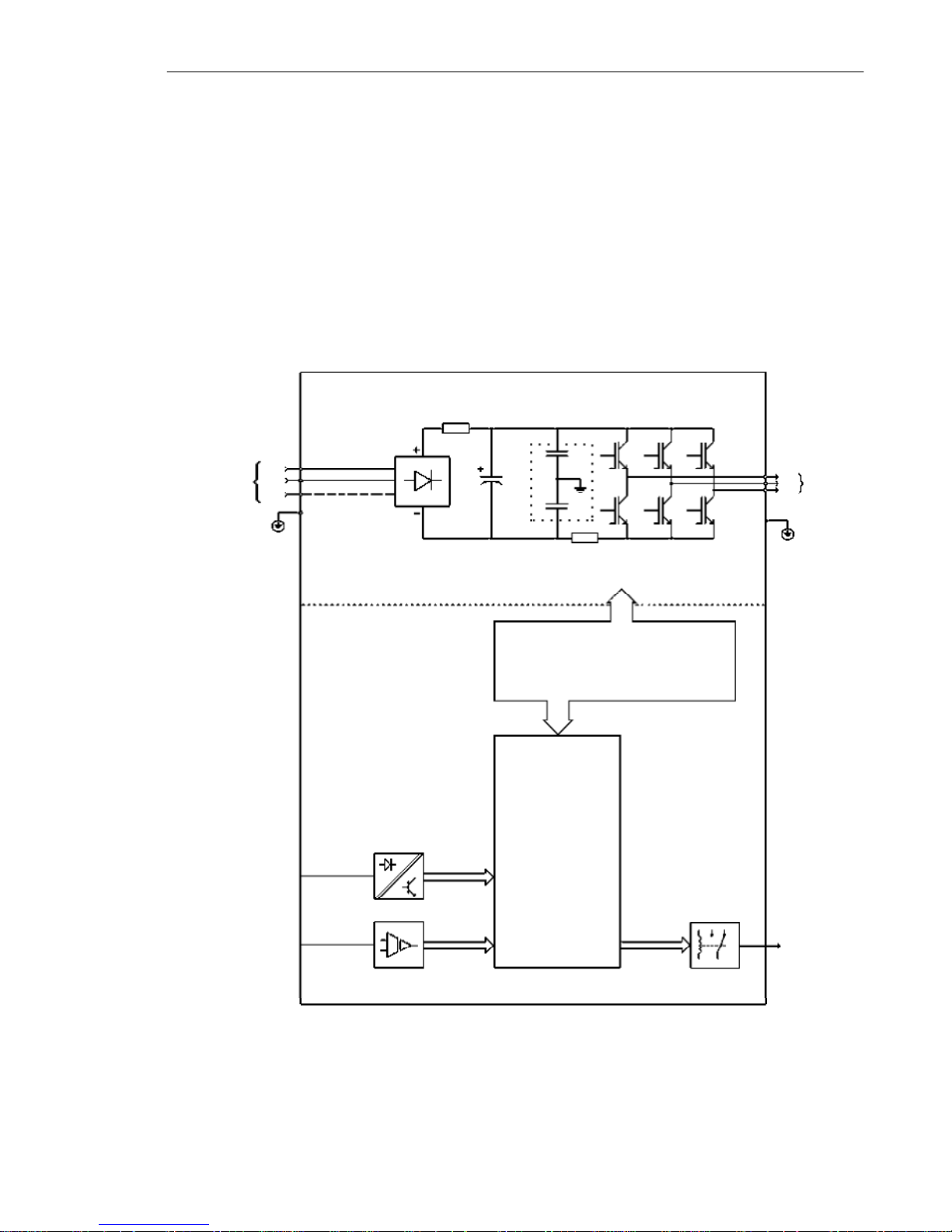
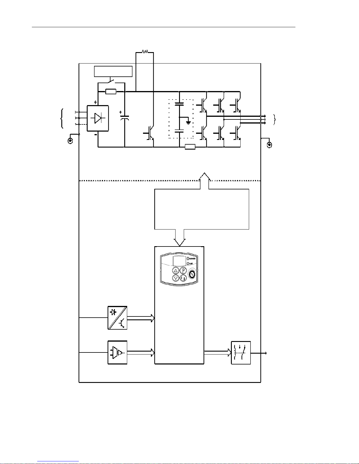
The block diagram below gives a general overview of the CFW-10.
Figure 2.1 - CFW-10 Block Diagram for models 1.6 A, 2.6 A and 4.0 A / 200-240 V (single-phase)
and 1.6 A, 2.6 A, 4.0 A and 7.3 A/200-240 V (three-phase)
Power
Supply
L/L1
PE
Analog
Input
(AI1)
Digital
Inputs
(DI1 to DI4)
POWER
CONTROL
POWER SUPPLY AND
CONTROL/POWER INTERFACES
"CCP10"
CONTROLBOARD
WITH DSP
Relay
Output
(RL1)
Motor
U
V
W
Rsh
NTC
RFI Filter
N/L2
L3
Page 16
16
CHAPTER 2 - GENERAL INFORMATION
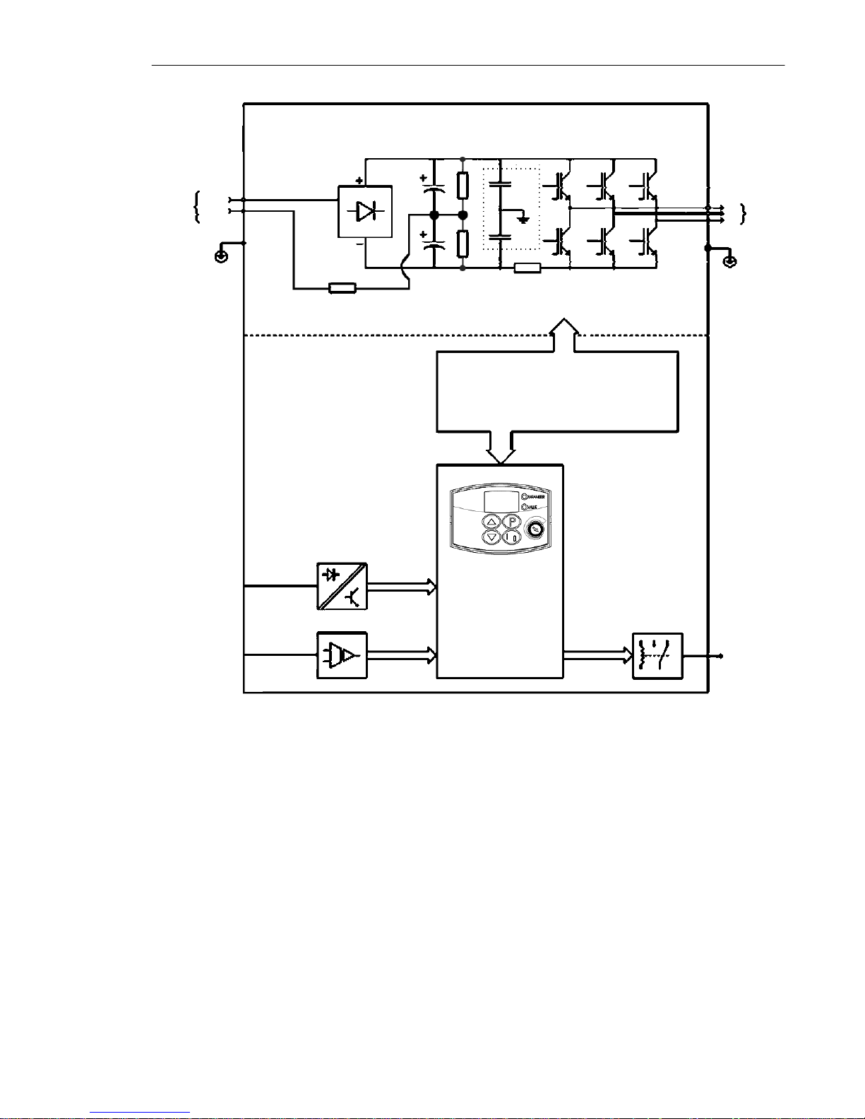
Figure 2.2 - CFW-10 Block Diagram for model 7.3 A and10.0 A/200-240V (single-phase)
and10.0 Aand 15.2 A/200-240V (three-phase)
Power
Supply
L/L1
PE
Analog
Input
(AI1)
Digital
Inputs
(DI1 to DI4)
POWER
CONTROL
POWER SUPPLY FOR
ELETRONICSAND INTERFACE
BETW EEN POWERAND CONTROL
"CCP10"
CONTROL
BOARD
WITH DSP
Relay
Output
(RL1)
Motor
U
V
W
Rsh
+UD
RFI Filter
N/L2
BR
Braking Resistor
(Optional)
Pre-Charge
L3
Page 17
17
CHAPTER 2 - GENERAL INFORMATION
Power
Suplly
L/L1
Analog
Input
(AI1)
Digital
Inputs
(DI1 to DI4)
POWER
CONTROL
POWER SUPPLY FOR
ELETRONICS
AND INTERFACE BETWEEN
POWERAND CONTROL.
"CCP10"
CONTROL
BOARD
WITH DSP
Relay
Output
(RL1)
Motor
U
V
W
Rsh
NTC
PE
PE
RFI Filter
N/L2
Figure 2.3 - CFW-10 Block Diagram for model 1.6A and 2.6A/110-127 V
Page 18
18
CHAPTER 2 - GENERAL INFORMATION
Figure 2.4 - CFW-10 Block Diagram for model 4.0 A/110-127V
Power
Suplly
L/L1
Analog
Input
(AI1)
Digital
Inputs
(DI1 to DI4)
POWER
CONTROL
POWER SUPPLY FOR
ELETRONICSAND INTERFACE
BETWEEN POWER AND CONTROL
"CCP10"
CONTROL
BOARD
WITH DSP
Relay
Output
(RL1)
Motor
U
V
W
Rsh
PE
PE
RFI Filter
N/L2
+UD BR
Braking Resistor
(Optional)
Pre-Charge
Page 19
19
CHAPTER 2 - GENERAL INFORMATION
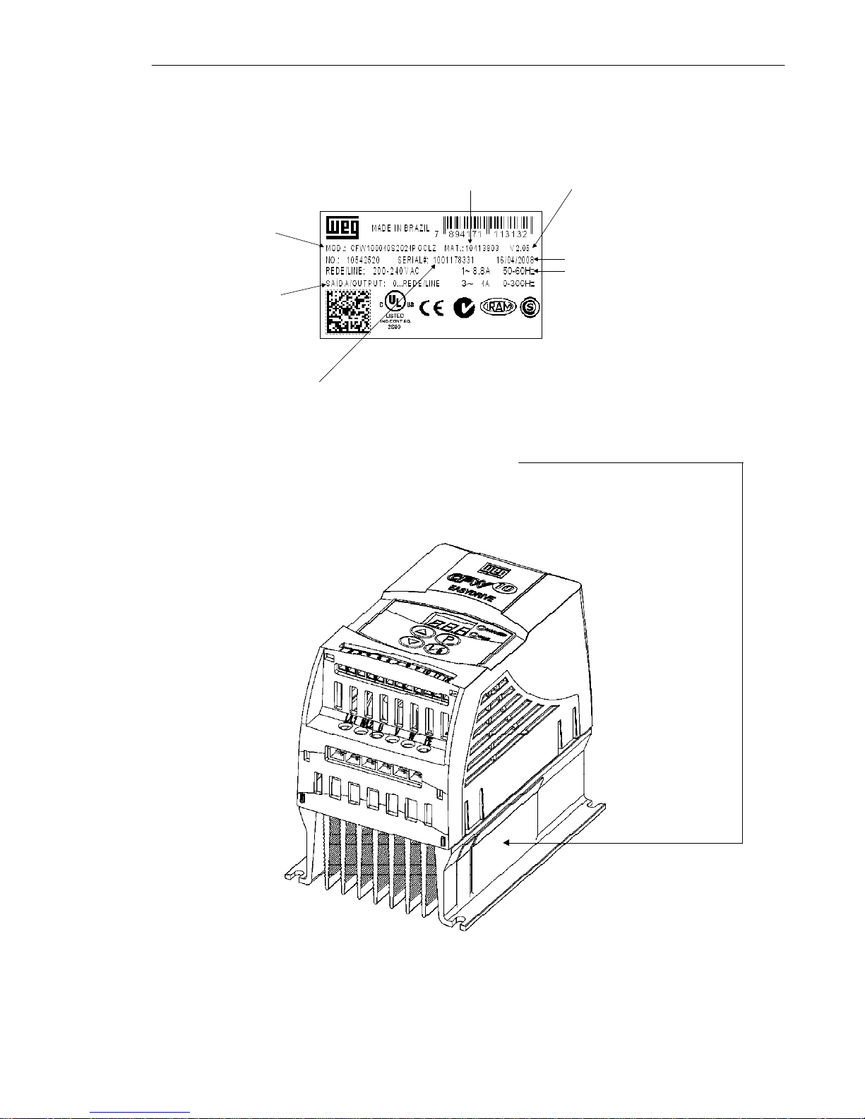
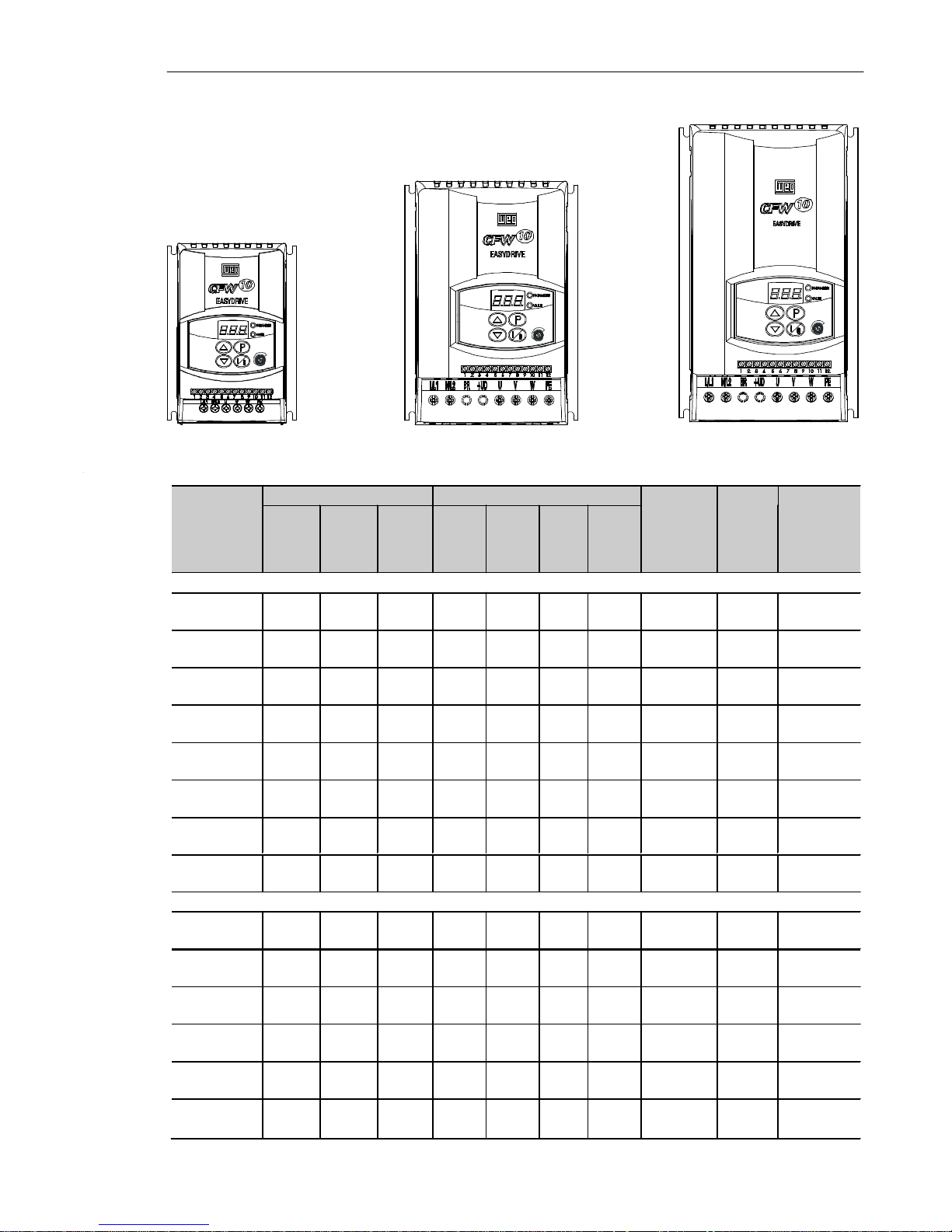
2.4 CFW -10 IDENTIFICATION
Figure 2.5 - Description andLocation of the Nameplate
LateralNameplateCFW-10
Serial Number
CFW-10 Model
Rated Output Data
(Voltage, Frequency)
Software
Version
Rated Input Data
(Voltage, Current, etc)
Manufacturing Date
WEG
Part Number
Page 20

20
CHAPTER 2 - GENERAL INFORMATION
NOTE!
The Option field (S or O) defines if the CFW-10 is a standard version or if it will be equipped with any optional devices.
If the standard version is required, the specification code ends here.
The model number has always the letter Z at the end. For example:
CFW100040S2024ESZ = standard 4.0 A CFW-10 inverter, single-phase at 200 V to 240 V input with manual in
English.
If the CFW-10 is equipped with any optional devices, you must fill out all fields in the correct sequence up to the last
optional device, the model number is completed with the letter Z.
HOW TO SPECIFY THE CFW-10 MODEL
CFW-10 0040 S 2024 P O _ _ _ _ _ _ _ _ Z
Special
Software
Blank =
standard
End
Code
Special
Hardware
Blank =
standard
Rated
Output
Current for
220 to 240 V:
0016 = 1.6 A
0026 = 2.6 A
0040 = 4.0 A
0073 = 7.3 A
0100 = 10.0 A
0152 = 15.2 A
110 to 127 V:
0016 = 1.6 A
0026 = 2.6 A
0040 = 4.0 A
Number of
phases of
the power
supply
S = single-
phase
T = three-
phase
Manual
Language:
P = Portuguese
E = English
S = Spanish
G = German
Power
supply:
2024 =
200 to 240 V
1112 =
110 to 127 V
Options:
S = standard
O = with
options
WEG
Series 10
Frequency
Inverter
Control
Board:
Blank =
standard
control
CL = Clean
PL = Plus
Built-in EMC
filter:
Blank =
standard
FA = with
EMC (class A)
filter
CP = Cold
Plate
heatsink
version
Page 21

21
CHAPTER 2 - GENERAL INFORMATION
2.5 RECEIVING
AND STORING
The CFW-10 is supplied in cardboard boxes.
There is a nameplateon the outside of the packing boxthat is identical
to that one on the CFW-10.
Check if the:
CFW-10 nameplate data matches with your purchase order.
The equipment has not been damaged during transport.
If any problem is detected, contact the carrier immediately.
If the CFW-10 is not installed immediately, store it in a clean and dry
room (storage temperatures between -25 °C and 60 °C). Cover it to
protect it against dust, dirt or other contamination.
ATTENTION!
When stored for a long time, it is recommended to power up and
keep the driverunning for 1 hour every year. Make sureto use a singlephase power supply (50 or 60 Hz) that matches the driverating without
connecting the motor to its output. After powering up the drive, keep it
off for 24 hours before using it again.
Page 22
22
CHAPTER 3
INSTALLATION AND CONNECTION
3.1 MECHANICAL
INSTALLATION
3.1.1 Environment
This chapter describes the procedures for the electrical and
mechanical installation of the CFW -10.
These guidelines and suggestions must be followed for proper
operation of the CFW-10.
The location of the inverter installation is an important factor to assure
good performance and high product reliability. For proper installation,
we make the following recommendations:
Avoid direct exposure to sunlight, rain, high moisture and sea air.
Avoid exposure to gases or explosive or corrosive liquids;
Avoid exposure to excessive vibration, dust, oil or any conductive
particles or materials.
Environmental Conditions:
Temperature : 0 ºC to 50 ºC (32 ºF to 122 ºF) - nominal conditions,
except for the 15.2 A model with Built-in filter (0 to 40 °C).
Relative Air Humidity: 5 % to 90 % - non-condensing.
Maximum Altitude: 1000 m (3.300 ft) - nominal conditions.
From 1000 m to 4000 m (3.300 ft to 13.200 ft): with 1 % current
derating for each 100 m (330 ft) above 1000 m (3.300 ft).
Pollution Degree: 2 (according to EN50178 and UL508C).
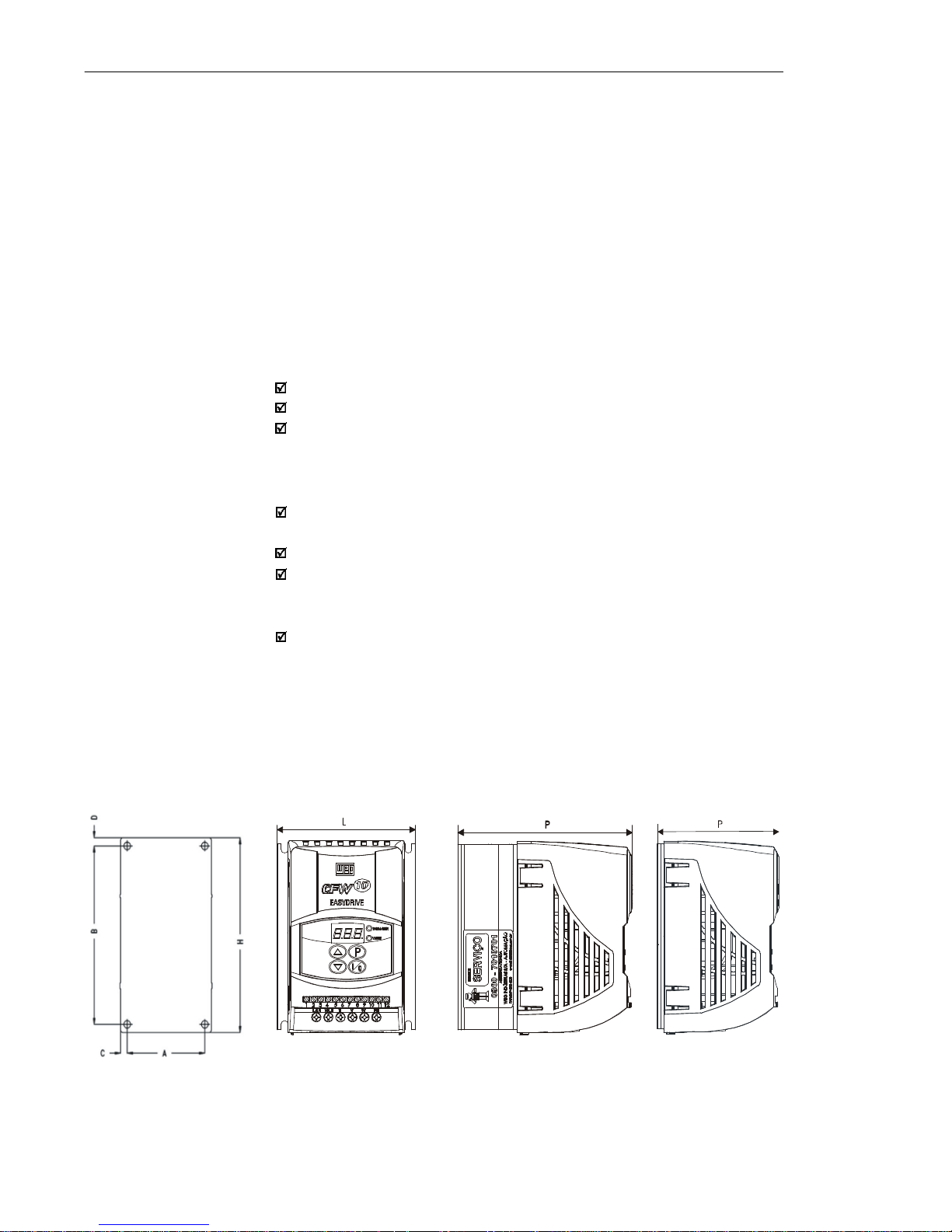
External dimensions and mounting holes for the CFW-10 shall be
according to figure 3.1 and table 3.1.
3.1.2 Dimensional of
CFW-10
MOUTING BASE
VIEW
FRONTAL
VIEW
SIDE VIEW
(STANDARD VERSION)
Figure 3.1 - Dimensional of CFW-10 - Sizes 1, 2 and 3
SIDE VIEW
(COLD PLATE
VERSION)
Page 23
23
CHAPTER 3 - INSTALLATION AND CONNECTION
Figure 3.1 - Dimensional of CFW-10 - Sizes 1, 2 and 3
Size 2
Size 3
Size 1
Table 3.1 a) Installation data (dimensions in mm (in)) – Refer to Section 9.1
Dim ensions Fixing Base
Model
Width
L
[mm]
(in)
Height
H
[mm]
(in)
Depth
P
[mm]
(in)
A
[mm]
(in)
B
[mm]
(in)
C
[mm]
(in)
D
[mm]
(in)
Mounting
Screw
Weight
[kg]
(lb)
Degree of
Protection
SING LE-PHASE
1.6 A /
200-240 V
95
(3.74)
132
(5.20)
121
(4.76)85(3.35)
120
(4.72)5(0.2)6(0.24)
M4 0.9
(1.98)
IP20
2.6 A /
200-240 V
95
(3.74)
132
(5.20)
121
(4.76)85(3.35)
120
(4.72)5(0.2)6(0.24)
M4 0.9
(1.98)
IP20
4.0 A /
200-240 V
95
(3.74)
132
(5.20)
121
(4.76)85(3.35)
120
(4.72)5(0.2)6(0.24)
M4 0.9
(1.98)
IP20
7.3 A /
200-240 V
115
(4.53)
161
(6.34)
122
(4.8)
105
(4.13)
149
(5.83)5(0.2)6(0.24)
M4 1.5
(3.31)
IP20
10.0 A /
200-240 V
115
(4.53)
191
(7.46)
122
(4.8)
105
(4.13)
179
(7.05)5(0.2)6(0.24)
M4 1.8
(3.96)
IP20
1.6 A /
110-127 V
95
(3.74)
132
(5.20)
121
(4.76)85(3.35)
120
(4.72)5(0.2)6(0.24)
M4 0.9
(1.98)
IP20
2.6 A /
110-127 V
95
(3.74)
132
(5.20)
121
(4.76)85(3.35)
120
(4.72)5(0.2)6(0.24)
M4 0.9
(1.98)
IP20
4.0 A /
110-127 V
115
(4.53)
161
(6.34)
122
(4.8)
105
(4.13)
149
(5.83)5(0.2)6(0.24)
M4 1.5
(3.31)
IP20
THREE-PH ASE
1.6 A /
200-240 V
95
(3.74)
132
(5.20)
121
(4.76)85(3.35)
120
(4.72)5(0.2)6(0.24)
M4 0.9
(1.98)
IP20
2.6 A /
200-240 V
95
(3.74)
132
(5.20)
121
(4.76)85(3.35)
120
(4.72)5(0.2)6(0.24)
M4 0.9
(1.98)
IP20
4.0 A /
200-240 V
95
(3.74)
132
(5.20)
121
(4.76)85(3.35)
120
(4.72)5(0.2)6(0.24)
M4 0.9
(1.98)
IP20
7.3 A /
200-240 V
95
(3.74)
132
(5.20)
121
(4.76)85(3.35)
120
(4.72)5(0.2)6(0.24)
M4 0.9
(1.98)
IP20
10.0 A /
200-240 V
115
(4.53)
161
(6.34)
122
(4.8)
105
(4.13)
149
(5.83)5(0.2)6(0.24)
M4 1.5
(3.31)
IP20
15.2 A /
200-240 V
115
(4.53)
191
(7.46)
122
(4.8)
105
(4.13)
179
(7.05)5(0.2)6(0.24)
M4 1.8
(3.96)
IP20
Page 24

24
CHAPTER 3 - INSTALLATION AND CONNECTION
Table 3.1 b) Cold Plate Version, installation data (dimensions in mm (in)) – Refer to Section 9.1
The Cold Plate version was designed in order to allow mounting the
“CP” CFW-10 frequency inverter in any heat dissipationsurface, since
following recommendations are fulfilled.
INSTALLATING THE FREQUENCY INVERTER ON THE HEAT
DISSIPATION SURFACE - STEPS
1. Mark out the positions of the mounting holes on the backing plate
where the frequency inverter will be located (see in figure 3.1
drawing and hole size).
2. The surface that is in contact with frequency inverter dissipation
surface must be free of dirt and burr. Standard requirements are:
the backing plate flatness (considering an area of 100 mm
2
(0.15 in2)) shall be less than 50 m and the roughness less than
10 m.
Dim ensions Fixing Bas e
Model
Width
L
[mm]
(in)
Height
H
[mm ]
(in)
Depth
P
[mm]
(in)
A
[mm ]
(in)
B
[mm]
(in)
C
[mm]
(in)
D
[mm]
(in)
Mounting
Screw
Weight
[kg]
(lb)
Degree of
Protection
SING LE-PHASE
1.6 A /
200-240 V
100
(3.94)
132
(5.20)82(3.23)90(3.54)
120
(4.72)5(0.2)6(0.24)
M4 0.7
(1.54)
IP20
2.6 A /
200-240 V
100
(3.94)
132
(5.20)82(3.23)90(3.54)
120
(4.72)5(0.2)6(0.24)
M4 0.7
(1.54)
IP20
4.0 A /
200-240 V
100
(3.94)
132
(5.20)82(3.23)90(3.54)
120
(4.72)5(0.2)6(0.24)
M4 0.7
(1.54)
IP20
7.3 A /
200-240 V
120
(4.72)
161
(6.34)82(3.23)
110
(4.33)
149
(5.83)5(0.2)6(0.24)
M4 1.0
(2.20)
IP20
10.0 A /
200-240 V
120
(4.72)
191
(7.46)82(3.23)
110
(4.33)
179
(7.05)5(0.2)6(0.24)
M4 1.2
(2.65)
IP20
1.6 A /
110-127 V
100
(3.94)
132
(5.20)82(3.23)90(3.54)
120
(4.72)5(0.2)6(0.24)
M4 0.7
(1.54)
IP20
2.6 A /
110-127 V
100
(3.94)
132
(5.20)82(3.23)90(3.54)
120
(4.72)5(0.2)6(0.24)
M4 0.7
(1.54)
IP20
4.0 A /
110-127 V
120
(4.72)
161
(6.34)82(3.23)
110
(4.33)
149
(5.83)5(0.2)6(0.24)
M4 1.0
(2.20)
IP20
THREE-PHASE
1.6 A /
200-240 V
100
(3.94)
132
(5.20)82(3.23)90(3.54)
120
(4.72)5(0.2)6(0.24)
M4 0.7
(1.54)
IP20
2.6 A /
200-240 V
100
(3.94)
132
(5.20)82(3.23)90(3.54)
120
(4.72)5(0.2)6(0.24)
M4 0.7
(1.54)
IP20
4.0 A /
200-240 V
100
(3.94)
132
(5.20)82(3.23)90(3.54)
120
(4.72)5(0.2)6(0.24)
M4 0.7
(1.54)
IP20
7.3 A /
200-240 V
100
(3.94)
132
(5.20)82(3.23)90(3.54)
120
(4.72)5(0.2)6(0.24)
M4 0.7
(1.54)
IP20
10.0 A /
200-240 V
120
(4.72)
161
(6.34)82(3.23)
110
(4.33)
149
(5.83)5(0.2)6(0.24)
M4 1.0
(2.20)
IP20
15.2 A /
200-240 V
120
(4.72)
191
(7.46)82(3.23)
110
(4.33)
179
(7.05)5(0.2)6(0.24)
M4 1.2
(2.65)
IP20
Page 25
25
CHAPTER 3 - INSTALLATION AND CONNECTION
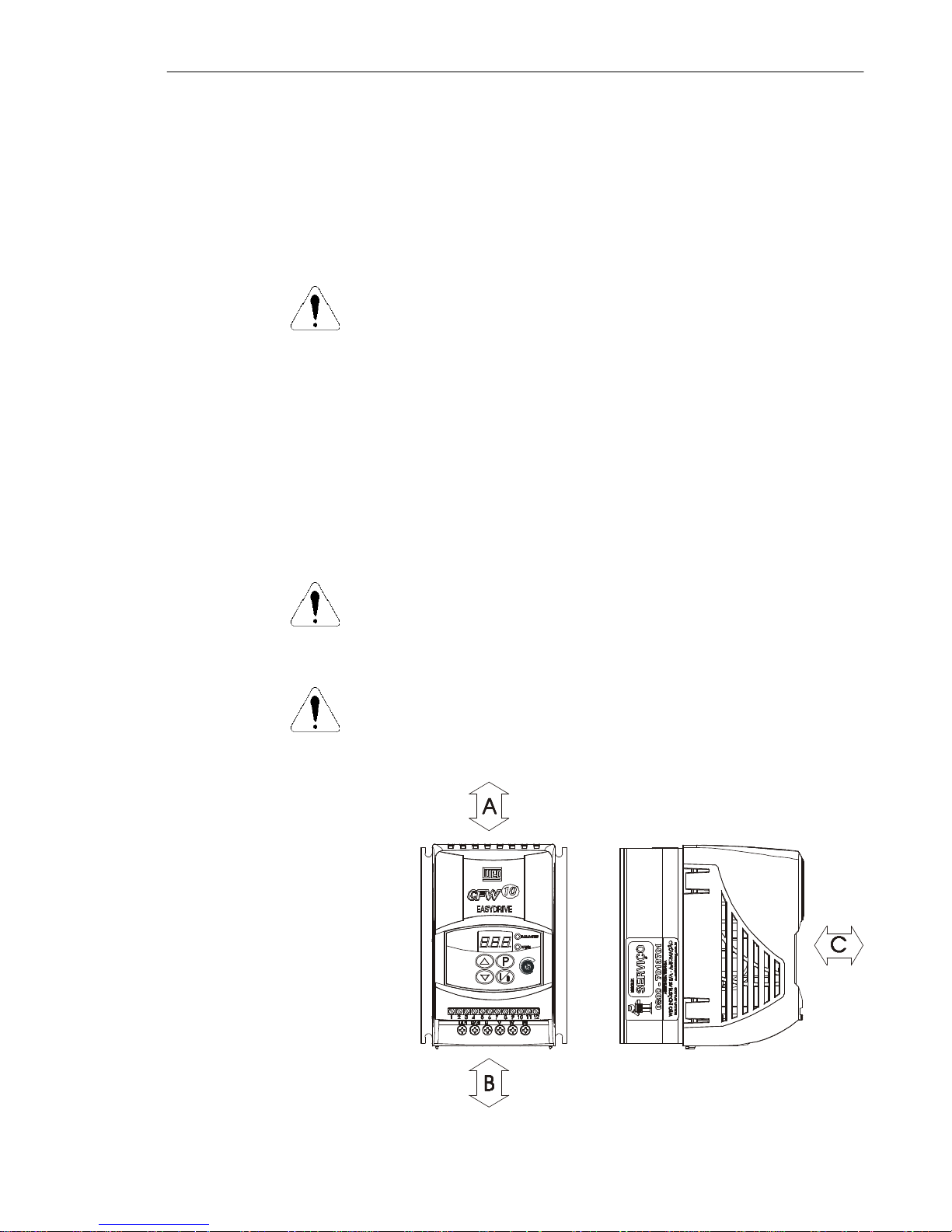
Figure 3.2 and table 3.2 show free space requirements to be left
around the drive.
Install the drive on a vertical position, following the recommendations
listed below:
1) Install the drive on a flat surface.
2) Do not install heat sensitive components immediately above the
drive.
ATTENTION!
When there are other devices installed at the top and at the bottom of
the drive, respect the minimum recommended distance (A + B) and
deflect the hot air coming from the device below.
ATTENTION!
Provide independent conduits for signal, control and power
conductors. (Refer to Electrical Installation). Separate the motor cables
from the other cables.
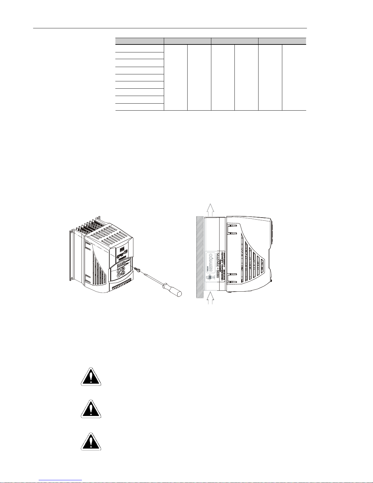
3.1.3 Mounting
Specification
3. Use (M4) mounting screws in order to fasten the frequency inver-
ter to the base plate.
4. After drilling the holes, clean the contact surface of the backing
plate and coat it with a thin thermal paste layer, or with a heat
conducting foil or similar product (approx. 100 m).
5. Continue the mechanical installation as indicated in Chapter 3.1.
6. Electrical installation shall be performed as indicated in the
Chapter 3.2.
ATTENTION!
After operation, check P008. This parameter must not exceed 90 ºC.
Figure 3.2 - Free-spacefor Cooling
Page 26
26
CHAPTER 3 - INSTALLATION AND CONNECTION
3.1.3.1 Panel
Mounting
When drives are installed inside panels or inside closed metallic
boxes, proper cooling is required to ensure that the temperature
around the drivewill not exceed the maximum allowable temperature.
Refer to Section 9.1 for Power Dissipation data.
3.1.3.2 Mounting
Surface
Figure 3.3 shows the installation procedure of the CFW-10 on a
mounting surface.
Figure 3.3 - MountingProcedures forthe CFW-10
3.2 ELECTRICALINSTALLATION
DANGER!
The information below will be a guide to achieve a proper installation.
Follow also all applicable local standards for electrical installations.
DANGER!
Be sure the AC input power has been disconnected before making
any terminal connection.
DANGER!
The CFW-10 shall not be used as an emergency stop device. Use
additional devices proper for this purpose.
Air Flow
Table 3.2 - Freespace requirements
CFW-10 Model
1.6 A / 200-240 V
2.6 A / 200-240 V
4.0 A / 200-240 V
7.3 A / 200-240 V
10.0 A/200-240 V
15.2 A/200-240 V
1.6 A / 110-127 V
2.6 A / 110-127 V
4.0 A / 110-127 V
A B C
30 mm 1.18 in 50 mm 2 in 50 mm 2 in
Page 27
27
CHAPTER 3 - INSTALLATION AND CONNECTION
3.2.1 Power and
Grounding
Terminals
Description of the Power Terminals:
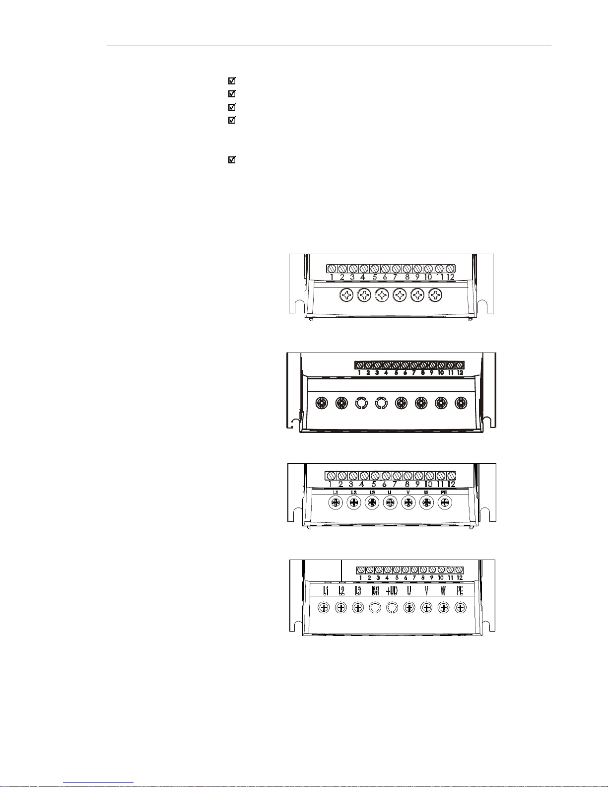
L/L1, N/L2, L3: AC power supply.
U, V and W: Motor connection.
PE: Grounding connection.
BR: Connection terminal for the braking resistor. Not available for
1.6 A, 2.6 A and 4 A/200-240 V and 1.6 A and 2.6 A/110-127 V and
7.3 A/200-240 V three-phase models.
+UD: Positiveconnection terminal (DC Link). This terminal is used
to connect the braking resistor (connect also the BR terminal). Not
available for 1.6 A, 2.6 A and 4.0 A/200-240 V and 1.6 A and 2.6 A/
110-127 V and 7.3 A/200-240 V three-phase models.
a) Models 1.6 A, 2.6 A and 4.0 A/200-240 V and 1.6A and 2.6 A/110-127 V (single-phase)
b) Models 7.3 A and 10 A/200-240 V and 4.0 A/110-127 V (single-phase)
L/L1 N/L2 U V W PE
L/L1 N/L2 BR + UD U V W PE
c) Models 1.6 A, 2.6 A, 4.0 A, 7.3 A/200-240 V (three-phase)
d) Models 10.0 A and 15.2 A/200-240 V (three-phase)
Figure 3.4 a) b) c) d) - CFW-10Power Terminals
Page 28

28
CHAPTER 3 - INSTALLATION AND CONNECTION
3.2.3 Wiring and Fuses for
Power and Grounding
ATENTION!
Provide at least 0.25 m (10 in) spacing between low voltage wiring
and drive/motor cables. For instance: PLC’s, temperature monitoring
devices, thermocouples, etc.
Table 3.3 presents minimum cable diameter and circuit breaker rating
for the CFW-10. Tightening torque shall be as indicated in table 3.4.
All power wiring (cooper) shall be rated for 70 ºC minimum.
Table 3.3 -Recommended wire cross-section and circuit-breakers -use (70ºC) copper
wiresonly
3.2.2 Location of the Power,
Grounding and Control
Connections
ControlXC1
Power
Figure 3.5 - Locationof the Powerand Control Connections
Circuit-Breaker
Rated Inverter
Current [A]
Motor
Wiring
[mm²]
Grounding
Wir ing
[mm²]
Power
Cables
[mm ²]
Maximum
Cables
[mm²]
Current
WEG
Model
SINGLE-PHASE MODELS
1.6 (200-240 V ) 1.5 2.5 1.5 2.5 6 MPW25-6.3
1.6 (110-127 V ) 1.5 2.5 1.5 2.5 10 MPW25-10
2.6 (200-240 V ) 1.5 2.5 1.5 2.5 10 MPW25-10
2.6 (110-127 V ) 1.5 2.5 2.5 2.5 16 MPW25-16
4.0 (200-240 V ) 1.5 2.5 1.5 2.5 16 MPW25-16
4.0 (110-127 V ) 1.5 4.0 2.5 4.0 20 MPW25-20
7.3 (200-240 V ) 2.5 4.0 2.5 4.0 20 MPW25-20
10.0 (200-240 V) 2.5 4.0 4.0 4. 0 25 MPW25-25
THREE-PHASE MODELS
1.6 (200-240 V ) 1.5 2.5 1.5 2.5 2.5 MPW 25-2.5
2.6 (200-240 V ) 1.5 2.5 1.5 2. 5 6.3 MPW 25-6.3
4.0 (200-240 V ) 1.5 2.5 1.5 2. 5 10 MPW25-10
7.3 (200-240 V ) 2.5 4.0 2.5 4. 0 15 MPW25-15
10.0 (200-240 V) 2.5 4.0 4.0 4. 0 20 MPW25-20
15.2 (200-240 V) 4.0 4.0 4.0 4. 0 25 MPW25-25
Page 29
29
CHAPTER 3 - INSTALLATION AND CONNECTION
NOTE!
Cable dimensions indicated in table 3.3 are reference values only.
Installation conditions and the maximum acceptable line voltage drop
shall be considered when sizing the power cables.
Table 3.4 -Recommendedtighteningtorques forpower connections
a) Models 1.6 A, 2.6 A and 4.0 A/200-240 V and 1.6 A and 2.6 A/110-127 V (single-phase)
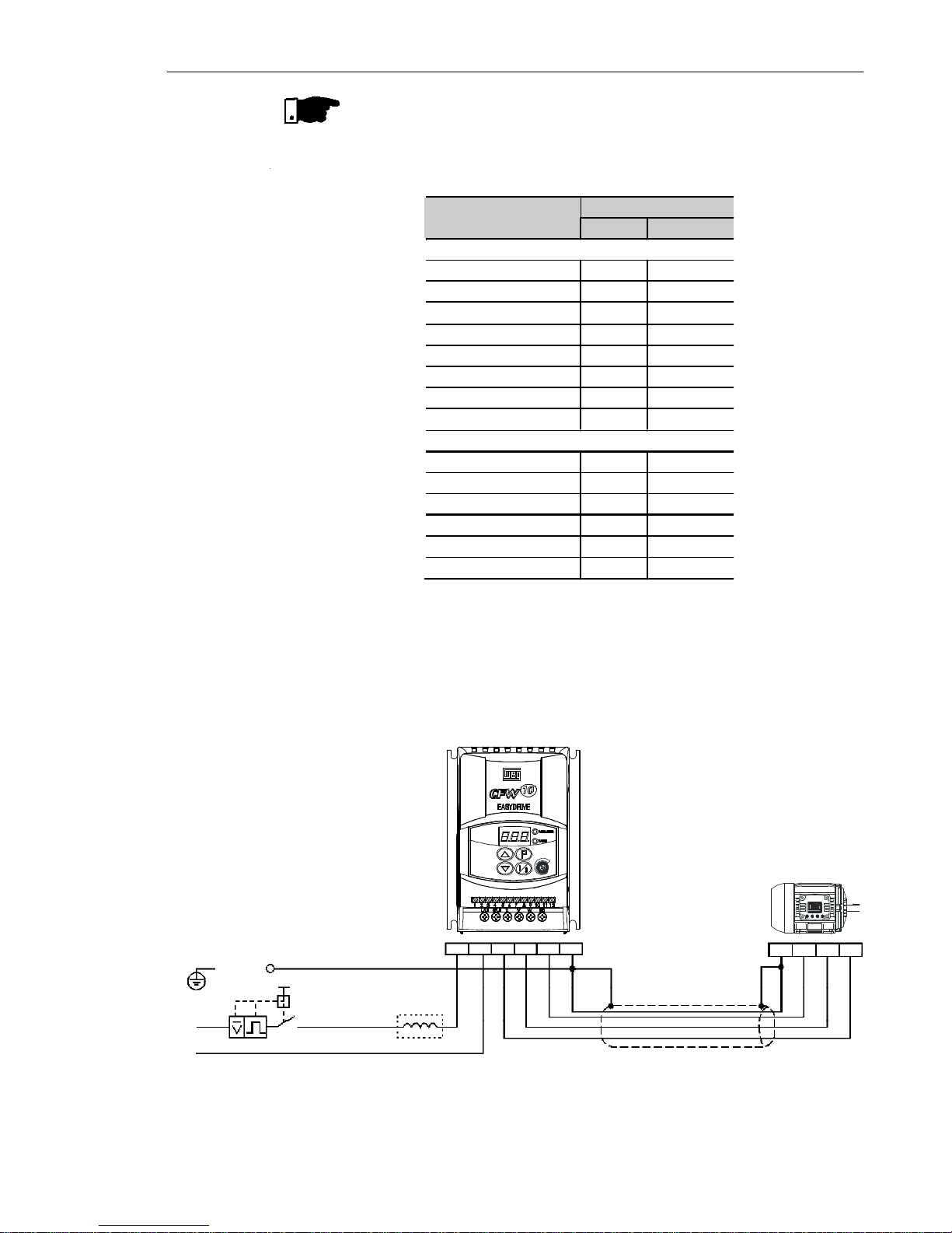
3.2.4 Power Connections
POWER SUPPLY
L/L1
PE
PE UVW
SHIELDING
Q1
N/L2
U V W PE
N/L2
L/L1
Figure3.6 a) - Groundingand powersupply connections
Power Cables
Model
N.m Lbf.in
SINGLE-PHASE
1.6 A / 200-240 V 1.0 8.68
2.6 A / 200-240 V 1.0 8.68
4.0 A / 200-240 V 1.0 8.68
7.3 A / 200-240 V 1.76 15.62
10.0 A / 200-240 V 1.76 15.62
1.6 A / 110-127 V 1.0 8.68
2.6 A / 110-127 V 1.0 8.68
4.0 A / 110-127 V 1.76 15.62
THREE-PHASE
1.6 A / 200-240 V 1.0 8.68
2.6 A / 200-240 V 1.0 8.68
4.0 A / 200-240 V 1.0 8.68
7.3 A / 200-240 V 1.0 8.68
10.0 A / 200-240 V 0.5 4.4
15.2 A / 200-240 V 0.5 4.4
Page 30
30
CHAPTER 3 - INSTALLATION AND CONNECTION
b) Models 7.3 A to 10 A/200-240 V and 4.0 A/110-127 V (single-phase)
POWER SUPPLY
SHIELDING
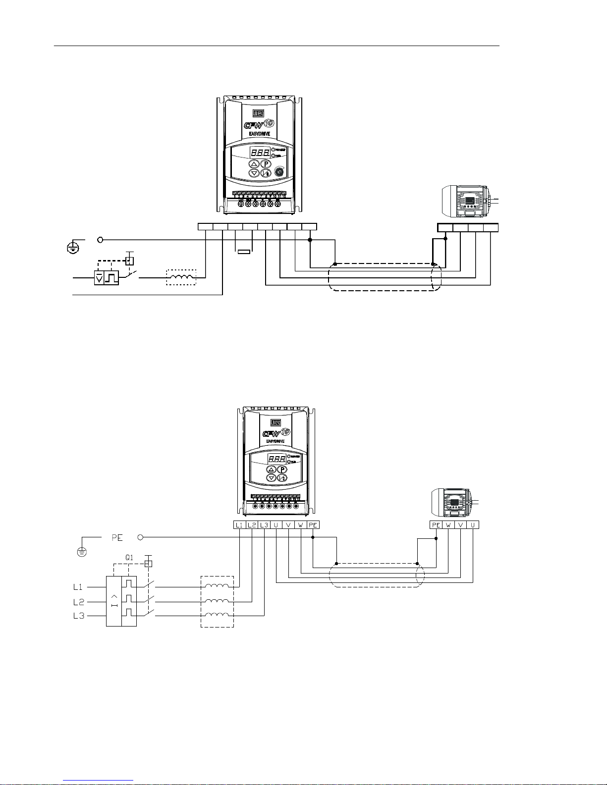
c) Models 1.6 A, 2.6 A, 4.0 A and 7.3 A/200-240 V (three-phase)
Figure 3.6 b) c) - Grounding and powersupply connections
POWER SUPPLY
L/L1
PE
PE UVW
SHIELDING
Q1
N/L2
U V W PE
N/L2
L/L1 +UDBR
Braking
Resistor
Page 31

31
CHAPTER 3 - INSTALLATION AND CONNECTION
SHIELDING
BRAKING
RESISTOR
Figure3.6 d) - Groundingandpower supplyconnections
d) Models 10.0 A and 15.2 A/200-240 V (three-phase)
DANGER!
Use a disconnecting device at the drive AC-input power supply. This
device shall be capable of disconnecting the drive from the power
supply when necessary (for maintenance purposes, for instance).
ATTENTION!
The drive AC-input power supply shall have a grounded neutral
conductor.
NOTE!
The AC-input voltage shall match the drive rated voltage.
Supply line capacity:
The CFW-10 is capable of withstanding up to 30.000 symmetrical
rms Amperes at 127 V/240 V.
If the CFW-10 is installed in networks with higher symmetrical rms
currents (> 30.000 Amps), an appropriate protection mean shall
be provided (fuses or circuit breaker).
Line Reactors
The use of line reactors is dependent upon several factors. Refer to
Chapter 8.2 in order to understand these requirements.
NOTE!
Capacitors for power factor correction are not required at the input
(L/L1, N/L2, L3) and shall not be connected at the output (U, V, W ).
3.2.4.1 AC Input
Connection
Page 32

32
CHAPTER 3 - INSTALLATION AND CONNECTION
Rheostatic Braking
For the drives with the rheostatic braking optional, the braking resistor
shall be installed externally. Refer to figure 8.4 for correct braking
resistor installation. Size the braking resistor according to the
application and respecting the maximum admissible current for the
braking circuit.
Use twisted pair to connect the braking resistor to the drive. Run this
cable separately from the signal and control cables. If the braking
resistor is installed inside the drive panel, the additional resistor heat
dissipation shall be considered when defining the panel ventilation.
DANGER!
The drive must be grounded for safety purposes (PE).
The ground connection must comply with the local regulations. For
grounding purposes, use cables with cross sections as indicated in
table 3.3. Make the ground connection to a grounding bar or to the
general grounding point (resistance 10 ohms).
DANGER!
The grounding wiring shall be installed away from equipment operating
with high currents (for instance: high voltage motors, welding machines,
etc).
If several drives are used together, refer to figure 3.7.
3.2.4.3 Grounding
Connections
3.2.4.2 Output
Connection
The drive has electronic protection against motor overload. This
protection shallbe set according to the specific motor. W hen the same
drive is connected to several motors, individual overload relays shall
be used for each motor protection.
ATTENTION!
If a disconnecting switch or a contactor is inserted between the drive
output and the motor input, do not operate them when motor is running
or when drive is enabled. Maintain the electrical continuity of the motor
cable shield.
Page 33

33
CHAPTER 3 - INSTALLATION AND CONNECTION
NOTE!
Do not use the neutral conductor for grounding purposes.
ATTENTION!
The AC input for the drive supply must have a grounded neutral
conductor.
Electromagnetic Interference (EMI)
Shielded cableor metallic conduit shall be used for motor wiring when
electromagnetic interference (EMI) caused by the drive interferes in
the performance of other equipment. Connect oneend of the shielding
to the drive grounding point and the other end to the motor frame.
Motor Frame
Always ground the motor frame. Ground the motor in the panel where
the drive is installed or ground it to the drive. The drive output wiring
must be laid separately from the input wiring as well as from the control
and signalcables.
Figure 3.7 - Grounding connections for morethan one drive
Page 34

34
CHAPTER 3 - INSTALLATION AND CONNECTION
3.2.5 Signal and
Control
Connections
The signal (analog input) and control connections (digital inputs and
relay output) are made on the XC1 connector of control board (see
location in figure 3.5).
Figure 3.8 - Description of the XC1 terminal of the control board
XC1Terminal
1 DI1
2 DI2
3 DI3
4 DI4
5 GND
6 AI1
7 GND
8 AI1
9 +10 V
10 NC
11 Common
12 NO
Description
Factory Default Function
Digital Input 1
General Enable(remotemode)
Digital Input 2
FWD/REV (remote mode)
Digital Input 3
Local/Remote
Digital Input 4
Start/Stop (remote mode)
0 V Reference
Analog Input 1
Freq.Reference
(remotemode)
0 V Reference
Analog Input (voltage)
Frequency Reference (remote)
Potentiometer Reference
Relay NC Contact
No Fault
Relay Output - common point
Relay NO Contact
No Fault
Specifications
4 isolated digital inputs
Minimum High Level: 10 Vdc
Maximum High Level: 30 Vdc
Maximum Low Level: 3 Vdc
Input current: -11 mA @ 0 Vdc
Max. input current: -20 mA
Not interconnected with PE
Current:(0 to20)mAor (4to 20) mA
Impedance: 500 Resolution:7 bits
Not interconnected with PE
Voltage: 0 to 10 Vdc
Impedance:100 k Resolution: 7bits
Max. input voltage: 30 Vdc
+10 Vdc, ± 5 %, capacity: 2 mA
CW
CCW
5k
Contact capacity:
0.5 A / 250 Vac
1.0 A / 125 Vac
2.0 A / 30 Vdc
(+)
(-)
Relay
10 12
11
NOTE!
If the input current from (4 to 20) mA is used as standard, do not
forget to set the Parameter P235 which defines the signal type at
AI1.
The analog input AI1 and the Relay output, (XC1:6…12) are
not available on Clean version of the CFW-10.
(0 to 20) mA
(4 to 20) mA
Not available on Clean version
Page 35

35
CHAPTER 3 - INSTALLATION AND CONNECTION
Figure 3.9 - Shield connection
Connect to earth
Do not
ground
Inverter
side
Insulate with
tape
4) For wiring distances longer than 50 m (150 ft), the use of
galvanic isolators is required for the XC1:6 to XC1:9 analog signals.
5) Relays, contactors, solenoids or eletromagnetic braking coils
installed near inverters can eventually generate interferences
in the control circuit. To eliminate this interference, connect RC
suppressor in parallel with the coils of AC relays. Connect
free-wheeling diode in case of DC relays.
6) When analog reference (AI1) is used and the frequency
oscillates (problem caused by electromagnetic interference)
connect XC1:7 to the inverter grounding bar.
During the signal and control wire installation note the following:
1) Cable cross section: (0.5 to 1.5) mm² / (20 to 14) AWG.
2) Max. Torque: 0.50 N.m (4.50 lbf.in).
3) XC1 wiring must be connected with shielded cables and
installed at least 10 cm (3.9 in) minimum separately from other
wiring (power, control at 110/220 V, etc) for lengths up to
100 m (330 ft) and 25 cm (9.8 in) minimum for total lengths over
100 m (330 ft).
If t he crossing of these c ables is unavoidable, install them
perpendicular, maintaining a mimimum separation distance
of 5 cm (2 in) at the crossing point.
Connect the shield as shown below:
Page 36

36
CHAPTER 3 - INSTALLATION AND CONNECTION
3.2.6 Typical
Terminal
Connections
Connection 1
With the factory default programming, it is posible to operate the
inverter in localmode with the minimum connections shown in figure
3.6 (Power) and without control connections. This operation mode is
recommended for users who are operating the inverter for the first
time as initial learning about equipment. Note that any connection is
needed on control terminal.
For start-up according to this operation mode, refer to Chapter 5.
Connection 2
Command enabling via terminals.
S1: FW D/REV
S2: Local/Remote
S3: Start/Stop
R1: Potentiometer for
Speed Setting
Figure 3.10 - Wiring forConnection 2
DI1 - No Function (HMI) or
General Enabling (Terminals)
DI2 - FW D/REV
DI3 - Local/Remote
GND
AI1 (0.4 to 20 mA)
GND
AI1 (0 to 10 Vdc)
+10 V
NC
Common
NO
DI4 - No Function (HMI) or
Start / Stop(Terminals)
S1
1 2 3 4 5 6 7 8 9 10 11 12
5 K
NOTE!
Thefrequency referencecan besent via AI1 analog input (as shown
in figure above), via keypad HMI-CFW10, or via any other source
(see description of Parameters P221 and P222).
When a line fault occurs by using this type of connection with switch
S3 at position "RUN", the motor will be enabled automatically as
soon as the line is re-established.
Function 2 configuration is not possible on CFW-10 Clean version.
S2 S3
Not available on Clean version
Page 37

37
CHAPTER 3 - INSTALLATION AND CONNECTION
Figure 3.11 - Wiring for Connection 3
NOTE!
S1 and S2 are push buttons, NO and NC contact, respectively.
The speed reference can be realized via Analog Input AI1 (as in
connection 2), via keypad (HMI-CFW10), or via any other source
(See description of parameters P221 and P222).
When a line fault occurs by using this connection with the motor
running and the S1 and S2 switches are in original position (S1
openned and S2 closed), the invert er will not be enabled
automatically as soon as the line is re-restablished.
The drive will be enabled only when S1 switch is closed. (Pulse on
the “Start” digital input).
The Start/Stop function is described in Chapter 6.
S1: Start
S2: Stop
S3: FW D/REV
DI1 - Start (Start)
DI2 - Stop (Stop)
DI3 - Local/Remote
GND
AI1 (0.4 to 20 mA)
GND
AI1 (0 to 10 Vdc)
+10 Vdc
NC
Common
NO
DI4- Forward/Reverse
S3S2
1 2 3 4 5 6 7 8 9 10 11 12
S1
Connection 3
Start/Stop function enabling (three-wire control):
Set DI1 to Start: P263 = 13
Set DI2 to Stop: P264 = 14
Set P229 = 1 (commands via terminals) if you want the 3-wire control
in local mode.
Set P230 = 1 (commands via terminals) if you want the 3-wire control
in remote mode.
FWD / REV Selection:
Program P265 = 5 (DI3) or P266 = 5 (DI4), according to the selected
digital input (DI).
If P265 and P266 0, the direction of rotation is always FW D.
Page 38

38
CHAPTER 3 - INSTALLATION AND CONNECTION
Connection 4
Enabling of the FWD/REV function:
Set DI1 to Forward Run : P263 = 9
Set DI2 to Reverse Run: P264 = 10
Make sure the inverter commands are via terminals, i.e., set
P229 = 1 to local mode.
NOTE!
The speed reference can be realized via Analog Input AI1 (as in
connection 2), via keypad (HMI), or via any other source (see
description of parameters P221 and P222).
When a line fault occurs in this connection modewith switch S1 or
switch S2 is closed, the motor will be enabled automatically as
soon as the line is re-restablished.
Figure 3.12 - Wiring forConnection 4
DI4 - No Function / Ramp
Enabling
S1 open: Stop
S1 closed: Forward Run
S2 open: Stop
S2 closed: Reverse Run
DI1 - Forward Run
DI2 - Reverse Run
DI3 - Local/Remote
GND
AI1 (0.4 to 20 mA)
GND
AI1 (0 to 10 Vdc)
+10 Vdc
NC
Common
NO
S2S1
1 2 3 4 5 6 7 8 9 10 11 12
The CFW-10 inverter series was designed considering all safety and
EMC (ElectroMagnetic Compatibility) aspects.
The CFW-10 units do not have an intrinsic function until connected
with other components (e. g. a motor). Therefore, the basic product is
not CE marked for compliance with the EMC Directive. The end user
takes personal responsibility for the EMC compliance of the whole
ins tallation. H owever, when ins talled accor ding t o th e
recommendations described in the product manual and including the
recommended filters and EMC measures the CFW -10 fulfill all
requirements of the (EMC Directive 89/336/EEC) as defined by the
EN61800-3 "EMC Product Standard for Adjustable Speed
Electrical Power Drive Systems - specific standard for variable
speed drives.
The conformity of the complete CFW-10 series is based on tests
performed on sample models. A Technical Construction File (TCF)
was prepared, checked and approved by a Competent Body.
3.3 European EMC
Directive Requirements
for Conforming
Installations
Page 39

39
CHAPTER 3 - INSTALLATION AND CONNECTION
Figure 3.13 below shows the EMC filters connection.3.3.1 Installation
Figure 3.13- EMCfilter connection- general condition
The following items are required in order to have an appropriated
installation:
1) The motor cable shall be armored, or installed inside a metallic
conduit or trunking with equivalent attenuation. Ground the screen/
metallic conduit at both ends (inverter and motor).
2) Control (I/O) and signal wiring shall be shielded or installed inside
a metallic conduit or trunking with equivalent attenuation.as possible.
3) The inverter and the external filter shall be closely mounted on a
common metallic back plate. Ensure a good electrical connection
between the inverter heatsink, the filter frame and the back plate.
4) The wiring between the filter and theinverter shall be kept as short.
5) The cable shield (motor and control) shall be solidly connected to
the common back plate, using metallic brackets.
6) Grounding shall be performed as recommended in this user’s guide.
7) Use short and thick cables to ground the external filter or inverter.
When an external filter is used, ground only the filter (input) - the
inverter ground connection is performed through the metallic back
plate.
8) Ground the back plate using a braid, as short as possible. Flat
conductors (e.g. braids or brackets) have lower impedance at high
frequencies.
9) Use cable glands whenever possible.
Transformer
Grounding rod
ProtectiveGrounding
Motor
PE
CFW-10
L2/N
L1/L
PE
PE
XC1
1 to 12
U
Controling and signal wiring
V
W
PE
L1/L
L2/N
L2
L1
PE
External
input RFI
filter
Metalic cabinet when necessary
Page 40

40
CHAPTER 3 - INSTALLATION AND CONNECTION
EMC phenomenon
Emission:
Conducted emissions (mains
terminal disturbance voltage - freq
band 150 kHz to 30 MHz)
Radiated emissions (electromagnetic
radiation disturbance - freq band
30 MHz to 1000 MHz)
Immunity:
Electrostatic discharge (ESD)
Fast Transient-Burst
Conducted radio-frequency
common mode
Surge
Radio-frequencyelectromagnetic field
Basic standard
for test method
IEC/EN61800-3
IEC 61000-4-2
IEC 61000-4-4
IEC 61000-4-6
IEC 61000-4-5
IEC 61000-4-3
Level
“First environment”
(1)
, restricted distribution
(3)
Class B, or;
“First environment”
(1)
, restricted distribution
(4)(5)
Class A1, or;
“Second environment”
(2)
, unrestricted distribution
(3)(6)
Classe A2
Note: It depends on the drive model and on the motor
cable length (Refer to table 3.5.2).
“First environment”
(1)
, restricted distribution
(4)(5)
6 kV contact discharge
4 kV/2.5 kHz (capacitive clamp) input cable; 2 kV/
5 kHz control cables; 2 kV/5 kHz (capacitive
clamp) motor cable;
0.15 to 80 MHz; 10 V; 80 % AM (1 kHz) - motor
control and remote Keypad cable HMI Remote
1.2/50 s, 8/20 s;
1 kV coupling line to line;
2 kV coupling line to earth
80 to 1000 MHz; 10 V/m; 80 % AM (1 kHz)
3.3.2 Specification of the
Emission and Immunity
Levels
Notes:
(1) "First environment": environment that includes domest ic
premises. It also includes establishments directly connected
without intermediate transformers to a low-voltage power supply
network which supplies buildings used for domestic purposes.
(2) "Second environment": environment that includesall establishments
other than those directly connected to a low-voltage power supply
network which supplies buildings used for industrial purposes.
(3) Unrestricted distribution: mode of sales distribution in which the
supply of equipment is not dependent on the EMC competence
of the customer or user for the application of drives.
(4) Restricted distribution: mode of sales distribution in which the
manufacturer restricts the supply of equipment to suppliers,
customers or users who separately or jointly have technical
competence in the EMC requirements of the application of drives.
(source: these definitions were extracted from the product
standard IEC/EN61800-3 (1996) + A11 (2000))
Page 41

41
CHAPTER 3 - INSTALLATION AND CONNECTION
3.3.3 Inverter and
Filters
Table 3.5.2 shows the inverter models, its respective EMC filter and
the EMC category classification. Refer to section 3.3.2 for EMC
category description and to section 3.3.4 for external filters
characteristics.
Table 3.5.1- List of frequency drive models, EMC filters and EMC categories
(5) For installation in residential environments with conducted
emission level Class A1 (according to table 3.5.2), please,
consider the following:
This is a product of restricted sales distribution class according
to the product standard IEC/EN61800-3 (1996) + A11 (2000). In
a domestic environment this produc t may cause radio
interference in which case the user may be required to take
adequate measures.
(6) When installing drives that meet ClassA2 for conducted emission
level, i.e. industrial environment and unrestricted distribution
(according to table 3.5.2), observe the following:
This product is specifically designed for use in industrial lowvoltage power supply networks (public networks) that not supply
residential buildings. This product may cause radio frequency
interference in a domestic environment.
Inverter Model with
Built-in EMC Filter
(single-phase)
EMC Class
1.6 A / 200-240 V
2.6 A / 200-240 V
4.0 A / 200-240 V
7.3 A / 200-240 V
10.0 A / 200-240 V
Class A1.
Maximum motor cable length 7 meters (22.9 ft).
Class A2.
Maximum motor cable length 50 meters (164 ft).
Switching frequency 5 kHz.
Page 42

42
CHAPTER 3 - INSTALLATION AND CONNECTION
Note: Maximum switching frequency is 5 kHz.
Table 3.5.2 - List of frequency drive models, EMCfilters and EMC categories
NOTE!
The CFW -10 inverters with three-phase supply do not have EMC
filters.
Inverter Model
(single-phase)
Input RFI
Filter
EMC Class
1.6 A / 200-240 V
2.6 A / 200-240 V
4.0 A / 200-240 V
1.6 A / 110-127 V
2.6 A / 110-127 V
Footprint / Booksize
Model:
B84142A0012R212
(EPCOS)
Standard Model:
B84142-A20-R
(EPCOS)
Class A1.
Maximum motor cable length is 30 meters (98.4 ft).
Class A2.
Maximum motor cable length is 50 meters (164 ft).
Class B.
Maximum motor cable length is 5 meters (16.4 ft).
7.3 A / 200-240 V
4.0 A / 110-127 V
Footprint / Booksize
Model:
B84142B18R212
(EPCOS)
Class A1.
Maximum motor cable length is 30 meters (98.4 ft).
Class A2.
Maximum motor cable length is 50 meters (164 ft).
Class B.
Maximum motor cable length is 5 meters (16.4 ft).
7.3 A / 200-240 V
4.0 A / 110-127 V
(EPCOS)
Standard Model:
B84142-A20-R
(EPCOS)
Class A1.
Maximum motor cable length is 25 meters (82 ft).
Class A2.
Maximum motor cable length is 40 meters (131.2 ft).
Class B.
Maximum motor cable length is 5 meters (16.4 ft).
10.0 A / 200-240 V
Footprint / Booksize
Model:
B84142B22R212
(EPCOS)
Class A1.
Maximum motor cable length is 30 meters (98.4 ft).
Class A2.
Maximum motor cable length is 40 meters (131.2 ft).
Class B.
Maximum motor cable length is 5 meters (16.4 ft).
10.0 A / 200-240 V
Standard Model:
B84142-A30-R
(EPCOS)
Class A1.
Maximum motor cable length is 30 meters (98.4 ft).
Class A2.
Maximum motor cable length is 50 meters (164 ft).
Class B.
Maximum motor cable length is 3 meters (9.8 ft).
Page 43

43
CHAPTER 3 - INSTALLATION AND CONNECTION
3.3.4 Characteristics of the EMC Filters
Footprint / Booksize Model B84142A0012R212 (EPCOS)
Supply voltage: 250 V, 50/60 Hz
Current: 12 A
Weight: 0.95 Kg (2.1 lb)
a) Model footprint/booksize B84142A0012R212 (EPCOS)
Figure 3.14 a) - Drawing of the footprint / bookside filter
Terminals 2.5 mm
2
Tightening torque of screw
max. 0.5 Nm
3 x litzwire 2.5 mm
2
3 x wire and sleeve DIN 46228-A2, 5-10
105
50
5 x 45 º
175
ø
1
1
5.5
149.8±0.2
162±0.3
5.5
85±0.2
80±0.2
5.5
33.5
7.5
4 x M4 x 7
170 x 5
PE M5 x 12
25
25
Note: Figure dimensions are in mm.
Page 44

44
CHAPTER 3 - INSTALLATION AND CONNECTION
Figure 3.14 b) - Drawing of the footprint / booksize filter
Footprint / booksize Model B84142B18R212 (EPCOS)
Supply Voltage: 250 V, 50/60 Hz
Current: 18 A
Weight: 1.3 kg (2.9 lb)
b) Footprint/booksize model B84142B18R212 (EPCOS)
Terminals 2.5 mm
2
Tightgning torque of screw
max. 0.5 Nm
3 x litzwire 2.5 mm
2
3 x wire and sleeve DIN 46228-A2, 5-10
125
50
5 x 45 º
204
ø
1
1
5.5
149±0.2
191±0.3
5.5
105±0.2
100±0.2
5.5
37.5
7.5
4 x M4 x 7
170 x 5
PE M5 x 12
25
25
Note: Figure dimensions are in mm.
Page 45

45
CHAPTER 3 - INSTALLATION AND CONNECTION
Figure 3.14 c) - Drawing of the footprint / booksizefilter
Footprint / booksize Model B84142B22R212 (EPCOS)
Supply voltage: 250 V, 50/60 Hz
Current: 22 A
Weight: 1.4 kg (3 lb)
c) Footprint/booksize Model B84142B22R212 (EPCOS)
Terminals 6 mm
2
Tightgning torque of screw
max. 1.2 Nm
3 x litzwire 4 mm
2
3 x wire and sleeve DIN
46228-A2, 5-10
125
50
5 x 45 º
234
ø
1
1
5.5
179±0.2
221±0.3
5.5
105±0.2
100±0.2
5.5
37.5
7.5
4 x M4 x 7
170 x 5
PE M5 x 12
25
25
Note: Figure dimensions are in mm.
Page 46

46
CHAPTER 3 - INSTALLATION AND CONNECTION
Standard Model: B84142 - A20-R
Supply voltage: 250 V, 50/60 Hz
Current: 20 A
Weight: 1 kg (2.2 lb)
Figure 3.15 a) b) - Drawingof theStandard Filter
a) Standard Model: B84142-A20-R (EPCOS)
Standard Model: B84142 - A30-R
Supply voltage: 250 V, 50/60 Hz
Current: 30 A
Weight: 1 kg (2.2 lb)
b) Standard Model: B84142-A30-R (EPCOS)
Terminals 6 mm²
50.8±0.3
6.3 0.8±0.1
40±1
11
20
84
Terminals
6 mm²
40±1
24±1
PE M5 x 20
99
130
4.3±0.1
105
95.2
24±1
16±1
68
Terminals 4 mm²
50.8±0.3
6.3
20
11
0.8±0.1
35±1
4.3±0.1
105
95.2
16±1
24±1
68
±1
84
Terminals
4 mm²
24±1
35±1
PE M5 x 20
121±1
99
±1
±1
±1
Note: Figure dimensions are in mm.
Note: Figure dimensions are in mm.
NOTE!
The declaration of conformity CE is available on the website
www.weg.net or on the CD, which comes with the products.
Page 47

47
CHAPTER 4
KEYPAD (HMI) OPERATION
This chapter describes the CFW-10 operation via Human-Machine
Interface (HMI), providing the following information:
General keypad description (HMI);
Use of the keypad (HMI);
Inverter parameters arrangement;
Alteration mode parameters (programming);
Description of the status indicators.
4.1 KEYPAD (HMI)
DESCRIPTION
The standard CFW-10 keypad has a LED display with 3 digits of 7
segments, 2 status LEDs and 4 keys. Figure 4.1 shows the front
view of the keypad and indicates the position of the Display and the
status LEDs. CFW-10 Plus version still has a potentiometer for speed
setting.
Functions of the LED Display:
The Led Display shows the fault and status messages (see Quick
Parameter Reference, Fault and Status), the parameter number and
its value.
Functions of the LED´s “Parameter” and “Value”:
Inverter indicates the parameter number:
Green Led OFF and red Led ON.
Inverter indicates the parameter content:
Green Led ON and red Led OFF.
Potentiometer Function
Increase/Decrease the speed (only available on Plus version)
LED Display
LED "Parameter"
LED "Value"
Potentiometer (Only
available on Plus version)
Figure 4.1 - CFW-10 keypad (HMI)
Page 48

48
CHAPTER 4 - KEYPAD (HMI) OPERATION
The Keypad (HMI) is a simple interface that allows inverter operation/
programming. This interface has the following functions:
Indication of the inverter status and operation variables;
Fault indication and diagnostics;
Viewing and programming parameters;
Inverter operation (key ) and
speed reference setting (keys and );
Potentiometer for the output frequency variation (only in the Plus
version).
4.2 USE OF THE
KEYPAD
(HMI)
Basic Functions of the Keys:
Enables/disables the inverter via acceleration/deceleration ramp (run/
stop). Resets the inverter after a fault trip.
Selects (commutates) the display between parametyer number/value
(position/content).
Increases thefrequency, theparameter number or theparameter value.
Decreases the frequency, the parameter number or the parameter
value.
4.2.1 Keypad (HMI)
Operation
All functions relating to the CFW-10 operation (Start/Stop, Increment/
Decrement of the Speed Frequency) can be performed through the
HMI selection. For factory default programming of the inverter, all
keypad keys are enabled. Thesefunctions can be carried out through
digital and analog inputs. Thus you must program the parameters
related to these corresponding inputs.
NOTE!
The command key will be enabled only when:
P229 = 0 for LOCAL Mode operation
P230 = 0 for REMOTE Mode operation
See below the keypad functions description:
When pressed, motor accelerates according to acceleration ramp
up to the speed (frequency) reference. The function is similar to that
performed through digital input START/STOP, when it is closed
(enabled) and maintained enabled.
When pressed again, inverter is disabledvia ramp (motor accelerates
according to acceleration ramp and stops). The function is similar to
that performed through digital input START/STOP, when it is opened
(disabled) and maintained disabled.
Page 49

49
CHAPTER 4 - KEYPAD (HMI) OPERATION
Reference Backup
The last frequency reference, set by the keys the and ,
is stored when inverter is stopped or the AC power is removed,
provided P120 = 1 (reference backup active is the factory default). To
change the frequency reference before inverter is enabled, you must
change the value of the parameter P121.
and
Motor speed (frequency) setting: these keys are enabled for speed
setting only when:
The speed reference source is the keypad (P221 = 0 for LOCAL
Mode and/or P222 = 0 for REMOTE Mode);
The following parameter content is displayed: P002, P005 or P121.
Parameter P121 stores the speed reference set by these keys.
When pressed, it increases the speed (frequency) reference.
When pressed, it decreases the speed (frequency) reference.
Inverter status:
Inverter is READY to be started.
Line voltage is too low for inverter operation
(undervoltage condition).
Inverter is in a Fault condition. Fault code is flashing
on the display. In our example we have the fault
code E02 (refer to chapter 7).
Inverter is applying a DC current on the motor (DC
braking) according to the values programmed at
P300, P301 and P302 (refer to chapter 6).
Inverter is running self-tuning routineto identify
paramet er s aut omatically. This operation is
controlled by P204 (refer to chapter 6).
4.2.2 Inverter Status HMI Display
NOTE!
On CFW-10 Plus version, the motor frequency setting function is made
through the HMI potentiometer. However, it is possible to set the motor frequency through the keys since P221/P222 parameters were
programmed.
NOTE!
Besides the fault conditions, the display also flashes when the inverter
is in overload condition (refer to chapter 7).
Page 50

50
CHAPTER 4 - KEYPAD (HMI) OPERATION
4.2.4 Parameter
Viewing and
Programming
All inverter settings are made through parameters.
Parameters and their contents are shown on the Display through the
LED´s " Parameter" and "Value". The identification is made between
parameter number and its value.
Example (P100):
Each parameter is associated with a numerical value (parameter
value), that corresponds to the selected option among the available
ones for this parameter.
The parameter values define the inverter programming or the value of
a variable (e.g.: current, frequency, voltage). For inverter programming
you should changethe parameter content(s).
To allow the reprogramming of any parameter value it is required to
set P000 = 5. Otherwise you can only read the parameter values,
but not reprogram them. For more details, see P000 description in
Chapter 6.
Parameter
Value
100 = Parameter Number
Parameter
Value
5.0 = Parameter Content
ACTION HMI DISPLAY DESCRIPTION
Turn ON the inverter
Use the keys and
Press the key
Use the keys and
Press the key
Inverter is ready to be started
Select the desired parameter
Numerical value associated with the
parameter
(4)
Set the new desired value
(1) (4)
(1) (2) (3)
4.2.3 Read-Only
Variables
Parameters from P002 to P008 are reserved for the display of readonly variables.
When the inverter is powered up, the display will indicate the value of
the Parameter P002 (output frequency value).
Page 51

51
CHAPTER 4 - KEYPAD (HMI) OPERATION
NOTE!
(1)For parameters that can be changed with the running motor , the
inverter will use the new value immediately after it has been set.
Forparameters that can be changed only with stopped motor , the
inverter will use this new value only after the key is pressed.
(2)By pressing the key after the reprogramming, the new
programmed value will be saved automatically in the volatile
memory and will remain stored there until a new value is
programmed.
(3)If the last programmed value in the parameter is not functionally
compatible with the other parameter values already programmed,
the E24 = Programming Error - will be displayed.
Example of programming error:
Programming of two digital inputs (DI) with the samefunction. Refer
to table 4.1 for list of programming errors that can generate an
E24 Programming Error.
(4)To change any paramater value, you must set before P000 = 5.
Otherwise you can only read the parameter values, but not
reprogram them. For more details, see P000 description in
Chapter 6.
If one DI has been set to JOG (P263 to P266 = 3) and no other DI has been set to General Enable or Ramp
(P263 to P266 1 or 2 or 4 or 9 or 13).
Two or more DI(s) programmed to the same valuer (P263 to P266 = 3 to 6.9 to 26).
In one DI has been set to FW D (P263 to P266 = 9 or 11) and no other DI has been set to REV
(P263 to P266 = 10 or 12).
One DI programmed to ON (P263 to P266 = 13) and no other DI has been set to OFF (P263 to P266 = 14).
One DI programmed to Accelerate (P263 to P266 = 16 or 18) and no other DI has been set to Decelerate
(P263 to P266 = 17 or 19).
DI(s) programmed to the function FWD/REV (P263 to P266 = [9 or 11] and [10 or 12]), and simultaneously
other DI(s) have been programmed to the functions ON/OFF (P263 to P266 = 13 and 14).
Reference programmed to Multispeed (Local or Remote - P221 and/or P222 = 6) and there are no DI(s)
programmed to Multispeed (P263 to P266 = 7 or 8).
Reference programmed to EP (Local or Remote - P221 and/or P222 = 2) and there are no DI(s) programmed
to Accelerate/Decelerate EP (P263 to P266 = 16 to 19).
There is command selected to Local and/or Remote (P229 and/or P230 = 1) and there is no DI
programmed to General Enable or Ramp or FWD/REV or ON/OFF (P263 to P266 = 1, 2, 4, 13, 14, 9, 10).
The DI1 and the DI2 (P263 and P264 = 7 or 8) have been programmed simultaneously to Multispeed.
If one DI has been programmed to accelerate EP/on (P263 to P266 = 22) and no other DI has been programmed
to decelerate EP/off (P263 to P266 = 23).
Reference programmed to local or remote frequencyinput (P221 and/or P222 = 7) and there is no DI programmed
to frequency input (P263 to P266 = 26).
When the special function (PID) P203 = 1 is programmed and the reference selection is different than
(P221 and P222 0 or 3).
Table 4.1 - Incompatibility between Parameters - E24
Page 52

52
CHAPTER 5
5.1 PRE-POW ER
CHECKS
This Chapter provides the following information:
How to check and prepare the inverter before power-up;
How to power-up and check for proper operation;
How to operate the inverter when it is installed according to the
typical connections (See Electrical Installation).
The inverter shall be installed according to Chapter 3 - Installation
and Connection. If the drive project is different from the typical
suggested connections, follow the procedures below.
DANGER!
Always disconnect theAC input power before making any connections.
1) Check all connections
Check if the power, grounding and control connections are correct
and well tightened.
2) Check the motor
Check all motor connections and verify if its voltage, current and
frequency match the inverter specifications.
3) Uncouple the load from the motor
If the motor can not be uncoupled, make sure that the direction of
rotation (FW D/REV) can not cause damage to the machine.
5.2 INITIAL
POWER-UP
After the inverter has been checked, AC power can be applied:
1) Check the power supply
Measure the line voltage and check if it is within the specified
range (rated voltage: - 15 % / + 10 %).
2) Power-up the AC input
Close the input circuit breaker.
3) Check if the power-up has been succesful
The keypad display will show:
While the red LED (Parameter) is ON, the green LED (Value) remains
OFF. Inverter runs some self-diagnosis routines. If no problems are
found, the display shows:
START-UP
This means that the inverter is ready (rdy = ready) to be operated.
Page 53

53
CHAPTER 5 - START-UP
5.3 START-UP DANGER!
Even after theAC power supply has been disconnected, high voltages
may be still present. Wait at least 10 minutes after powering down to
allow full discharge of the capacitors.
The sequence below is valid for the connection 1 (refer to Section
3.2.6). Inverter must be already installed and powered up according
to Chapter 3 and Section 5.2.
5.3.1 Start-up
Operation via
Keypad
(HMI)
Connections according to figure 3.6.
NOTE!
The last frequency reference (speed) value set via the and
keys is saved.
If you wish to change this value before inverter enabling, change
parameter P121 (Keypad Reference).
NOTES:
(1) If the direction of rotation of the motor is not correct, switch off
the inverter. Wait at least for 10 minutes to allow complete
capacitor discharge and then swap any two wires at the motor
output.
(2) If the acceleration current becomes too high, mainly at low
frequencies, set the torque boost (I x R compensation) at P136.
Increase/decrease the content of P136gradually until you obtain
an operation with constant current over the entire frequency
range. For the case above, refer to Parameter Description in
Chapter 6.
(3) If E01 fault display occurs during deceleration, increase the
deceleration time at P101 / P103.
ACTION HMI DISPLAY DESCRIPTION
Power-up the inverter
Press the key
Press the key and hold it
depressed until 60 Hz is reached
On P l us version, va r y t he
potentiometer on the HMI
Press ke y
Inverter is ready to be operated
Motor accelerates from 0 Hz to 3 Hz*
(min. frequency), in the forward(CW)
direction of rotation
(1)
* 90 rpm for 4
pole motor
Motor accelerates up to 60 Hz*
(2)
* 1800 rpm for 4 pole motor
Motor decelerates down to 0 rpm
(3)
.
Page 54

54
CHAPTER 5 - START-UP
5.3.2 Start-up
Operation Via
Terminals
Connections according to figures 3.6 and 3.10.
NOTES!
(1) If the direction of roation of the motor rotation is not correct, switch
off the inverter. Wait 10 minutes to allow a complete capacitor
discharge and the swap any two wires at the motor output.
(2) If the acceleration current becomes too high, mainly at low
frequencies, set the torque boost (I x R compensation) at
P136.Increase/decrease the content of P136gradually until you
obtain an operation with constant current over theentire frequency
range. For the case above, refer to Parameter Description in
Chapter 6.
(3) If E01 fault occurs during deceleration, increase the deceleration
time at P101 / P103.
(4) Function 2 configuration is not possible on CFW -10 Clean
version.
The sequence below is valid for the Connection 2 (refer to Section
3.2.6). Inverter must be already installed and powered up according
to Chapter 3 and Section 5.2.
ACTION HMI DISPLAY DESCRIPTION
See Figure 3.10
Switch S1 (FW D/REV) = Open
Switch S2 (Local/Remote) = Open
Switch S3 (Start/Stop) = Open
Potentiometer R1 (Ref.) = Positioned
totally to the left (counterclockwise)
Power-up inverter
Close S2 – Local/Remote
Close S3 – Start / Stop
Turn potentiometer clockwise until the
end
Close S1 – FW D/REV
Open S3 – Start/Stop
Inverter is ready to be operated
The command and the reference are
commutaded to REMOTO condition
(via terminals).
Motor accelerates from 0 Hz to 3 Hz*
(min. frequency), CW direction
(1)
* 90 rpm for 4-pole motor
The frequencyreference is given by
the potentiometer R1
Motor accelerates up to the the
maximum frequency (P134 = 66 Hz)
(2)
Motor decelerates
(3)
down to 0 rpm
(0 Hz), reverses the direction of
rotation (CW CW W ) and
accelerates up to the maximum
frequency (P134 = 66 Hz)
Motor decelerates
(3)
down to 0 rpm
Page 55

55
This chapter describes in detail all CFW-10 parameters and functions.
6.1 SYMBOLS
Please find below some symbols used in this chapter:
AIx = Analog input number x.
AO = Analog output.
DIx = Digital input number x.
F* = Frequency reference. This is the frequency value (or alternatively,
of speed) that indicates the desired motor speed at the inverter output.
F
e
= Input frequency of the acceleration and deceleration ramp.
F
max
= Maximum output frequency, defined at P134.
F
min
= Minimum output frequency, defined at P133.
F
s
= Output frequency - frequency applied to the motor.
I
nom
= Rated inverter output current (rms), in Ampères (A). This value
is defined in P295.
I
s
= Inverter output current.
I
a
= Active current at inverter output, i.e., it is the component of the
total motor current proportional to active electric power absorbed by
the motor.
RLx = Relay output number x.
U
d
= DC link voltage in the DC link circuit.
This section describes the main concepts related to the CFW-10
frequency inverter.
This control mode is based on the constant V/F curve (P202 = 0 linear V/F curve). Its performance is limited at low frequencies as
function of the voltage drop in the stator resistance, that causes a
significant magnetic flow reduction in the motor air gap and
consequently reducing the motor torque. This deficiency should be
compensated by using manual and automatic boost torque (I x R
compensations), that are set manually and depend on the user
experience.
In most applications (for instance: centrifugal pumps and fans) the
setting of these functions is enough to obtain the required
performance.
In V/F control, the speed regulation, that can be obtained by setting
properly slip compensation can be maintained within 1 % to 2 % of
the rated speed. For instance, for a IV pole motor/60 Hz, the minimum
speed variation at no load condition and at rated load can be
maintained between 18 to 36 rpm.
There is still a variation of the linear V/F control previously described:
The quadratic V/F control.
6.2 INTRODUCTION
6.2.1 V/F (Scalar)
Control
DETAILED PARAMETER DESCRIPTION
CHAPTER 6
Page 56

56
CHAPTER 6 - DETAILED PARAMETER DESCRIPTION
The frequency reference (i.e., the desired output frequency, or
alternatively, the motor speed) can be defined in several ways:
The keypad - digital reference that can be changed through the
keypad (HMI), by using the keys and (see P221, P222
and P121);
Analog input - the analog input AI1 (XC1:6 to XC1:9) (see P221,
P222 and P234 to P236);
Multi-speed - up to 8 preset digital references (see P221, P222
and P124 to P131);
Electronic potentiometer (EP) - another digital reference, its value
is defined by using 2 digital inputs (DI1 and DI4) - see P221, P222,
P263 and P266;
HMI Potentiometer – the reference can be changed through the
HMI potentiometer (Only available on CFW-10 Plus version).
Figure 6.1 shows through a diagram block the frequency reference
definition to be used by the inverter.
The block diagram in figure 6.2 shows the inverter control.
6.2.2 Frequency
Reference
Sources
This control is suitable for applications like centrifugal pumps and fan
(loads with quadratic torque x speed characteristics), since it enables
a motor loss reduction, resulting in an additional energy saving by
using an inverter.
For more details about the V/F control mode, please refer to the
description of the parameters P136, P137, P138, P142 and P145.
Page 57

57
CHAPTER 6 - DETAILED PARAMETER DESCRIPTION
NOTE!
DIs ON (status 1) when connected to 0 V (XC1:5).
When F* < 0 one takes the moduleof F* and reverses the direction
of rotation (if this is possible - P231 = 2 and if the selected control
is not forward run/reverse run.
Keypad
Refer ence
(P121)
P124 to P131
P265 = 7/8
P266 = 7/8
MULTISPEED
DI4
DI3
DI2
1
2
3
4
5
6
7
8
9
10
11
12
6 - Multispeed
0 - Keypad
Frequency R eference
Selection
P221 or P222
F*
P131
P130
P129
P128
P127
P126
P125
P124
000 001 01001 11 00 101 110111
0 V
HMI
DI1
P263 = 7/8
P264 = 7/8
Accel.
Enable Function
Decel.
Inver ter
Desabled
ELETRONIC POTENTIOMETER(EP)
4 to 20 mA
AI1
P235
P234
P134
P236
1 - AI1
Digital
Ref erences
Ana log
Ref erences
100 %
P235= 0
P235= 1
0
2 V/4 mA 10 V/20 mA
Reset
0 to 10 V
+10 V
0 V
P263 to P266 = 16/18
P263 to P266 = 17/19
P271
7 - Input
Frequenc y
3 - HMI
Potentiometer
HMI
Potentiometer
Reference
2 - EP
Figure 6.1 - Block diagramof the frequency reference
Page 58

58
CHAPTER 6 - DETAILED PARAMETER DESCRIPTION
NOTE!
In V/F control mode (P202 = 0 or 1), Fe = F* (see Fig.6.1) if P138= 0
(slip compensation disabled). If P138 0, see figure 6.9 for the
relation between Fe and F*.
Figure 6.2 - Inverter block diagram
Fe
Command via
Digital Input
(DI)
Acceleration and
Deceleration
Ramp 2
Acceler ation
and Deceleration
Ramp
P102
P103
P100
P101
DC Link
Regulation
P151
U
d
P133 P134
Frequenc y
Reference
Limits
P202
P295
Inverter
Control
(V/F or
Vecto r)
P136, P137,
P138, P142,
P145
PWM
P169
I
s
Output
Current
Limiting
I
U
d
Po wer
Supply
IM
3Ø
I
s
P169
V
s
P151
Page 59

59
CHAPTER 6 - DETAILED PARAMETER DESCRIPTION
6.2.3 Commands The inverter has the following commands: PWM pulse enabling/
disabling, definition of the direction of rotation and JOG.
As the frequency reference, also the inverter commands can de
defined in several ways.
The main command sources are:
Via keypad key -key ;
Via control terminals (XC1) - digital inputs.
The inverter enabling and disabling commands can be defined as
follows:
Via keypad of the HMI;
Start/Stop (terminals XC1 - DI(s) - see P263 to P266);
General enable (terminals XC1 - DI(s) - see P263 to P266);
Forward and Reverse (terminals XC1 – DI’(s) - see P263 to P266)
– also defines the direction of rotation;
ON/OFF (3-wire controls) (terminals XC1 - DI’(s)- see P263
and P266).
The definition of the direction of rotation can be defined by using:
Digital input (DI) programmed for FWD/REV (see P263 to P266);
Digital inputs programmed as FWD / REV, that defines both
inverter enabling or disabling and direction of rotation (see P263
to P266);
Analog input - when the referenceis via analog input and a negative
offset is programmed (P236 < 0), the reference may assume
negative values, thus reversing the direction of the motor rotation.
User can define two different conditions relating to the frequency
reference source and the inverter commands: these are the local and
the remote operation modes.
Figure 6.3 shows the local and remote operation modes in a block
diagram.
With the factory setting in local modethe inverter can be controlled by
using the keypad, (HMI) while in remote mode all controls are via
terminals (XC1) - inverter reference and command definition.
6.2.4 Local/Remote
Operation
Modes
Page 60

60
CHAPTER 6 - DETAILED PARAMETER DESCRIPTION
6.3 PARAMETER
LISTING
In order to simplify the explanation, the parameters havebeen grouped
by characteristics and functions:
Read-OnlyParameters Variables that can be viewed on the
display, but can not be changed by the
user.
Regulation Parameters Programmable values that cab be used
by the CFW -10 functions.
ConfigurationParameters They define the inverter characteristics,
the functions to be executed, as well as
the input/output functions of the control
board.
Special Function Parameters Here are included parameters related
to special functions.
(1) This parameter can be changed only with the inverter disabled
(stopped motor).
(2) This parameter is not changed when the load factory default routine
is executed (P204 = 5).
REFERENCE
COMMANDS
Local/Remote Selection
DI1 to DI4 (P263 to P266)
F*
LOCAL
Frequency
Reference
P221
Controls
P229
(run/stop)
0 Keypad - HMI
1 AI1
2 EP
3 HMIPotentiometer
4 to 5 Reserved
6 Multispeed
7 Input Frequency
0 Keypad - HMI
1 Terminals XC1 (DIs)
REMOTE
0 Keypad - HMI
1 AI1
2 EP
3 HMI Potentiometer
4 to 5 Reserved
6 Multispeed
7 Input Frequency
0 Keypad - HMI
1 Terminals XC1(DIs)
Frequency
Reference
P222
Controls
P230
(run/stop)
Figure 6.3 - Block diagram of the Local/Remote operation mode
Page 61

61
CHAPTER 6 - DETAILED PARAMETER DESCRIPTION
Range
[Factory Setting]
Parameter Description / Notes
P000 0 to 999
Access [ 0 ]
Parameter 1
6.3.1 Access and Read Only Parameters - P000 to P099
P002 0 to 999
Frequency [ - ]
Proportional Value 0.01 (< 10.0);
0.1 (< 100);
1 (> 99.9)
P003 0 to 1.5 x I
nom
Motor Current [ - ]
(Output) 0.1 A
P004 0 to 524
DC Link Voltage [ - ]
1 V
Releases the access to change the parameter values.
The password is 5.
The use of the password is always active.
Indicates the value of P208 x P005.
In case of different scales and units, use P208.
Indicates the inverter output current in ampères. (A).
Indicates the inverter DC Link voltage in volts (V).
P005 0 to 300
Motor Frequency [ - ]
(Output) 0.1 (< 100);
1 (> 99.9)
Indicates the inverter output frequency in hertz (Hz).
P007 0 to 240
Motor Voltage [ - ]
(Output) 1 V
Indicates the inverter output voltage in volts (V).
P008 25 to 110
Heatsink [ - ]
Temperature 1oC
Indicates the current power at the heatsink in Celsius
degrees (°C).
The inverter overtemperature protection (E04) acts
when heatsink temperature reaches 103 ºC.
P014 00 to 41
Last Fault [ - ]
-
Indicates the code of the last occured fault.
Section 7.1 shows a list of possible faults, their code
numbers and possible causes.
P015 00 to 41
Second Fault [ - ]
Occurred -
Indicates the code of the last occured fault.
Section 7.1 shows a list of possible faults, their code
numbers and possible causes.
P016 00 to 41
Third Fault [ - ]
Occurred -
Indicates the code of the last occured fault.
Section 7.1 shows a list of possible faults, their code
numbers and possible causes.
P023 x.yz
Software Version [ - ]
Indicates the software version installed in the DSP
memory located on the control board.
Page 62

62
CHAPTER 6 - DETAILED PARAMETER DESCRIPTION
Range
[Factory Setting]
Parameter Description / Notes
0.1 to 999 s
[ 5.0 s ]
0.1 s (< 100);
1 s (> 99.9)
0.1 to 999 s
[ 10.0 s ]
0.1 s (< 100);
1 s (> 99.9)
0.1 to 999 s
[ 5.0 s ]
0.1 s (< 100);
1 s (> 99.9)
0.1 to 999 s
[ 10.0 s ]
0.1 s (< 100);
1 s (> 99.9)
This set of parameters defines the times to accelerate
linearly from zero up to the rated frequency and to
decelerate linearly from the rated frequency down to
zero.
The rated frequency is defined by parameter P145 .
When factory setting is used, inverter always follows
the time defined in P100 and P101.
If Ramp 2 should be used, where the acceleration and
deceleration times follow the values programmed at
P102 and P103, use a digital input. See parameters
P263 to P265.
Depending on the load inertia, too short acceleration
times can disablethe inverter due to overcurrent (E00).
Depending on the load inertia, too short deceleration
times can disable the inverter due to overvoltage
(E01). For more details, refer to P151.
P104 0 to 2
S Ramp [ 0 - Inactive ]
-
The ramp S reduces mechanical stress during the the
load acceleration and deceleration.
P100
Acceleration
Time
P101
Deceleration
Time
P102
Acceleration
Time
Ramp 2
P103
Deceleration
Time
Ramp 2
P104
0
1
2
Ramp S
Inactive
50 %
100 %
P040 0.0 to 999
Variable Process [ - ]
-
Indicates the value of the process variable used as
PID regulator feedback, in percent (%).
ThePID function is only available from V.2.00 software
version.
The unit scale can be changed through P528.
Seedetailed description of the PID regulator in Special
Functions Parameters item.
Table 6.1 - Rampconfiguration
6.3.2 Regulation Parameters - P100 to P199
Page 63

63
CHAPTER 6 - DETAILED PARAMETER DESCRIPTION
Range
[Factory Setting]
Parameter Description / Notes
Output Frequency
(MotorSpeed)
Linear
t (s)
t
accel. time
(P100/102)
t
decel. time
(P101/103)
50 % S ramp
100 % S ramp
Figure 6.4 - S or linear Ramp
It is recommended to use the S ramp with digital
frequency/speed references.
P120 0 to 3
Digital Reference [ 1 - active]
Backup -
Defines if the inverter should save or not the last used
digit al reference. This backup function is only
applicable to the keypad reference (P121).
P120
0
1
2
3
Reference Backup
Inactive
Active
Active, but always given by P121,
independently of the source reference
Active after ramp
Table 6.2 - Backup configurationof digital reference
If the digital reference backup is inactive (P120 = 0),
the reference will be equal to the minimum frequency
every time the inverter is enabled, according to P133.
When P120 = 1, inverter saves automatically the digital reference value, (independent of the reference
source, keypad, EP). This occurs always when inverter disable is present, independent of the present
disabl e condit ion (r amp or gen eral), error or
undervoltage.
When P120 = 2, the initial reference will be given by
P121,and saved always the inverter is enabled.
Application example: reference via EP when inverter
is disabled via digital input and decelerates EP
(coming to reference 0). However at a new enable, it
is desired that the inverter returns to a frequency
different from the minimum frequency, which will be
saved at Parameter P121.
Page 64

64
CHAPTER 6 - DETAILED PARAMETER DESCRIPTION
Range
[Factory Setting]
Parameter Description / Notes
P121 P133 to P134
Frequency [ 3.0 Hz ]
Reference by 0.1 Hz (< 100 Hz);
key and
1 Hz (> 99.9 Hz)
Defines the keypad reference value that can be set by
using the keys and when the parameters
P002 or P005 are being displayed on the HMI Display.
The keys and are enabled if P221 = 0 (in
local mode) or P222 = 0 (in remote mode).The value
of P121is maintained at the last set value, even when
inverter is disabled or turned OFF, provided P120 = 1
or 2 (backup active).
Defines the frequency reference (speed) for the JOG
function. The JOG function can be activated by using
the digital inputs.
The inverter must be disabled by ramp (stopped motor) to operate in the JOG function. Thus if the control
source is via terminal, there must be at least one digital input programmed as start/stop enabling (otherwise
E24 will be displayed), which must be OFF to enable
the JOG function via digital input. (See P263 to P266).
The rotation direction is defined by P231 parameter.
P122 P133 to P134
JOG Speed [ 5.0 Hz ]
Reference 0.1 Hz (< 100 Hz);
1 Hz (> 99.9 Hz)
P120 = 3, works according P120 = 1, however, only
update the backup after a start when the output
frequency value reaches the previously backup stored
value.
P124
(1)
P133 to P134
Multispeed Ref. 1 [ 3.0 Hz ]
0.1 Hz (< 100 Hz);
1 Hz (> 99.9 Hz)
P125
(1)
P133 to P134
Multispeed Ref. 2 [ 10.0 Hz ]
0.1 Hz (< 100 Hz);
1 Hz (> 99.9 Hz)
P126
(1)
P133 to P134
Multispeed Ref. 3 [ 20.0 Hz ]
0.1 Hz (< 100 Hz);
1 Hz (> 99.9 Hz)
P127
(1)
P133 to P134
Multispeed Ref. 4 [ 30.0 Hz ]
0.1 Hz (< 100 Hz);
1 Hz (> 99.9 Hz)
Multispeed is used when the selection of up to 8 preprogrammed speeds are required.
It allows the control of the output speed related to the
values programmed by the parameters P124 to P131,
according to the logical combination of the digital
inputs programmed to multispeed.
Activation of the multispeed function:
To ensure that the reference source is given by the
multispeed function, i.e., setting P221 = 6 for local
mode or P222 = 6 for remote mode;
To program one or more digital inputs to multispeed,
according to table below:
DI enable Programming
DI1 or DI2 P263 = 7/8 or P264 = 7/8
DI3 P265 = 7/8
DI4 P266 = 7/8
Table 6.3 - Parameters setting to define multispeed
function on DI´s
Page 65

65
CHAPTER 6 - DETAILED PARAMETER DESCRIPTION
The frequency reference is defined by the status of the
digital inputs programmed to multispeed as shown in
table below:
If a multi-speed reference (P124 to P131) is set to 0.0 Hz
and this same reference is selected, the drive will
decelerate to 0.0 Hz and will remain ready (RDY) while
the selection is kept.
The multispeed function has some advantages for the
stabibilty of the fixed preprogrammed references and
the immunity against electric al noises (digital
references and insulated digital inputs).
Range
[Factory Setting]
Parameter Description/Notes
P128
(1)
P133 to P134
Multispeed Ref. 5 [ 40.0 Hz ]
0.1 Hz (< 100 Hz);
1 Hz (> 99.9 Hz)
P129
(1)
P133 to P134
Multispeed Ref. 6 [ 50.0 Hz ]
0.1 Hz (< 100 Hz);
1 Hz (> 99.9 Hz)
P130
(1)
P133 to P134
Multispeed Ref. 7 [ 60.0 Hz ]
0.1 Hz (< 100 Hz);
1 Hz (> 99.9 Hz)
P131
(1)
P133 to P134
Multispeed Ref. 8 [ 66.0 Hz ]
0.1 Hz (< 100 Hz);
1 Hz (> 99.9 Hz)
DI1 or DI2 DI3 DI4 Freq. Reference
Open Open Open P124
Open Open 0 V P125
Open 0 V Open P126
Open 0 V 0 V P127
0 V Open Open P128
0 V Open 0 V P129
0 V 0 V Open P130
0 V 0 V 0 V P131
8 speeds
4 speeds
2 speeds
Table 6.4 -Frequency reference
Figure 6.5 - Time Diagram of the multispeed function
Acceleration
Ramp
Time
0 V
DI2
DI3
DI4
open
0 V
open
0 V
open
P124
P125
P126
P127
P128
P129
P130
P131
Output
Frequency
Page 66

66
CHAPTER 6 - DETAILED PARAMETER DESCRIPTION
Range
[Factory Setting]
Parameter Description / Notes
P133
(1)
0.0 to P134
Minimum [ 3.0 Hz ]
Frequency 0.1 Hz (< 100 Hz);
(F
min
) 1 Hz (> 99.9 Hz)
P134
(1)
P133 to 300
Maximum [ 66.0 Hz ]
Frequency 0.1 Hz (< 100 Hz);
(F
max
) 1 Hz (> 99.9 Hz)
Defines the maximum and minimum output frequency
(motor) when inverter is enabled.
It is valid for any type of speed reference.
Theparameter P133 defines a dead zone when analog
inputs are used - see parameters P234 to P236.
P134 and the gain and offset of the analog input(s)
(P234, P236) define the scale and the range of the
speed variation via analog input. For more details see
parameters P234 to P236.
Compensates the voltage drop due to the motor stator
resistance.It acts at low speeds by increasing the inverter output voltage, in order to maintain a constant
torque during the V/F operation.
The best setting is to program the lowest value for
P136 that still permits the motor start satisfactorily. If
thevalue is higher than required, an inverter overcurrent
(E00 or E05) may occur due to high motor currents at
low speeds.
Thesetting P136 = 100% corresponds to themaximum
increment of the output voltage (30 % of P142).
Output Voltage
(% of the line voltage)
P142
0.3 x P136 x P142
0 P145
Output
frequency
a) P202 = 0
Figure 6.6 a) - V/F curve and details of the manual torque boost
(Ix R compensation)
P136 0.0 to 100
Manual Torque [ 20.0 ]
Boost 0.1 %
(I x R
Compensation) For the 15.2 A
model the factory
adjustment is [6.0]
Page 67

67
CHAPTER 6 - DETAILED PARAMETER DESCRIPTION
Range
[Factory Setting]
Parameter Description / Notes
Figure 6.6 b) cont. - V/F curve and details of the manual torque
boost (Ix R compensation)
P137 0.0 to 100 %
Automatic Torque [ 0.0]
Boost (Automatic I x R
Compensation)
The automatic torque boost compensates for the
voltage drop in the stator resistance as a function of
the active motor current.
The criteria for setting P137 are the same as for the
parameter P136.
Setting P137 = 100 % corresponds to the maximum
increment of the output voltage (30 % of P142).
Output Voltage
(% of the line voltage)
P142
P136
0 P145
Output
frequency
b) P202 = 1
Figure 6.7 - Block diagram of the automatic
torque boost function
Speed
Reference (F*)
Active Output
Current(Ia)
Filter
I x R
Automatic
P137
I x R
P136
P007
Motor
voltage
Figure 6.8 - V/F curve with automatic torque boost
(automatic I x R compensation )
Compensation
Zone
Maximum
(P142)
Output Voltage
Output
Frequency
Field W eakening
(P145)
4 Hz
0
0.3 x P137 x P142
Page 68

68
CHAPTER 6 - DETAILED PARAMETER DESCRIPTION
Range
[Factory Setting]
Parameter Description / Notes
P138 0.0 to 10.0
Slip [ 0.0 ]
Compensation 0.1 %
The parameter P138 is used in the motor slip compensation function.
This function compensates the drop of the motor speed
due to load, which is a inherent characteristic relating
to the operation principle of the induction motor.
This speed drop is compensated by increasing the
output frequency (applied to the motor) as a function
of the increase of the active motor current, as shown
in the block diagram and in the V/F curve below.
Slip
Compensation
Active Output
Current(Ia)
Frequency
Reference (F*)
Ramp Input
Frequency(Fe)
F
Filter P138
Figure 6.9 - Block diagram of the slip compensation function
Figure 6.10 - V/F curve with slip compensation
Output Voltage
(functionof
the motor
load)
Output
Frequency
To set the parameter P138 adopt the following
procedure:
- run the motor without load up to approximately
half of the application top speed;
- measure the actual motor or equipment speed;
- apply rated load to equipment;
- increase parameter P138 until the speed reaches
its no-load speed.
Page 69

69
CHAPTER 6 - DETAILED PARAMETER DESCRIPTION
Range
[Factory Setting]
Parameter Description / Notes
P142
(1)(2)
0 to 100
Maximum Output [ 100 ]
Voltage 0.1 %
P145
(1)(2)
P133 to P134
Field Weakening [ 60.0 Hz ]
Frequency 0.01 Hz (< 100 Hz)
(Rated 1 Hz (> 99.9 Hz)
Frequency)
Define the V/F curveused in V/Fcontrol (P202 = 0 or 1).
These parameters allow changing the standard V/F
curve defined at P202 - programmable V/F curve.
P142 sets the maximum output voltage. This value is
set as a percent of the inverter supply voltage.
NOTE!
For inverter models 110-127 V; the output
voltage applied to the motor is doubled the
power supply voltage on the inverter input.
Parameter P145 defines the rated frequency of the
motor used.
The V/F curve relates the inverter output voltage and
frequency (applied to the motor) and consequently the
magnetizing flux of the motor.
The programmable V/F curve can be used in special
applications where the motors used require a rated
voltage and/or frequency different than the standard
ones. Examples: motor for 220 V/300 Hz and a motor
for 200 V/60 Hz.
Parameter P142 is also useful in appplications that
require rated voltage different from the inverter supply
voltage. Example: 220 V line and 200 V motor.
Figure 6.11 - Adjustable V/F curve
Ouput Voltage
Output
Frequency
P1450.1 Hz
0
P142
P151 360 to 460
DC Link Volage (line 110-127 V)
Regulation Level [ 430 ]
1 V
325 to 410
(line 200-240 V)
[ 380 ]
1 V
The DC link voltage regulation (ramp holding) avoids
inverter disable due to overvoltage trips (E01) during
decelerat ion of loads with high inertia or short
deceleration times.
It acts in order to increase the deceleration time
(according to load - inertia), thus avoiding the E01
activation.
Page 70

70
CHAPTER 6 - DETAILED PARAMETER DESCRIPTION
Range
[Factory Setting]
Parameter Description / Notes
Figure 6.12 -Deceleration curve withDC Link voltage regulation
By this function an optimized deceleration time
(minimum) is achieved for the driven load.
This function is useful in applications with medium
inertia that require short deceleration times.
In case of overvoltage trip during the decelearation,
you must reduce gradually the value of P151 or
increase the time of the deceleration ramp (P101 and/
or P103).
The motor will not stop if the line is permanently with
overvoltage (Ud> P151). In this case, reduce the line
voltage, or increase the value of P151.
If even with these settings the motor does not
decelerate within the required time, you will have the
alternative to increase P136;
E01- Overvoltage
Hardware limit
CI Voltage
Ud (P004)
Time
Output
Frequency
(Motor
Speed )
Rated Ud
P151
Time
DC Link
Voltage
P156 0.3 x I
nom
to 1.3 x I
nom
Motor Overload [ 1.2 x P295 ]
Current 0.1 A
This function is used to protect the motor against
overload (I x t function - E05).
The motor overload current is the current level above
which the inverter will consider the motor operating
under overload. The higher the difference between the
motor current and the overload current, the sooner the
I x t function - E05 - will act.
Figure 6.13 - I x t function – Overload detection
Parameter P156 shall be set to a value 10 % to 20 %
higher than the motor rated current.
3.0
2.0
1.5
1.0
15 30 60 90
Time (s)
Motor Current (P003)
Overload Current
Page 71

71
CHAPTER 6 - DETAILED PARAMETER DESCRIPTION
Range
[Factory Setting]
Parameter Description / Notes
Prevents motor stalling during an overload. If motor load
increases its current will increase too. If the motor
current attempts to exceed the value set at P169, the
motor speed will be decreased by following the
deceleration ramp until thecurrent becomes lower than
P169. As soon as the overload condition disappears,
the motor speed is resumed.
P169
(2)
0.2 x I
nom
to2.0x I
nom
Maximum Output [ 1.5 x P295 ]
Current 0.1 A
Figure 6.14 -Curves showingthe operationof the current
limitation
Time
during
continuous
duty
Time
Motor Current
Deceleration ramp (P101/P103)
during
deceleration
during
acceleration
Acceleration
ramp
(P100/P102)
Speed
P169
The "current limiting" function disabled when setting
P169 > 1.5 x P295.
decel.
through
ramp
accel.
through
ramp
decel.
through
ramp
accel.
through
ramp
Defines the inverter control mode.
P202
(1)
0 to 1
Type of Control [ 0 - V/F linear ]
-
6.3.3 Configuration Parameters - P200 to P398
P202
0
1
Type of Control
Linear V/F Control (scalar)
Quadratic V/F Control (scalar)
Table 6.5 - P202 setting for each control type
As shown in table above, there are 2 V/F control
modes:
- Linear V/F control: this control mode ensures a flux
in the motor air gap approximately constant from
around 3 Hz up to the field weakening (defined by
the parameters P142 and P145).
Thus in this speed range, an approximately constant
torque capacity is obtained. This control mode is
Page 72

72
CHAPTER 6 - DETAILED PARAMETER DESCRIPTION
Range
[Factory Setting]
Parameter Description / Notes
Output Voltage
P136 = 0
P142
0
P145
Output
Frequency
a) linear V/F
recommended for belt conveyor s , extruding
machines, etc.
- Quadratic V/F control: in this control mode the flux in
the motor air gap is proportional to the output
frequency up to the field weakening point (defined at
P142 and P145). Thus the torque capacity is a
function of the quadratic speed. The main advantage
of this type of control is the energy saving capability
with variable torque loads, due to the reduction of
the motor losses (mainly due to motor iron losses
and magnetic losses).
Example of a application: centrifugal pumps, fans,
multimotor drivings.
Figure 6.15a) b) - V/F Control modes (scalar)
Output Voltage
P136 = 0
P142
0
P145
Output
Frequency
b) Quadratic V/F
Page 73

73
CHAPTER 6 - DETAILED PARAMETER DESCRIPTION
Range
[Factory Setting]
Parameter Description / Notes
Programs all parameters to the standard factory
default, when P204 = 5.
P204
(1)
0 to 999
Loads [ 0 ]
Factory Setting
In the event of a fault trip, except for E09, E24, E31
and E41, theinverter can start an automatic reset after
the time given by P206 is elapsed.
If P206 2 Auto-Reset does not occur.
If after Auto-Reset the same fault is repeated three
times consecutively, the Auto-Reset function will be
disabled. A fault is considered consecutive if it
happens again within 60 seconds after theAuto-Reset.
Thus if a fault occurrs four times consecutively, this fault
remains indicated permanently (and inverter disabled).
P206 0 to 255
Auto-Reset [ 0 ]
Time 1 s
P203
(1)
0 to 1
Special Functions [ 0 - None ]
Selection -
Selects or not the PID Regulator special function.
P203 Special Function
0 None
1 PID Regulator
Table 6.6 - P203 configuration to use or not the
PIDregulator special function
For PID Regulator special function see detailed
description of the related parameters (P520 to P528).
When P203 is changed to 1, it is necessary to program
one of the digital inputs P263 to P266 for 27
(DIX = manual/automatic).
NOTE!
The parameters P142 (max. output voltage),
P145 (field weakening frequency), P156 (motor
overload current), P169 (maximum output current)
are not changed.
It allows that the read-only parameter P002 indicates
the motor speed in any value, for instance, rpm.
The indication of P002 is equal to the output frequency
value (P005) multiplied by the value of P208, i.e.,
P002 = P208 x P005.
Always when the value of the multiplication of P208 x
P005 is higher than 999, the displayed value remains
at 999.
P208 0.0 to 100
Reference Scale [ 1.0 ]
Factor 0.01 (< 10.0)
0.1 (> 9.99)
P219
(1)
0.0 to 15.0
Switching [ 15.0 ]
Frequency 0.1 Hz
Reduction
Point
Defines the point where there is automatic gradual
reduction of the switching frequency.
This improves considerably the measurement of the
output current at low frequencies, and consequently
improves the inverter performance.
In application where it is not possible to operate the
inverter at low frequencies, ex. 2.5 kHz (for instance,
due to acoustic noise), set P219 = 0.0.
Page 74

74
CHAPTER 6 - DETAILED PARAMETER DESCRIPTION
Range
[Factory Setting]
Parameter Description / Notes
P221
(1)
0 to 7
Local Reference [ 0 - keys ]
Selection -
P222
(1)
0 to 7
Remote Reference [ 1 - AI1 ]
Selection -
Defines thefrequency referenceselection in the Local and
Remote mode.
P221/P222
0
1
2
3
4 to 5
6
7
Reference Source
Keys and of the HMIs (P121)
Analog input AI1' (P234, P235 and P236)
Electronic potentiometer (EP)
HMI potentiometer (Only on Plus version)
Rerserved
Multispeed (P124 to P131)
Input Frequency
Table 6.7- P221programming (local mode)or P222
(remotemode)for speedreference selection
P230
(1)
0 to 1
Remote [ 1 - Terminals ]
Command -
The direction of rotation is the only operation control
that depends on other parameter for operation - P231.
For more details, refer to Items 6.2.2, 6.2.3 and 6.2.4.
P229
(1)
0 to 1
Local Command [ 0 - Keys ]
Selection -
Define the control sources for the inverter enabling /
disabling.
P229/P230
0
1
Control Source
HMI Keypad
Terminals (XC1)
Selection
Table 6.8 - P229 and P230 programming toorigin selection of
invertercommands
AI1’ is the value of the analog input AI1 when gain and
offset have been applied.
For factory default setting, the local reference is via
and keys of the keypad and the remote
reference is via analog input AI1. On CFW-10 Plus
version, local reference via HMI potentiometer is the
factory default setting.
The reference value set by the and keys is
contained in parameter P121.
For more details about the Electronic Potentiometer
(EP) operation, refer to figure 6.19.
When option 6 (multispeed) is selected, set P263P264 and/or P265 and/or P266 to 7/8.
For more details, refer to items 6.2.2 and 6.2.4.
Program P263 or P264 or P265 or P266 in 26 when
option 7 (frequency input) is selected.
Page 75

75
CHAPTER 6 - DETAILED PARAMETER DESCRIPTION
Range
[Factory Setting]
Parameter Description / Notes
P231
(1)
0 to 2
Forward/Reverse - [ 2 - Commands]
Local/Remote
Modes
Defines the direction of rotation.
P231
0
1
2
Direction of rotation
Always forward
Always reverse
Commands as defined in
P229 and P230
Table 6.9 - P231 programmingto select rotation direction
Note that there is always a dead zone at the starting of
the curve where the frequency reference remains at
thevalue of the minimum frequency (P133), even when
the input signal is changed. This dead zone is only
suppressed when P133 = 0.0.
The internal value AI1' that defines the frequency
reference to be used by the inverter, is given as percent
of the full scale reading and is obtained by using one
of the following equations (see P235):
Figure 6.17 a) - Analog InputAI1Signal x Frequency reference
P234 0.0 to 999
Analog Input AI1 [ 100 ]
Gain 0.1 (< 100)
1 (> 99.9)
(Software
Version 2.0X)
The analog input AI1 defines the inverter frequency
reference as shown in the curve below.
P134
P133
AI
0
0 ...............100 %
0 ................. 10 V (P235 = 0)
0 .............. 20 mA (P235 = 0)
4 mA ......... 20 mA (P235 = 1)
Frequency Reference
P235
0
0
1
Signal
(0 to 10) V
(0 to 20) mA
(4 to 20) mA
Equation
AI1' =
AI1+OFFSET
. GAIN
10 100
AI1' =
AI1+OFFSET
. GAIN
20 100
AI1' =
AI1-4+OFFSET
. GAIN
16 100
(
(
(
Table 6.10 a) - Analog input signal AI1(P235) definition
Where:
- AI1 is given in V or mA, according to the used signal
(see parameter P235);
- GAIN is defined by the parameter P234;
- OFFSET is defined by the parameter P236.
Page 76

76
CHAPTER 6 - DETAILED PARAMETER DESCRIPTION
Range
[Factory Setting]
Parameter Description / Notes
This is shown in the block diagram below:
GAIN
P234
AI1'
OFFSET
(P236)
P235
AI1
Figure 6.18 a) - Block diagram of the analog input A1
Following situation as example: AI1 is thevoltage input
(0-10 V - P235 = 0), AI1 = 5 V, P234 = 1.00 and
P236 = -70 %. Thus:
The motor will run in reverse direction of rotation as
defined by the commands (negative value) - if this is
possible (P231 = 2), with a module reference equal to
0.2 or 20 % of the maximum output frequency (P134).
I.e., if P134 = 66.0 Hz, then the frequency reference is
equal to 13.2 Hz.
AI1'
=5+
(-70)
.
1=-0.2=-20 %
10 100
[
P234 0.0 to 999
Analog Input AI1 [ 100 ]
Gain 0.1 (< 100)
1 (> 99.9)
(Software
Version 2.2X)
The analog input AI1 defines the inverter frequency
reference as shown in the curve below.
Figure 6.17 b) - Analog InputAI1Signal x Frequency reference
P134
P133
AI
0
0 ............... 100 %
0 ................. 10 V (P235 = 0)
0 .............. 20 mA (P235 = 0)
4 mA ......... 20 mA (P235 = 1)
Frequency Reference
Page 77

77
CHAPTER 6 - DETAILED PARAMETER DESCRIPTION
Range
[Factory Setting]
Parameter Description / Notes
Note that there is always a dead zone at the starting of
the curve where the frequency reference remains at
thevalue of the minimum frequency (P133), even when
the input signal is changed. This dead zone is only
suppressed when P133 = 0.0.
The internal value AI1' that defines the frequency
reference to be used by the inverter, is given as percent
of the full scale reading and is obtained by using one
of the following equations (see P235):
Where:
- AI1 is given in V or mA, according to the used signal
(see parameter P235);
- GAIN is defined by the parameter P234;
- OFFSET is defined by the parameter P236.
This is shown in the block diagram below:
Figure 6.18 b) - Block diagram of the analog input A1
Table 6.10 b) - Analog input signal AI1(P235) definition
P235
0
0
1
Signal
0 to 10 V
0 to 20 mA
4 to 20 mA
Equation
AI1' =
AIx . GAIN
+
OFFSET
10 100
AI1' =
AIx . GAIN
+
OFFSET
20 100
AI1' =
(AIx - 4)
. GAIN
+
OFFSET
16 100
(
(
(
GAIN
P234
AI1'
P235
AI1
OFFSET (P236)
Following situation as example: AI1 is the voltage
input (0-10 V - P235 = 0), AI1 = 5 V, P234 = 1.00
and P236 = -70 %.
Thus:
The motor will run in reverse direction of rotation as
defined by the commands (negative value) - if this is
possible (P231 = 2), with a module reference equal to
0.2 or 20 % of the maximum output frequency (P134).
I.e., if P134 = 66.0 Hz, then the frequency reference is
equal to 13.2 Hz.
AI1'
=
5
.
1.00 +
(-70)
=
-20 %
10 100
[
Page 78

78
CHAPTER 6 - DETAILED PARAMETER DESCRIPTION
Range
[Factory Setting]
Parameter Description / Notes
P235
(1)
0 to 1
Analog Input AI1 [ 0 ]
Signal
Defines the signal type of the analog input, as shown
in table below:
P236 -120 to +120
Analog Input AI1 [ 0 ]
Offset 1 %
See P234.
P235
0
1
Signal Type
(0 to10) V or (0 to 20) mA
(4 to 20) mA
P248 0 to 200
Analog Inputs [ 200 ]
Filter Time 1 ms
Constant
It configures the timeconstant of the analog inputs filter
between 0 (without filtering) and 200 ms.
Thus the analog input will have a response time equal
to three time constants. For instance, if the time
constant is 200 ms, and a step is applied to the analog
input, the response will be stabilized after 600 ms.
P263
(1)
0 to 27
Digital Input DI1 [ 1 - Not used (HMI)
Function or General Enable
(Terminals) ]
-
P264
(1)
0 to 27
Digital Input DI2 [ 5 - FWD/REV ]
Function -
P265
(1)
0 to 27
Digital Input DI3 [ 6 - Local/Remote ]
Function -
Check possible options on table below and details
about each function operation in Figure 6.19.
Table 6.11- P235setting accordingto signal type/excursion
P238 0.0 to 999
Input Gain [ 100 ]
(HMI 0.1(< 100)
Potentiometer) 1(> 99.9)
See P234.
P240 -120 to +120
Input Offset [ 0 ]
(HMI 1 %
Potentiometer)
See P234.
DI Parameter DI1 (P263), DI2 (P264),
Function DI3 (P265), DI4 (P266)
Not used 0
Not used (HMI) or 1
General Enable (Terminals)
General Enable 2
JOG 3
Start/Stop 4
FWD/REV 5
Local/Remote 6
Multispeed 7
Multispeed with Ramp 2 8
Table 6.12- DI´s functionsprogramming
Page 79

79
CHAPTER 6 - DETAILED PARAMETER DESCRIPTION
Range
[Factory Setting]
Parameter Description / Notes
P266
(1)
0 to 27
Digital Input DI4 [4 - Not used (HMI)
Function or Start/Stop
(Terminals) ]
-
Functions activated with 0 V at digital input.
NOTES!
1) Local/Remote = open/0 V at the digital input
respectively.
2) P263 to P266 = 1 (not used or general enable)
operates as follows:
- if the command source are the terminals, i.e.,
if P229 = 1 for the local mode or P230 = 1 for
the remote mode, the digital input selected
operates as general enable;
- otherwise, no function is assigned to the digi-
tal input.
3) P263 to P266 = 2 (general enable):
- Regardless of the command source being the
terminals or the keys, P229 = 0 or 1, or
P230 = 0 or 1, the selected digital input works
as general enable.
4) The selection of P263 to P266 = 16 / 17, P263
to P266 = 18/19 and/or, P263 to P266 = 22/23
requires the pr ogramming of P221 and/or
P222 = 2.
5) The selection (P263 or P264) and/or P265 and/
or P266 = 7 / 8 (multispeed) requires the
programming of P221and/or P222 = 6.
Table 6.12 (cont.) -DI´s functions programming
DI Parameter DI1 (P263), DI2 (P264),
Function DI3 (P265), DI4 (P266)
Forward run 9
Reverse Run 10
FWD with Ramp 2 11
Reverse with Ramp 2 12
Start 13
Stop 14
Activates Ramp 2 15
Increase EP 16
Decrease EP 17
Accelerated EP with Ramp 2 18
Decelerates EP with Ramp 2 19
No external fault 20
Error reset 21
Start / Accelerate EP 22
Decelerate EP / Stop 23
Stop 24
Security Switch 25
Frequency Input 26
Manual / Automatic (PID) 27
Page 80

80
CHAPTER 6 - DETAILED PARAMETER DESCRIPTION
Range
[Factory Setting]
Parameter Description / Notes
a)GENERAL ENABLE b) START/STOP
open
Output
frequency
(Motor
speed)
motor runs
freely
Time
Time
0 V
Accel.
ramp
D I
Output frequency
(Motorspeed)
Decel.
Ramp
Time
Time
Accel.
ramp
openD I
c) WIRE START/STOP
Time
Time
open
DI2 - Stop
Time
Time
Output
Frequency
(Motor)
speed)
DI1 - Start
open
6) When setting P263 to P266 = 26 it is necessary
to set P221 and/or P222 = 7.
7) P263 and P266 = 27 selection requires P203 = 1
to be programmed.
8) If different acceleration and deceleration times are
desired for a given operation condition (for
instance for a set of frequencies or for a direction
of rotation), check if it possible to use the
multispeed function with Ramp 2 and FWD/REV
with Ramp 2.
9) Onlyone digital input can be programmed for each
funct ion. If more than one input has been
programmed, programming error will be displayed
(E24).
Figure 6.19 a) to c) - Details about the function of the digital inputs
0 V
0 V
0 V
Page 81

81
CHAPTER 6 - DETAILED PARAMETER DESCRIPTION
d) FORWARD RUN / REVERSERUN
open
Time
Time
Time
open
DI1 - REV
DI1 - FWD
Output
frequency
(Motorspeed)
CW
CCW
open
Time
Time
Output
frequency
(Motor
speed)
DI - FW D/
REV
CW
CCW
f) FWD / REV
g) RAMP 2
DI -
Decrease PE
Time
Output
frequency
(Motor
speed)
open
DI - Start/Stop
Minimum
Frequency
(P133)
Reset
DI3 -
Increase PE
open
Time
Time
Time
e)ELECTRONIC POTENTIOMETER(EP)
open
open
open
Time
Time
P102
P100
DI - Start/Stop
DI - Ramp 2
Output
frequency
(Motor
speed)
P103
P101
Time
Figure 6.19 d) to f) - Details about the function of the digital inputs
0 V
0 V
0 V
0 V
0 V
0 V
0 V
0 V
Page 82

82
CHAPTER 6 - DETAILED PARAMETER DESCRIPTION
Time
Output
frequency
(Motor
speed)
Start/Stop
JOG Frequency
(P122)
Decel.
Ramp
DI - JOG
General
Enable
open
open
open
Accel.
Ramp
h)JOG
Time
Time
Time
open
Time
Time
Output frequency
(Motorspeed)
DI - No external
fault
i) NO EXTERNAL FAULT
motor runs
freely
j)ERRORRESET
Fault
Time
Time
Time
Ready
Reset
DI - Reset
open
Inverter
status (*)
(*) The condition that generates the fault remains
Figure 6.19 h) to j) - Details about the function of the digital inputs
0 V
0 V
0 V
0 V
0 V
0 V
Page 83

83
CHAPTER 6 - DETAILED PARAMETER DESCRIPTION
Output
Frequency
(MotorSpeed)
DI - Accelerate
/ Start
DI - Decelerate /
Stop
Open
Open
Minimum
Frequency
(P133)
Maximum
Frequency
(P134)
Minimum
Frequency
(P133)
Time
Time
Time
k)ELETRONIC POTENTIOMETER(EP)
(START/ACCELERATE)-(DECELERATE/ STOP)
m)SECURITY KEY
Open
Time
Output
Frequency
(MotorSpeed)
DI
Deceleration
Ramp
l) STOP
Time
Time
Time
DI
Open
Output
Frequency
(MotorSpeed)
Deceleration
Ramp
n)FREQUENCYINPUT
DI
Frequency
Signal
Time
Frequency Signal
(Digital Input)
P271
Gain
(0.0 to 999 %)
F* = Frequency
Reference
Figure 6.19 k) to n) - Details about the operation of the relay input functions
Digital input signal frequency: 0.5 to 300 Hz.
0 V
0 V
0 V
0 V
Page 84

84
CHAPTER 6 - DETAILED PARAMETER DESCRIPTION
Range
[Factory Setting]
Parameter Description / Notes
P277
(1)
0 to 7
Relay Output RL1 [ 7 - No fault ]
Function
Table below shows the available options.
Output/Parameter
Function
Fs > Fx
Fe > Fx
Fs = Fe
Is > Ix
Not used
Run (inverter enabled)
No fault
P277
(RL1)
0
1
2
3
4 and 6
5
7
P271 0.0 to 999 %
Frequency Input [ 200 ]
Gain 0.1(< 100)
1(> 99.9)
Defines the frequency input gain, according to the
following equation:
Frequency Reference =
P271
x Frequency Signal
100
(
DI - Frequency
Signal
(Digital Input)
GAIN
F* = Frequency
Reference
P271
a) Fs > Fx
Fs
Fx (P288)
Time
OFFRelay
ON
d) Is > Ix
Is
Ix (P290)
Time
OFF
Relay
ON
c) Fs = Fe
Fs
Time
OFF
Relay
ON
Fe
Fx (P288)
Time
OFFRelay
ON
b) Fe > Fx
Table 6.13- Relay output functions
Figure 6.20 a) to d) - Details about the operation of the relay output fucntions
Digital input signal frequency: 0.5 to 300 Hz.
Page 85

85
CHAPTER 6 - DETAILED PARAMETER DESCRIPTION
Figure 6.20 e) f) - Details about the operation of the relay output fucntions
e) Run
Stopped motor or
running by inertia
Time
OFFRelay
ON
Motor Running
f) No Fault
Time
OFF
Relay
Fault State (Exy)
Ready/Run State
ON
Range
[Factory Setting]
Parameter Unit Description / Notes
When the definition in the function nameis true, the digital output will be activated, i.e., the relay coil is
energized.
Whenthe option 'Not used' has been programmed, the
relay output(s) will be disabled, i.e., the coil is not
energized.
Definitions of the used symbols in the functions:
Fs = P005 - output frequency (motor)
Fe = Reference frequency (ramp input frequency)
Fx = P288 - Fx frequency
Is = P003 - output current (motor)
Ix = P290 - Ix current
P288 0.0 to P134
Frequency Fx [ 3.0 Hz ]
0.1 Hz (< 100 Hz);
1 Hz (> 99.9 Hz)
P290 0 to 1.5 x P295
Current Ix [ 1.0 x P295 ]
0.1 A
Used in the relay output functions Fs > Fx, Fe > Fx e
Is > Ix (see P277).
P295 1.6 to 10.0
Inverter Rated [ According to
Current Inverter Rated
(I
nom
) Current ]
-
P295
1.6
2.6
4.0
7.3
10.0
15.2
Inverter Rated
Current(I
nom
)
1.6 A
2.6 A
4.0 A
7.3 A
10.0 A
15.2 A
Table 6.14 -Inverter ratedcurrent definition
Page 86

86
CHAPTER 6 - DETAILED PARAMETER DESCRIPTION
Range
[Factory Setting]
Parameter Unit Description / Notes
P297
(1)
2.5 to 15.0
Switching [ 5 kHz ]
Frequency 0.1 kHz
For the 15.2 A
model the factory
adjustment is
[2.5 kHz]
Defines the switching frequency of the IGBTs in the
inveter.
The switching frequency is a comprimise between the
motor acoustic noise level and the inverters IGBTs
losses. Higher switching frequencies cause lower motor acoustic noise level, but increase the IGBTs losses,
increasingthe drive components temperature and thus
reducing their useful life.
The predominant frequency on the motor is twice the
switching frequency setat P297.
Thus, P297 = 5 kHz results in an audible motor noise
corresponding to 10 kHz. This is due to the used PWM
technique .
The reductionof theswitching frequencyalso contributes
to the reduction of instability and ressonance that may
occur in certain application conditions, as wellas reduces
the emission of electromagnetic energy by the inverter.
Thereductionof the switching frequencies alsoreduces
the leakage currents to ground.
Use currents according to table below:
P300 0.0 to 15.0
DC Braking [ 0.0 ]
Time 0.1 s
P301 0.0 to 15.0
DC Braking [ 1.0 ]
Start Frequency 0.1 Hz
P302 0.0 to 100
Braking Torque [ 50.0 ]
0.1 %
The DC braking feature provides a motor fast stop via
DC current injection.
The applied DC braking current, that is proportional to
the braking torque, is set at P302.
The figures below show the DC branking operation at
the two possible conditions: ramp disabling and general
disabling.
Table 6.15 - Current values for values of P297
Inverter
Model / P297
2.5
kHz
2.5 kHz a
5.0 kHz
5.1 kHz a
10.0 kHz
10.1 kHz a
15.0 kHz
CFW100016 1.6 A 1.6 A 1.6 A 1.6 A
CFW100026 2.6 A 2.6 A 2.6 A 2.1 A
CFW100040 4.0 A 4.0 A 4.0 A 3.4 A
CFW100073 7.3 A 7.3 A 6.8 A 6.3 A
CFW100100 10.0 A 10.0 A 9.5 A 9.0 A
CFW100152 15.2 A 14.0 A 12.0 A 10.0 A
Page 87

87
CHAPTER 6 - DETAILED PARAMETER DESCRIPTION
Range
[Factory Setting]
Parameter Unit Description / Notes
Before DC braking starts, there is a "Dead Time" (motor runs freely) requiredfor the motor demagnetization.
This time is function of the motor speed at which the
DC braking occurs (output frequency).
During the DC braking the LED display flashes
.
If the inverter is enabled during the braking process,
this process will be aborted and motor operates
normally.
DC braking can continue its braking process even after
the motor has stopped. Pay special attention to the
dimensioning of the motor thermal protection for cyclic
braking of short times.
In applications where the motor current is lower than
therated inverter current, and where the braking torque
is not enough for the braking condition, please contact
WEG to optimize the settings.
Figure 6.21 - DC braking after ramp disable
Figure6.22 - DC braking after general disable
P301
P300
DEAD
TIME
open
Time
DI - Start/Stop
0 V
Outpuit
frequency
(Motor
speed)
DCCURRENT
INJECTION
P300
open
Time
DEAD
TIME
IDC CURRENT
INJECTION
DI-General
Enable
Outpuit
frequency
(Motor
speed)
0 V
Page 88

88
CHAPTER 6 - DETAILED PARAMETER DESCRIPTION
6.3.4 Special Functions Parameters – P500 to P599
6.3.4.1 Introduction
Other application examples: level control, temperature, dosing, etc.
The CFW -10 is fitted with PID regulator function that can be used
for closed loop process control. This function works as a
proportional, integral and derivative regulator which superimposes
the normal inverter speed control.
The speed will be changed in order to maintain the process variable
(the one that want to be controlled – for example: water level of a
reservoir) at the desired value, set at the reference (set point).
For instance, a motor connected to a pump and driven by an inverter makes a fluid circulate into the piping. The inverter itself can
make the flow control into the piping by means of the PID regulator.
In this case, for example, the set point (flow) could be given by the
input (HMI Potentiometer) or through P525 (digital set point) and
the flow feedback signal would come to the analog AI1 input.
Other application examples: level control, temperature, dosing, etc.
6.3.4.2 Description
Figure 6.23 shows a schematic representation of PID regulator
function.
The feedback signal must come in the analog input AI1.
The set point is the process variable value which desires to operate.
This valueis entered as percentage, and it is defined by the following
equation:
Setpoint (%) =
setpoint (UP)
x P234
full scale of used sensor (UP)
Where both set point and full scale of the used sensor are given by
the process unit (i.e., °C, bar, etc.).
Example: A pressure transducer (sensor) with 4 - 20 mA output and
25 bar full scale (i.e., 4 mA = 0 bar and 20 mA = 25 bar) and
P234 = 200. If 10 bar is desired to control, the following set point
should be entered:
Setpoint (%) =
10
x 200 = 80 %
25
The set point can be defined via:
- Keypad: digital set point, P525 parameter.
- Input (HMI potentiometer) (only available in the CFW -10 Plus):
the percentage value is calculated based on P238 and P240
(see description of these parameters).
Page 89

89
CHAPTER 6 - DETAILED PARAMETER DESCRIPTION
The P040 parameter indicates the process variable value
(feedback) in the selected scale at P528, which is set according to
the following equation:
P528 =
full scale of used sensor
x 100
P234
Example: Consider the previous example data (pressure sensor of
0 - 25 bar and P234 = 200). P528must be set to (25/200) x 100 = 12.5.
Page 90

90
CHAPTER 6 - DETAILED PARAMETER DESCRIPTION
Set point Definition
(process variable
reference)
HMIpotentiometer
(Plus version)
P240
(Offset)
Gain
P525
3-HMI
potentiometer
0-Key
P221 (Local) or
P222(Remote)
Set point
PID (Key)
Set
point
PID Regulator
PID Ramp
P526
Process
Variable Filter
P528
Process Variable
Scale Filter
P235
AI1
Signal
AI1
P236
(AI1Offset)
AI1 Gain
P238
P234
Feedback
(process variable measurement)
P522
Differential
Regulator
P520, P521
PI Regulator
(Proportional Integral)
P134
P133
1-Reverse
0-Direct
PID Regulator
Type of Action
DIx
(P263 to P266 = 27)
F* (See figure 6.1)
P527
Manual
(closed DI)
Frequency
Reference
(Speed)
Automatic
(opened DI)
Enable
Figure 6.23 - PIDregulator function block diagram
0.2 s
Fe
(Seefigure 6.2)
Value
Parameter
NOTE!
In case of none digital input has been selected for manual/automatic
function, the PID always will work on the automatic condition.
Page 91

91
CHAPTER 6 - DETAILED PARAMETER DESCRIPTION
NOTE!
When PID (P203 = 1) function is enabled:
Program one of the digital inputs DIX (P263 to P266 = 27). In this
manner, with closed DIX it operates inmanual mode(without closing
the loop control – feedback) and opening the DIX the PID regulator
starts to operate (closed loop control – automatic mode). If there is
no digital input (DIx) selected for manual/automatic function (P263
to P266 = 27), the inverter operation always will be in automatic
mode.
If P221 or P222 is equal to 1, 2, 4, 5, 6 or 7 there will be an E24
indication.
Set P221 and P222 equal to 0 or 3 as need.
In manual mode the frequency reference is given by F* according
to figure 6.1.
When changed from manual to automatic, P525 = P040 is
automatically set if P536 = 0 (at the moment immediately before
the commutation). In this manner, if the set point is defined by P525
(P221 or P222 = 0) and changed from manual to automatic,
P525 = P040 is automatically set, since P536 parameter is active
(P536 = 0). In this case, the commutation from manual to automatic
is smooth (there is no abrupt speed variation).
The following figure 6.24 shows an application example of an inverter controlling a process in closed loop (PID regulator).
6.3.4.3 Start up Guide
Find below a start-up procedure for the PID regulator:
Initial Definitions
1) Process - To define the PID type of action that theprocess requires:
direct or reverse. The control action must be direct (P527 = 0) when
it is required to increase the motor speed and so also increment
the process variable. Otherwise select reverse (P527 = 1).
Examples:
a) Direct: Pump driven by an inverter and filling a reservoir where the
PID regulates the reservoir level. To increase the reservoir level
(process variable) the flow must be increased and consequently
also the motor speed must be increased.
b) Reverse: Fan driven by an inverter to cool a cooling tower, with the
PID controlling the tower temperature.
When it is requiredto increase the temperature(process variable),
the cooling must be decreased by reducing the motor speed.
2) Feedback (process variable measurement):
It is always via analog input AI1.
Transducer (sensor) to be used for the feedback of the control
variable: it is recommended to use a full scale sensor with
minimum 1.1 times higher than the largest value of the process
variable that shall be controlled. Example: If a pressure control
at 20 bar is desired, select a sensor with a control capacity of at
least 22 bar.
Page 92

92
CHAPTER 6 - DETAILED PARAMETER DESCRIPTION
Signal type: set P235 according to transducer signal (4-20 mA,
0-20 mA or 0-10 V).
Set P234 according to the variation range of the used feedback signal
(for more details see parameters descriptions P234 to P240).
Example: suppose the following application:
- Full scale of the transducer (maximum value at the transducer
output) = 25 bar (FS = 25);
- Operation range (range of interest) = 0 to 15 bar (FO = 15).
Considering a safety margin of 10 %, the measuring range of the
process variable must be set to: 0 to 16.5 bar.
Thus: FM = 1.1 x FS = 16.5.
In this manner, the P234 parameter must be set to:
P234 =
FS
x 100 =
25
x 100 = 152
FM 16.5
As the operation range starts at zero, P236 = 0.
Thus, a set point of 100 % represents 16.5 bar, i.e., the operation
range, in percentage is: 0 to 90.9 %.
NOTE!
In most of the cases it is not necessary to set the gain and the offset
(P234 = 100 and P236 = 0.0). Thus, the percentage value of the set
point is equivalent to thepercentage value of the full scaleused sensor.
However, if the maximum resolution of the analog input AI1 (feedback)
is desired, set P234 per previous explanation.
Setting of the display indication to the process variable measuring
unit (P040): set P528 according to the full scale of the used transducer
(sensor) anddefined P234 (see the following description of parameter
P528)
3) Reference (set point):
Local/remote mode.
Reference source: Set P221 or P222 according to last definition.
4) Speed Limits: Set P133 and P134 according to the application.
Start Up
1) Manual Operation (closed DI):
Display indication (P040): check indication based on external
measurement and on the feedback signal (transducer) at AI1.
Vary the frequency reference (F*) until the desired value of the
process variable is reached.
Only then switchto the automatic mode (inverter willset automatically
P525 = P040), if P536 equal to zero.
Page 93

93
CHAPTER 6 - DETAILED PARAMETER DESCRIPTION
2) Automatic Operation: open the DI and make the dynamic setting of
the PID regulator, i.e., set the proportional gain (P520), integral
gain (P521) and differential gain (P522).
NOTE!
The inverter setting must be correct in order to obtain a good
performance of the PID regulator. Ensure the following settings:
Torque boosts (P136 and P137) and slip compensation (P138) in
the V/F mode control (P202 = 0 or 1);
Acceleration and deceleration ramps (P100 to P103);
Current limitation (P169).
Inverter parameterization:
P203 = 1 P238 = 100
P221 = 0 or 3 P240 = 0
P222 = 0 or 3 P265 = 27
P229 = 1 P525 = 0
P234 = 100 P526 = 0.1
P235 = 1 P527 = 0
P236 = 000 P528 = 25
CFW-10
P525
Content
The set point can be
changed through keys or
potentiometer according to
P221/P222
X1
L/L1 N/I2 U V W PE
Line
1 2 3 4 5 6 7 8 9 10111 2
DI1 Gen. enable
DI3-Manual/Auto
DI4-Run/Stop
AI1 - Feedback
Pressure
Transducer
4-20 mA
0-25 bar
Process
Figure 6.24 -Applicationexample ofan inverter with PID regulator
Input via terminals 6 and 7
Page 94

94
CHAPTER 6 - DETAILED PARAMETER DESCRIPTION
Range
[Factory Setting]
Parameter Unit Description / Notes
P520 0.0 to 999 %
PID Proportinal [ 100 ]
Gain 0.1(< 100)
1 (> 99.9)
P521 0.0 to 999 %
PID Integral [ 100 ]
Gain 0.1(< 100)
1 (> 99.9)
P522 0.0 to 999 %
PID Differential [ 0 ]
Gain 0.1(< 100)
1 (> 99.9)
The integral gain can be defined as being the time
required to vary the PI regulator output from 0 to P134,
That is given, in seconds, by the equation below:
t =
1600
P521.P525
For the following conditions:
- P040 = P520 = 0;
- Dix in automatic position.
P525 0.0 to 100.0 %
PID Regulator [ 0.0 ]
Set point 0.1 %
(Via Keys)
Provides the set point (reference) of the process via
keys and for PID regulator since P221 = 0
(local) or P222 = 0 (remote) and it has been set to
automatic mode. If it has been set to manual mode
the keys reference is provided by P121
If P120 = 1 (active backup), the value of P525 is
maintained at the last set value (backup), even when
the inverter is disabled or not energized.
P526 0.0 to 10.0 s
Process Varible [ 0.1 s ]
Filter 0.1
Sets the time constant of the process variable filter.
It is useful for noise filtering at the analog input AI1
(feedback of the process variable).
P527 0 to 1
Action Type of [ 0 ]
PID Regulator -
Defines the action type of the PID control.
Select according to the table below:
Increase
Increase
For this the
motor speed
must
Process
variable
requirement
Increase
Decrease
P527
to be
used
1(Reverse)
0 (Direct)
P527
0
1
Action Type
Direct
Reverse
Table 6.16 - PIDaction type configuration
Table 6.17- Options operation description forP527
Page 95

95
CHAPTER 6 - DETAILED PARAMETER DESCRIPTION
Range
[Factory Setting]
Parameter Unit Description / Notes
P528 0.0 to 999
Process [ 100 ]
Variable Scale 0.1(< 100)
Factor 1 (> 99.9)
Defines the process variables scale. It makes the
conversion between percentage value (internally used
by the inverter) and the process variable unit
P528 defines how the process variable at P040 will
be showed:P040 = value % x P528.
Set P528 in:
P528 = full scale of used sensor (FM) x 100
P234
P536 0 to 1
Automatic [ 0 ]
Setting of P525 -
Allows the user to enable/disable a copy of P040
(process variable) in P525 , when ther e is a
commutation of PID operation mode from manual to
automatic.
P536
0
1
Function
Active (copies the value of P040 in P525)
Inactive (does notcopiesthevalueof P040in P525)
Table 6.18 -P536 Configuration
Page 96

96
CHAPTER 7
DIAGNOSTICSAND TROUBLESHOOTING
This chapter assists the user to identify and correct possible faults
that can occur during the CFW-10 operation. Also instructions about
required periodical inspections and cleaning procedures are also
provided.
When a fault is detected, the inverter is disabled and the fault code is
displayed on the readout in EXX form, where XX is the actual fault
code.
To restart the inverter after a fault has occurred, the inverter must be
reset. The reset can be made as follows:
disconnect and reapply the AC power (power-on reset);
press key (manual reset);
automatic reset through P206 (auto-reset);
via digital input: DI1 to DI4 (P263 to P266 = 21).
The table below defines each fault code, explains how to reset the
fault and shows the possible causes for each fault code.
7.1 FAULTS AND
POSSIBLE
CAUSES
FAULT RESET
(1)
POSSIBLE CAUSES
E00 Power-on Short-circuit between two motor phases.
Output Manual (key ) If this fauklt occurs during power-up, there may be short-
Overcurrent Auto-Reset circuit between ground and one of more output phases.
(between phases) DI Inertia of the load too high, or acceleration ramp too short.
P169 set too high.
Undue set of P136 and/or P137.
IGBT transistor module is short-circuited.
E01 Power supply voltage too high, generating in the DC link
DC Link a voltage higher than the allowed value:
Overvoltage Ud > 410 V - Models 200-240 V
Ud > 460 V - Models 110-127 V
Load inertia too high and acceleration ramp is too short
Setting of P151 too high.
E02 Power supply voltage too low, causing a DC link
DC Link voltage higher than the allowed value (read the value
Undervoltage at Parameter P004):
(Ud) Ud < 200 V - Modelos 200-240 V
Ud < 250 V - Modelos 110-127 V
Page 97

97
CHAPTER 7 - DIAGNOSTICS AND TROUBLESHOOTING
Note:
(1) In case of E04 Fault due to inverter overtemperature, allow the
inverter to cool down before trying to reset it.
NOTE!
The faults act as follows:
E00 to E06: switches off the relay that has been programmed to
“no fault”, disables the PWM pulses, displays the fault codeon the
display. Some data are saved on the EEPROM memory: keypad
reference and EP (electronic potentiometer) (when the function
“backup of the references” at P120 has been enabled), theoccurred
fault number, the status of the integrator of the I x t function
(overcurrent).
E24: Indicates the fault code on the LED display.
E08, E09, E31 and E41: do not allow inverter operation (it is not
possible to enable the inverter); the fault code is indicated on the
LED display.
FAULT RESET
(1)
POSSIBLE CAUSES
E04 Power-on Ambient temperature too high (> 50 ºC), (> 40 °C for the
Inverter Manual (key ) 15.2A model) and/or output currenttoo high.
Overtemperature Auto-reset Blocked or defective fan.
DI NOTE
The heatsinkovertemperatureprotection(E04)is activated
when the heat sink temperature (P008) reaches 103 ºC
or 133 ºC for the 15.2 A model.
E05 P156 set too low for the motor that is being used.
Overload Motor is under an actual overload condition.
at output
I x t Function
E06 Wiring at DI1 to DI4 inputs is open [not connected to
External Error GND (pin 5 of the XC1 control connector)].
(digital input progra
for ext. faultis open)
E08 Electrical noise.
CPU Error
E09 Contact WEG Memory with corrupted values.
Program Memory (refer to section 7.3)
Error (Checksum)
E24 It is automatically reset Incompatible parameters were programmed
Programming when the incompatible Refer to table 5.1.
error parameters are changed
E31 Contact WEG Inverter control circuit is defective.
Keypad (HMI) Servicing Electrical noise in the installation (electromagnetic
Connection Fault (Refer to section 7.3) interference).
E41 Contact W EG Servicing Inverter power circuit is defective.
Self- Diagnosis (refer to section 7.3)
Fault
Page 98

98
CHAPTER 7 - DIAGNOSTICS AND TROUBLESHOOTING
7.2 TROUBLESHOOTING
PROBLEM
POINT TO BE
CORRECTIVE ACTION
CHECKED
Motor does Incorrect wiring 1.Check the power and the control connections. For example,
not run the digital inputs DIx programmed for Start/Stop or General Enable
or No External Fault must be connected to GND (pin 5 of the
control connector XC1).
Analog reference 1.Check if the external signal is properly connected.
(if used) 2.Check the status of the speed potentiometer (if used).
Incorrect programming 1.Check if the parameters are properly programmed for the
application.
Fault 1.Check if the inverter has not been disabled due to detected fault
condition (refer to table above).
Motor stall 1.Reduce the motor load.
2.Increase P169 or P136/P137.
Motor speed Loose connections 1.Disable the inverter, switch OFF the power supply and tighten all
oscillates connections.
Defectivespeed 1.Replace the defective speed potentiometer.
potentiometer
Variation of the external 1.Identify the cause of the variation.
analog reference
Motor speed Programming error 1.Check if the contents of P133 (minimum frequency)
too high or (reference limits) and P134 (maximum frequency) are according to the motor
too low and the application.
Signal of the 1.Check the control signal level of the reference.
reference control 2.Check the programming (gains and offset) at P234 to P236.
Motor nameplate 1.Check if the used motor meets the application requirements.
data.
Display OFF Power supply 1.The power supply must be within the following ranges:
200-240 V models: - Min: 170 V
- Max: 264 V
110-127 V models: - Min: 93 V
- Max: 140 V
Page 99

99
CHAPTER 7 - DIAGNOSTICS AND TROUBLESHOOTING
NOTE!
When contacting W EG for services, please have the following data
on hand:
Inverter model;
Serial number, manufacturing date and hardware revision, as
indicated on the inverter nameplate (refer to section 2.4);
Software version (refer to section 2.2);
Information about the application and inverter programming.
For further clarification, training or service, please, contact our Service
Department:
7.3 CONTACTING WEG
7.4 PREVENTIVE
MAINTENANCE
DANGER!
Always disconnect the power supply voltage before touching any
component of the inverter.
Even after switching OFF the inverter, high voltages may be present.
Wait 10 minutes to allow complete discharge of the power capacitors.
Always connect the equipment frame to a suitable ground (PE) point.
ATTENTION!
Electronic boards have components sensitive to electrostatic
discharges.
Never touch the components or connectors directly. If this is
unavoidable, first touch the metallic frame or use a suitable ground
strap.
Never apply a high voltage test on the inverter!
If this is necessary, contact W EG.
To avoid operation problems caused by harsh ambient conditions,
such as high temperature, moisture, dirt, vibration or premature ageing
of the components, periodic inspec tions of the invert er and
installations are recommended.
Page 100

100
CHAPTER 7 - DIAGNOSTICS AND TROUBLESHOOTING
Table 7.1 - Periodic inspection after start-up
7.4.1 Cleaning
Instructions
When required to clean the inverter, flow the instructions below:
a) Cooling System:
Remove AC power from the inverter and wait 10 minutes.
Remove all dust from ventilation openings by using a plastic brush
or a soft cloth.
Remove dust accumulated on the heatsink fins and from the blower
blades with compressed air.
b) Electronic Boards:
Remove AC power from the inverter and wait 10 minutes.
Disconnect the inverter cables, ensuring that they are marked
carefully to facilitate later reconnection.
Remove all dust from the printed circuit boards by using an antistatic soft brush and/or remove it with an ionized compressed air
gun; (for example: Charges Burtes Ion Gun (non nuclear) Ref.
A6030-6 DESCO).
(1) It is recommended to change the fans after 40.000 operation hours.
COMPONENTS PROBLEMS CORRECTIVE ACTIONS
Terminal blocks Loose screws Tighten them
Loose connectors
Printed circuit boards Dust, oil or moisture accumulation Clean them and/or replace them
Smell Replace them
Fans
(1)
/ Cooling System Dirty fan Clean fan
Unusual acoustic noise Changefan
Stopped fan
Unusual vibration
 Loading...