

Page 1
Page 2

08/2003
FREQUENCY
INVERTER
MANUAL
Series: CFW-08
Software: version 3.9X
0899.4690 E/5
ATTENTION!
It is very important to check if the
inverter software version is the
same as indicated above.
Page 3

Summary of Revisions
The table below describes all revisions made to this manual.
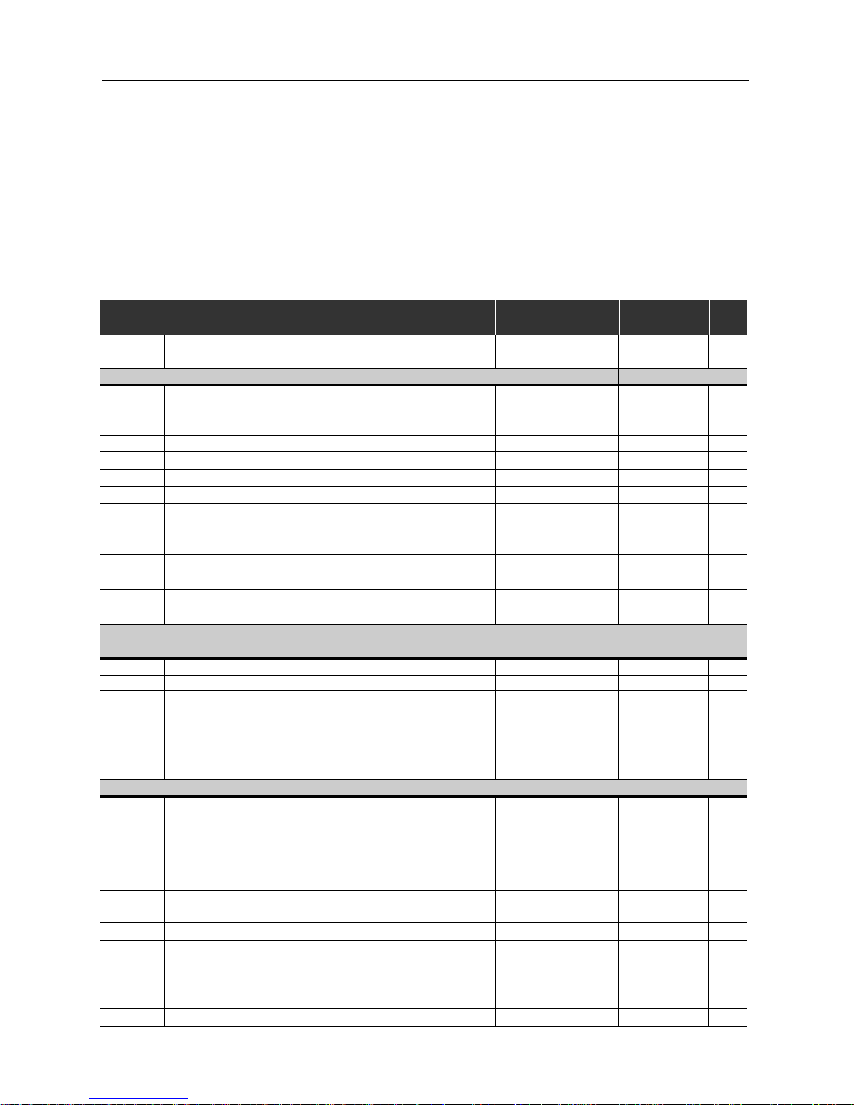
Revision Description Section
1 First Edition 2 Item 3.3 - CE Installation Included See item 3.3
3 General Revision -
4
External Parallel Keypad and
See item 8.3
Fixs Kit Included and
and 8.12
General Revision
5 General Revision -
6
Description changed of the Parallel Cable
See item 8.5
for the External Parallel Keypad.
and 6.3.5
Item 7.5 (Spare Part List) Removed.
Parameter 536 included
and General Revision
Page 4

CONTENTS
Quick Parameter Reference,
Fault and Status Messages
1 Parameters .................................................................................07
2 Fault Messages ..........................................................................14
3 Other Messages ......................................................................... 14
CHAPTER 1
Safety Notices
1.1 Safety Notices in the Manual .................................................15
1.2 Safety Notice on The Product ................................................15
1.3 Preliminary Recommendations...............................................15
CHAPTER 2
General Information
2.1 About this Manual..................................................................17
2.2 Version of Software ................................................................17
2.3 About the CFW-08 .................................................................18
2.3.1 Differences between the Old µline and the New CFW-0821
2.4 CFW-08 Identification ............................................................. 25
2.5 Receiving and Storing.............................................................27
CHAPTER 3
Installation
3.1 Mechanical Installation...........................................................28
3.1.1 Environment ..................................................................28
3.1.2 Mounting Specifications ................................................29
3.2 Electrical Installation ..............................................................32
3.2.1 Power/Grounding Connections ......................................32
3.2.2 Power T erminals............................................................35
3.2.3 Location of the Power/Grounding/Control Connections ..36
3.2.4 Control Wiring ...............................................................37
3.2.5 Typical Terminal Connections ........................................40
3.3 European EMC Directive ........................................................43
3.3.1 Installation .....................................................................43
3.3.2 Inverter Models and Filters .............................................44
3.3.3 EMC Categories Description.......................................... 46
3.3.4 EMC Categories Characteristics Filters .........................47
CHAPTER 4
Start-up
4.1 Pre-Power Checks .................................................................52
4.2 Initial Power-up ......................................................................52
4.3 Start-up .................................................................................. 53
4.3.1 Start-up Operation via Keypad (HMI)
Type of Control: Linear V/F (P202=0).............................53
4.3.2 Start-up Operation via T erminals -
Type of Control: Linear V/F (P202=0).............................55
4.3.3 Start-up - Operation via Keypad (HMI)
Type of Control: V ector (P202=2) ...................................56
Page 5

CONTENTS
CHAPTER 5
Keypad (HMI) Operation
5.1 Keypad (HMI) Description ........................................................ 60
5.2 Use of the Keypad (HMI) .......................................................... 61
5.2.1 Keypad Operation ........................................................... 62
5.2.2 Inverter Status ................................................................. 63
5.2.3 Read-Only V ariables........................................................ 63
5.2.4 Parameter Viewing and Programming.............................. 64
CHAPTER 6
Detailed Parameter Description
6.1 Symbols .................................................................................. 66
6.2 Introduction .............................................................................. 66
6.2.1 Control Modes................................................................. 66
6.2.2 V/F Control...................................................................... 66
6.2.3 Vector Control (VVC)....................................................... 67
6.2.4 Frequency Reference Sources ........................................ 67
6.2.5 Commands...................................................................... 70
6.2.6 Local/Remote Operation Modes ...................................... 70
6.3 Parameter Listing ..................................................................... 71
6.3.1 Access and Read Only Parameters - P000...P099.......... 72
6.3.2 Regulation Parameters - P100...P199 ............................. 73
6.3.3 Configuration Parameters - P200...P398.......................... 81
6.3.4 Motor Parameters - P399...P499................................... 101
6.3.5 Special Function Paramaters - P500...P599.................. 104
6.3.5.1 PID Introduction ............................................... 104
6.3.5.2 PÌD Description ................................................ 104
6.3.5.3 PID Start-up Guide ........................................... 106
CHAPTER 7
Diagnostics and Troubleshooting
7.1 Faults and Possible Causes ...................................................110
7.2 Troubleshooting.......................................................................112
7.3 Contacting WEG .....................................................................113
7.4 Preventive Maintenance...........................................................113
7.4.1 Cleaning Instructions......................................................114
CHAPTER 8
CFW-08 Options and Accessories
8.1 HMI-CFW08-P.........................................................................116
8.1.1 Instructions for Insertion - Removing of HMI-CFW08-P....117
8.2 TCL-CFW08 ............................................................................117
8.3 HMI-CFW08-RP ......................................................................117
8.3.1 HMI-CFW08-RP Installation............................................118
8.4 MIP-CFW08-RP ......................................................................118
8.5 CAB-RP-1, CAB-RP-2, CAB-RP-3, CAB-RP-5, CAB-RP-7.5,
CAB-RP-10 .............................................................................119
8.6 HMI-CFW08-RS ......................................................................119
8.6.1 HMI-CFW08-RS Installation........................................... 120
8.6.2 HMI-CFW08-RS Start-up ............................................... 120
8.6.3 Keypad Copy Function.................................................. 121
8.7 MIS-CFW08-RS ..................................................................... 121
Page 6

CONTENTS
8.8 CAB-RS-1, CAB-RS-2, CAB-RS-3, CAB-RS-5, CAB-RS-7.5
CAB-RS-10 ............................................................................ 121
8.9 KCS-CFW08.......................................................................... 122
8.9.1 Instruction and Removing Instructions for KCS-CFW08 12 3
8.10 KSD-CFW08.......................................................................... 123
8.1 1 KMD-CFW08-M1.................................................................... 124
8.12 KFIX-CFW08-M1, KFIX-CFW08-M2 ........................................ 125
8.13 KN1-CFW08-M1, KN1-CFW08-M2 ......................................... 126
8.14 MIW-02 .................................................................................. 126
8.15 RFI Filters.............................................................................. 127
8.16 Line Reactor .......................................................................... 128
8.16.1 Application Criteria ...................................................... 128
8.17 Load Reactor ......................................................................... 129
8.18 Dynamic Braking.................................................................... 131
8.18.1 Resistor Sizing............................................................ 131
8.18.2 Installation................................................................... 132
8.19 Serial Communication ............................................................ 133
8.19.1 Introduction ................................................................. 133
8.19.2 Interfaces Description.................................................. 134
8.19.2.1 RS-485........................................................... 134
8.19.2.2 RS-232........................................................... 136
8.19.3 Definitions ................................................................... 136
8.19.3.1 Used T erms.................................................... 136
8.19.3.2 Parameters/V ariables Resolution.................... 136
8.19.3.3 Character Format ........................................... 136
8.19.3.4 Protocol ......................................................... 137
8.19.3.4.1 Reading Message .......................... 137
8.19.3.4.2 Writing Message ........................... 138
8.19.3.5 Execution and Message Test ......................... 138
8.19.3.6 Message Sequence ....................................... 139
8.19.3.7 V araiables Code ....................................................... 139
8.19.4 Message Examples..................................................... 139
8.19.5 Variables and Errors of the Serial Communication ....... 140
8.19.5.1 Basic V ariables .............................................. 140
8.19.5.1.1 V00 (Code 00700) .......................... 140
8.19.5.1.2 V02 (Code 00702) .......................... 140
8.19.5.1.3 V03 (Code 00703) .......................... 141
8.19.5.1.4 V04 (Code 00704) .......................... 142
8.19.5.1.5 V05 (Code 00705) .......................... 142
8.19.5.1.6 Message Examples with
Basic Variables .............................................. 142
8.19.5.2 Parameters Related to the Serial Communication143
8.19.5.3 Errors Related to the Serial Communication ... 144
8.19.6 Times for Read/Write of Messages.............................. 144
8.19.7 Physical Connection of RS-232 and RS-485 Interface.. 145
8.20 Modbus-RTU ...................................................................... 146
8.20.1 Introduction in the Modbus-RTU Protocol..................... 146
8.20.1.1 Transmission Modes ...................................... 146
8.20.1.2 Message Structure in RTU Mode.................... 146
8.20.1.2.1 Address ......................................... 147
8.20.1.2.2 Code Function ............................... 147
8.20.1.2.3 Dat a Field...................................... 14 7
8.20.1.2.4 CRC............................................... 147
8.20.1.3 Time between messages.......................................... 148
8.20.2 Operation of the CFW-08 in the Modbus-RTU Network 14 8
8.20.2.1 Interface Description....................................... 148
8.20.2.1.1 RS-232 .......................................... 149
Page 7

CONTENTS
8.20.2.1.2 RS-485 .......................................... 149
8.20.2.2 Inverter Configuration in the
Modbus-RTU Network..................................... 149
8.20.2.2.1 Inverter address in the Network ...... 149
8.20.2.2.2 Transmission Rate and Parity ........ 149
8.20.2.3 Access to the Inverter Data ............................ 149
8.20.2.3.1Available Functions and
Response Times ............................................ 150
8.20.2.3.2 Register addressing and Offset ...... 150
8.20.3Detailed Function Description ...................................... 152
8.20.3.1 Function 01 - Read Coils ................................ 15 3
8.20.3.2 Function 03 - Read Holding Register .............. 153
8.20.3.3 Function 05 - Write Single Coil ....................... 154
8.20.3.4 Function 06 - Write Single Register ................ 155
8.20.3.5 Function 15 - Write Multiple Coils................... 15 5
8.20.3.6 Function 16 - Write Multiple Registers............ 15 6
8.20.3.7 Function 43 - Read Device Identification ......... 157
8.20.4Communication Errors ................................................. 159
8.20.4.1 Error Messages.............................................. 159
CHAPTER 9
Technical Specifications
9.1 Power Data ............................................................................ 161
9.1.1 200 - 240V Power Supply.............................................. 161
9.1.2 380 - 480V Power Supply.............................................. 161
9.2 General Electronic Data ......................................................... 163
9.3 WEG Standard IV Pole Motor Data ........................................ 164
CHAPTER 10
Warranty
Warranty Terms for Frequency Inverters - CFW-08 ........................ 165
Page 8
7
CFW-08 -
QUICK PARAMETER REFERENCE
Software: V3.9X
Application:
Model:
Serial Number:
Responsible:
Date: / / .
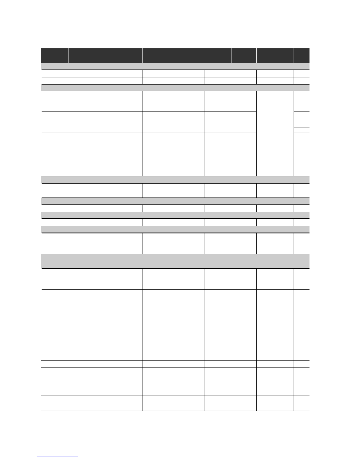
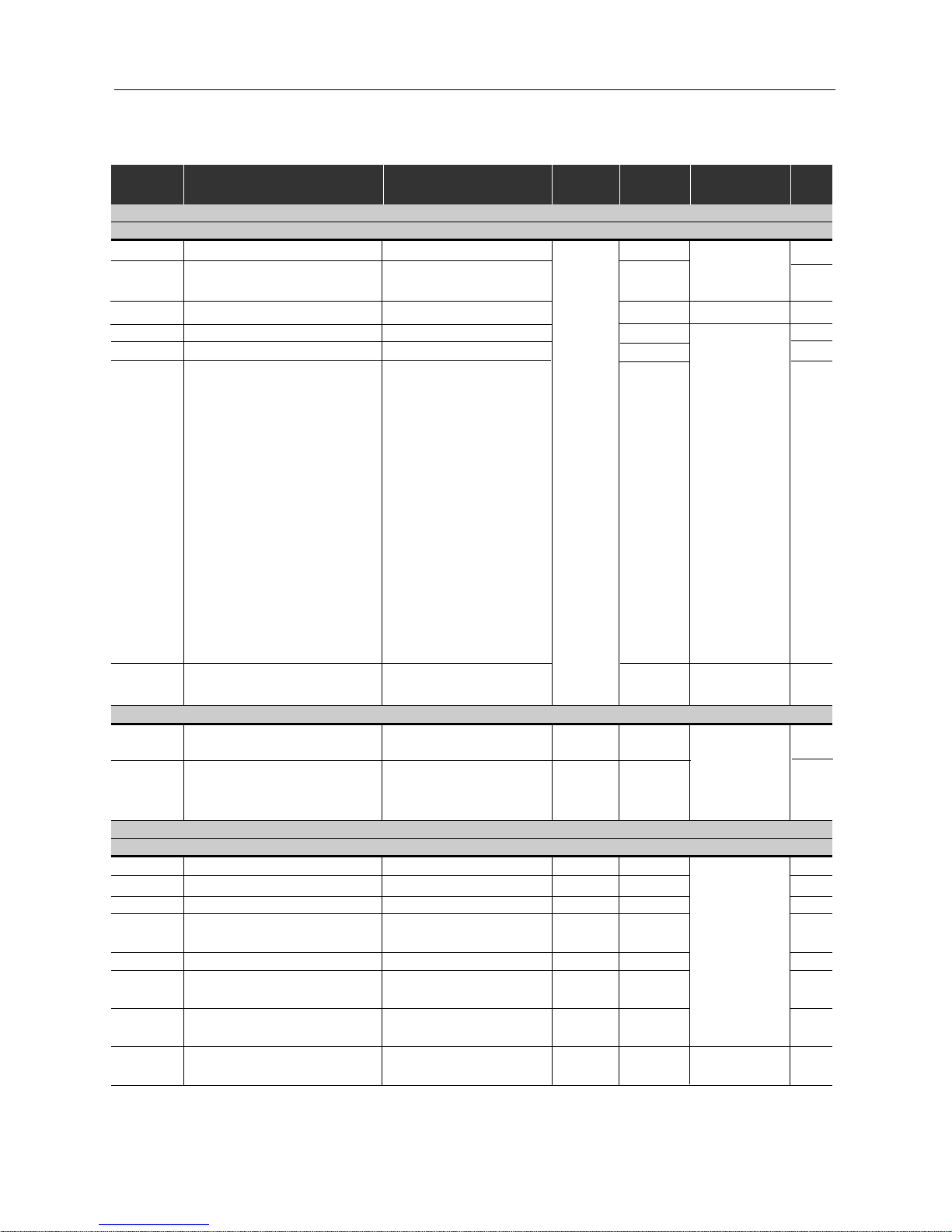
1. Parameters
Parameter Function
Adjustable Range
Factory User
Note Page
Setting Setting
P000 Parameter Access
0 ... 4, 6 ... 999 = Read
0- 72
5 = Alteration
READ ONL Y P ARAMETERS (P002 ... P099)
P002
Fequency Proportional Value
0 ... 6553 - - 72
(P208xP005)
P003 Motor Current 0 ... 1.5xI
nom
-- 72
P004 DC Link Voltage 0 ... 862V - - 72
P005 Motor Frequency 0.00 ... 99.99, 100.0 ... 300.0Hz - - 72
P007 Motor Voltage 0 ... 600V - - 72
P008 Heatsink Temperature 25 ... 110°C - - 72
P009 Motor Torque 0.0 ... 150.0% - -
Only avaliable
in vector control 72
mode (P202=2)
P014 Last Fault 00 ... 41 - - 72
P023 Software Version x . y z - - 73
P040
PID Process Variable
0 ... 6553 - - 73
(Value % x P528)
REGULATION PARAMETERS (P100 ... P199)
Ramps
P100 Acceleration Time #1 0.1 ... 999s 5.0 73
P101 Deceleration Time #1 0.1 ... 999s 10.0 73
P102 Acceleration Time #2 0.1 ... 999s 5.0 73
P103 Deceleration Time #2 0.1 ... 999s 10.0 73
P104
0 = Inactive
073
S Ramp 1 = 50%
2 = 100%
Frequency Reference
0 = Inactive
1 = Active 1 74
P120 Digital Reference Backup 2 = Backup by P121
(or P525 - PID)
P121 Keypad Reference P133 ... P134 3.00 74
P122 JOG Speed Reference 0.00 ... P134 5.00 74
P124 Multispeed Reference 1 P133 ... P134 3.00 75
P125 Multispeed Reference 2 P133 ... P134 10.00 75
P126 Multispeed Reference 3 P133 ... P134 20.00 75
P127 Multispeed Reference 4 P133 ... P134 30.00 75
P128 Multispeed Reference 5 P133 ... P134 40.00 75
P129 Multispeed Reference 6 P133 ... P134 50.00 75
P130 Multispeed Reference 7 P133 ... P134 60.00 75
P131 Multispeed Reference 8 P133 ... P134 66.00 75
QUICK P ARAMETER REFERENCE, F AUL T AND ST ATUS MESSAGES
Page 9
8
CFW-08 -
QUICK PARAMETER REFERENCE
Speed Limits
P133 Minimum Frequency (F
min
) 0.00 ... P134 3.00 7 6
P134 Maximum Frequency (F
max
) P133 ... 300.0Hz 66.00 76
V/F Control
P136
Manual Torque Boost
0.0 ... 30.0%
5.0 or
Only available
76
(IxR Compensation)
2.0 or
in V/F co n trol
1.0
(2)
Control Mode
P137
Aut. Torque Boost
0.00 ... 1.00 0.00
P202=0 or 1.
76
(aut. IxR compensation)
P138 Slip Compensation 0.0 ... 10.0% 0.0 77
P142
(1)
Maximum Output Voltage 0.0 ... 100% 100 78
P145
(1)
Field Weakening
P133 ... P134
50.00Hz or
78
Frequency (F
nom
)
60.00Hz
depending
on the
market
DC Link Volt age Regulation
P151 DC Link Regulation Level
200V models: 325 ... 410V 380V
79
400V models: 564 ... 820V 780V
Overload Current
P156 Motor Overload Current 0.2xI
nom
... 1.3xI
nom
1.2xP401 79
Current Limitation
P169 Maximum Output Current 0.2xI
nom
... 2.0xI
nom
1.5xI
nom
80
Flux Control
P178 50.0 ... 150% 100
Only available
80
Rated Flux in V/F control
mode (P202=2).
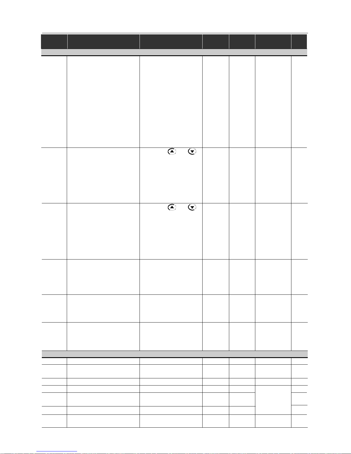
CONFIGURATION PARAMETERS (P200 ... P398)
Generic Parameters
P202
(1)
Control Mode
0 = Linear V/F Control
081
1 = Quadratic V/F Control
2 = Sensorless Vector
P203
(1)
Special Function Selection
0 = No function
082
1 = PID Regulator
P204
(1)
Load Factory Setting
0 ... 4 = No Function
0- 82
5 = Loads Factory Default
P205 Display Default Selection
0 = P005
282
1 = P003
2 = P002
3 = P007
4, 5 = Not used
6 = P040
P206 Auto-Reset Time 0 ... 255s 0 82
P208 Reference Scale Factor 0.00 ... 99.9 1.00 83
0 = Off
0
Only available
83
P215
(1)
Keypad Copy Function 1 = Copy (inverter to keypad) via HMI-CFW08-RS
2 = Paste (keypad to inverter) keypad.
P219
(1)
Switching Frequency
0.00 ... 25.00Hz 6.00 84
Reduction Point
(1)
This parameter can be changed only with the inverter disabled (motor stopped).
(2)
The factory default of Parameter P136 depends on the inverter model as follows:
- models 1.6-2.6-4.0-7.0A/200-240V or 1.0-1.6-2.6-4.0A/380-480V: P136=5.0%;
- models 7.3-10-16A/200-240V or 2.7-4.3-6.5-10A/380-480V: P136=2.0%;
- models 13-16A/380-480V: P136=1.0%.
Parameter Function
Adjustable Range
Factory User
Note Page
Setting Setting
Page 10
9
CFW-08 -
QUICK PARAMETER REFERENCE
(1)
This parameter can be changed only with the inverter disabled (motor stopped).
Only available
in CFW-08
Plus Version
Local/Remote Definition
P220
(1)
Local/Remote
0 = Always Local
285
Selection Source
1 = Always Remote
2 = HMI-CFW08-P or
HMI-CFW08-RP keypad
(default: local)
3 = HMI-CFW08-P or
HMI-CFW08-RP keypad
(default: remote)
4 = DI2 ... DI4
5 = Serial or HMI-CFW08-RS
keypad (default: local)
6 = Serial or HMI-CFW08-RS
keypad (default: remote)
0 = Keypad and
86
1 = AI1
2, 3 = AI2
P221
(1)
Local Reference Selection 4 = E.P. (Electronic Pot.)
0
5 = Serial
6 = Multispeed
7 = Add AI>=0
8 = Add AI
0 =Keypad and
86
1 = AI1
2, 3 = AI2
P222
(1)
Remote Reference Selection 4 = E.P. (Eletronic Pot.)
1
5 = Serial
6 = Multispeed
7 = Add AI>=0
8 = Add AI
0 = HMI-CFW08-P or
86
P229
(1)
Local Command Selection HMI-CFW08-RP keypad
1 = Terminals
0
2 = Serial or HMI-CFW08-RS
keypad
0 = HMI-CFW08-P or
86
P230
(1)
Remote Command Selection HMI-CFW08-RP keypad
1 = Terminals
1
2 = Serial or
HMI-CFW08-RS keypad
P231
(1)
Forward/Reverse Selection
0 = Forward
86
1 = Reverse 2
2 = Commands
Analog Input(s)
P234 Analog Input A I1 Gain 0.00 ... 9.99 1.00 86
P235
(1)
Analog Input AI1 Signal
0 = 0-10V/0-20mA
0
87
1 = 4-20mA
P236 Analog Input AI1 Offset -120 ... 120% 0.0 8 8
P238 Analog Input A I2 Gain 0.00 ... 9.99 1.00 88
P239
(1)
Analog Input AI2 Gain
0 = 0-10V/0-20mA
0
87
1 = 4-20mA
P240 Analog Input AI2 Offset -120 ... 120% 0.0 8 8
P248
Analog Inputs Filter
0 ... 200ms 20 0 8 8
Time Constant
Parameter Function
Adjustable Range
Factory User
Note Page
Setting Setting
Page 11

10
CFW-08 -
QUICK PARAMETER REFERENCE
Only available
in CFW-08
Plus version.
Analog Output
0 = Output Frequency (Fs)
1 = Input Reference (Fe)
2 = Output Current (Is)
3, 5, 8 = Not used 88
P251 Analog Output 4 = Motor Torque 0
AO Function 6 = Process Variable
(PID)
7 = Active Current
9 = PID Setpoint
P252 Analog Output AO Gain 0.00 ... 9.99 1.00 88
Digital Inputs
P263
(1)
Digital Input DI1 Function
0 = No Function or
089
General Enable
1 ... 7 and 10 ... 12 =
General Enable
8 = Forward Run
9 = Start/S top
13 = FWD Run Using
Ramp #2
14 = Start (3-wire)
P264
(1)
Digital Input DI2 Function
0 = Forward/Reverse
089
1 = Local/Remote
2 ... 6 and 9 ... 12 = Not used
7 = Multispeed (MS2)
8 = Reverse
13 = REV Run - Ramp #2
14 = Stop (3-wire)
P265
(1) (2)
Digital Input DI3 Function
0 = Forward/Reverse
10 89
1 = Local/Remote
2 = General Enable
3 = JOG
4 = No External Fault
5 = Increase E.P.
6 = Ramp #2
7 = Multispeed (MS1)
8 = No Function or
Start/Stop
9 = Start/S top
10 = Reset
11, 12 = Not used
13 = Flying Start Disable
14 = Multispeed (MS1)
Using Ramp #2
15 = Manual/Automatic PID)
16 = Increase E.P. with
Ramp #2
P266
(1)
Digital Input DI4 Function
0 = Forward/Reverse
889
1 = Local/Remote
2 = General Enable
(1)
This parameter can be changed only with the inverter disabled (motor stopped).
(2)
Value may change as a function of P203.
Parameter Function
Adjustable Range
Factory User
Note Page
Setting Setting
Page 12

11
CFW-08 -
QUICK PARAMETER REFERENCE
According
to the
inverter
model
Only available
in CFW-08
Plus version.
In vector control
mode (P202=2)
it is not possible
to set P297=7
(15kHz).
3 = JOG
4 = No Extrernal Fault
5 = Decrease E.P.
6 = Ramp #2
7 = Multispeed (MS0)
8 = Not used or
Start/Stop
9 = Start/S top
10 = Reset
11, 12, 14 and 15 =
Not Used
13 = Flying Start Disable
16 = Decrease E.P. with
Ramp #2
Digital Output(s)
P277
(1)
Relay Output RL1 Function
0 = Fs>Fx
794
1 = Fe>Fx
2 = Fs=Fe
3 = Is>Ix
4 and 6 = Not used
5 = Run
7 = No Fault
P279
(1)
Relay Output RL2 Function
0 = Fs>Fx
0
94
1 = Fe>Fx
2 = Fs=Fe
3 = Is>Ix
4 and 6 = Not used
5 = Run
7 = No Fault
Fx and Ix
P288 Fx Frquency 0.00 ... P134 3.00 95
P290 Ix Current 0 ... 1.5xI
nom
1.0xI
nom
95
Inverter Data
P295
(1)
Rated Inverter
300 = 1.0A
95
Current (I
nom
)
301 = 1.6A
302 = 2.6A
303 = 2.7A
304 = 4.0A
305 = 4.3A
306 = 6.5A
307 = 7.0A
308 = 7.3A
309 = 10A
310 = 13A
311 = 16A
P297
(1)
Switching Frequency
4 = 5.0kHz
4
96
5 = 2.5kHz
6 = 10kHz
7 = 15kHz
DC Braking
P300 DC Braking Time 0.0 ... 15.0s 0.0 9 7
Parameter Function
Adjustable Range
Factory User
Note Page
Setting Setting
(1)
This parameter can be changed only with the inverter disabled (motor stopped).
Page 13

12
CFW-08 -
QUICK PARAMETER REFERENCE
Serial Communication Interface I
P308
(1)
Inverter Address
1 ... 30 (Serial WEG)
198
1 ... 247 (Modbus-RTU)
Flying Start and Ride-Through
P310
(1)
Flying Start and Ride-Through
0 = Inactive
099
1 = Flying Start
2 = Flying Start and
Ride-Through
3 = Ride-Through
P311 Voltage Ramp 0.1 ... 10.0s 5.0 100
Serial Communication Interface II
P312
(1)
Serial Interface Protocol
0 = Serial WEG
0 100
1 = Modbus-RTU 9600 bps
without parity
2 = Modbus-RTU 9600 bps
with odd parity
3 = Modbus-RTU 9600 bps
with even parity
4 = Modbus-RTU 19200 bps
without parity
5 = Modbus-RTU 19200 bps
with odd parity
6 = Modbus-RTU 19200 bps
with even parity
7 = Modbus-RTU 38400 bps
without parity
8 = Modbus-RTU 38400 bps
with odd parity
9 = Modbus-RTU 38400 bps
with even parity
P313
Serial Interface Watchdog
0 = Desabling by ramp
2 100
Action
1 = General disable
2 = Shows only E28
3 = Goes to local mode
P314
Serial Interface Watchdog 0.0 = Desables the function
0.0 100
Timeout 0.1 ...99.9s = Set value
(1)
This parameter can be changed only with the inverter disabled (motor stopped).
Parameter Function
Adjustable Range
Factory User
Note Page
Setting Setting
P301
DC Braking Start
0.00 ... 15.00Hz 1.00 97
Frequency
P302
DC Braking
0.0 ... 130% 0.0 97
Current
Skip Frequencies
P303 Skip Frequency 1 P133 ... P134 20.00 98
P304 Skip Frequency 2 P133 ... P134 30.00 98
P306 Skip Band Range 0.00 ... 25.00Hz 0.00 9 8
Page 14
13
CFW-08 -
QUICK PARAMETER REFERENCE
Only available in
vector mode
(P202=2).
Only available
in vector mode
(P202=2).
Only available
in vector mode
(P202=2).
According
to inverter
model
(1)
This parameter can be changed only with the inverter disabled (motor stopped).
MOTOR P ARAMETERS (P399 ... P499)
Rated Parameters
P399
(1)
Rated Motor Efficiency 50.0 ... 99.9% 101
P400
(1)
Rated Motor Voltage
0 ... 600V 101
P401 Rated Motor Current 0.3xI
nom
... 1.3xI
nom
101
P402 Rated Motor Speed 0 ... 9999rpm 10 1
P403
(1)
Rated Motor Frequency 0.00 ... P134 101
P404
(1)
Rated Motor Power
0 = 0.16HP / 0.12kW
1 = 0.25HP / 0.18kW
2 = 0.33HP / 0.25kW
3 = 0.50HP / 0.37kW
4 = 0.75HP / 0.55kW
5 = 1HP / 0.75kW 102
6 = 1.5HP / 1.1kW
7 = 2HP / 1.5kW
8 = 3HP / 2.2kW
9 = 4HP / 3.0kW
10 = 5HP / 3.7kW
11 = 5.5HP / 4.0kW
12 = 6HP / 4.5kW
13 = 7.5HP / 5.5kW
14 = 10HP / 7.5kW
15 = 12.5HP / 9.2kW
P407
(1)
Rated Motor Power
0.50 ... 0.99 102
Factor
Measured Parameters
P408
(1)
Self-Tuning
0 = No
0- 102
1 = Yes
P409 Motor Stator Resistance 0.00 ... 99.99Ω 103
SPECIAL FUNCTION (P500 ... P599)
PID Regulator
P520 PID Proportional Gain 0.000 ... 7.999 1.000 109
P521 PID Integral Gain 0.000 ... 9.999 1.000 10 9
P522 PID Differential Gain 0.000 ... 9.999 0.000 10 9
P525
Setpoint Via Keypad of the
0.00 ... 100.0% 0.00 109
PID Regulator
P526 Process Variable Filter 0.01 ... 10.00s 0.10 109
P527 PID Action
0 = Direct
0109
1 = Reverse
P528
Process Variable
0.00 ... 99.9 1.00 109
Scale Factor
P536 Automatic Setting of P525
0=Active
0109
1=Inactive
According
to inverter
model
(motor
matched
to the
inverter see item
9.3)
and sales
market
Parameter Function
Adjustable Range
Factory User
Note Page
Setting Setting
Page 15

14
CFW-08 -
QUICK PARAMETER REFERENCE
Display Description Page
E00 Output Overcurrent/Short-Circuit 110
E01 DC Link Overvoltage 110
E02 DC Link Undervoltage 110
E04 Inverter Overtemperature 111
E05 Output Overload (Ixt Function) 11 1
E06 External Fault 111
E08 CPU Error (Watchdog) 111
E09 Program Memory Error (Checksum) 111
E10 Keypad Copy Function Error 111
E14 Self-tuning Fault 111
E22, E25
Serial Communication Error 111
E26 and E27
E24 Programming Error 111
E28 Serial Interface Watchdog Timeout Error 111
E31 Keypad Connection Fault (HMI-CFW08-RS) 111
E41 Self-Diagnosis Fault 111
2. Fault Messages
3. Other Messages
Display Description
rdy Inverter is ready to be enabled
Sub
Power suplly voltage is too low for the inverter operation
(Undervoltage)
dcbr Inverter in DC braking mode
auto Inverter is running self-tuning routine
copy
Keypad Copy Function in Progress (only available in
the HMI-CFW08-RS) - inverter to keypad
past
Keypad Copy Function in Progress (only available in
the HMI-CFW08-RS) - Keypad to Inverter
Page 16
15
CHAPTER 1
SAFETY NOTICES
This Manual contains necessary information for the correct use of the
CFW-8 V ariable Frequency Drive.
This Manual has been written for qualified personnel with suitable training
and technical qualification to operate this type of equipment.
The following Safety Notices will be used in this Manual:
DANGER!
If the recommended Safety Notices are not strictly observed, it can lead
to serious or fatal injuries of personnel and/or material damage.
ATTENTION!
Failure to observe the recommended Safety Procedures can lead to
material damage.
NOTE!
The content of this Manual supplies important information for the correct
understanding of operation and proper performance of the equipment.
The following symbols may be attached to the product, serving as Safety
Notice:
High V olt ages
Components sensitive to electrostatic discharge. Do not touch them
without proper grounding procedures.
Mandatory connection to ground protection (PE)
Shield connection to ground
DANGER!
Only qualified personnel should plan or implement the installation,
start- up, operation and maintenance of this equipment. Personnel must
review entire Manual before attempting to install, operate or troubleshoot
the CFW-08.
DANGER!
The inverter control circuit (ECC2, DSP) and the HMI-CFW08-P are not
grounded. They are high voltage circuits.
1.3 PRELIMINARY
RECOMMENDATIONS
1.2 SAFETY NOTICE ON THE
PRODUCT
1.1 SAFETY NOTICES IN THE
MANUAL
Page 17

16
SAFETY NOTICES
These personnel must follow all safety instructions included in this Manual
and/or defined by local regulations.
Failure to comply with these instructions may result in personnel injury and/or
equipment damage.
NOTE!
In this Manual, qualified personnel are defined as people that are trained to:
1. Install, ground, power up and operate the CFW-08 according to this
Manual and the local required safety procedures;
2. Use of safety equipment according to the local regulations;
3. Administer Cardio Pulmonary Resuscitation (CPR) and First Aid.
DANGER!
Always disconnect the supply voltage before touching any electrical component
inside the inverter.
Many components are charged with high voltages, even after the incoming AC
power supply has been disconnected or switched OFF. Wait at least 10
minutes for the total discharge of the power capacitors.
Always connect the frame of the equipment to the ground (PE) at the suitable
connection point.
ATTENTION!
All electronic boards have components that are sensitive to electrostatic
discharges. Never touch any of the electrical components or connectors without
following proper grounding procedures. If necessary to do so, touch the properly
grounded metallic frame or use a suitable ground strap.
NOTE!
Inverters can interfere with other electronic equipment. In order to reduce this
interference, adopt the measures recommended in Section 3 “Installation”.
NOTE!
Read this entire Manual carefully and completely before installing or operating
the CFW-08.
Do not apply High V oltage (High Pot) Test on the Inverter!
If this test is necessary, contact the Manufacturer.
Page 18

CHAPTER 2
GENERAL INFORMA TION
This chapter defines the contents and purposes of this manual and
describes the main characteristics of the CFW-08 frequency inverter.
Identification, receiving inspections and storage requirements are also
provided.
2.1 ABOUT THIS MANUAL
This Manual is divided into 10 Chapter, providing infornation to the user on
how receive, install, start-up and operate the CFW-08:
Chapter 1 - Safety Notices;
Chapter 2 - General Information;
Chapter 3 - Installation;
Chapter 4 - Start-up;
Chapter 5 - Keypad HMI) Operation;
Chapter 6 - Detailed Parameter Description;
Chapter 7 - Diagnostic and Troubleshooting;
Chapter 8 - CFW-08 Options and Accessories;
Chapter 9 - Technical S pecifications;
Chapter 10 - Warranty Policy.
This Manual provides information for the correct use of the CFW-08. The
CFW-08 is very flexible and allows for the operation in many different
modes as described in this manual.
As the CFW-08 can be applied in several ways, it is impossible to describe
here all of the application possibilities. WEG does not accept any
responsibility when the CFW-08 is not used according to this Manual.
No part of this Manual may be reproduced in any form, without the written
permission of WEG.
2.2 SOFTWARE VERSION
It is important to note the Software V ersion installed in the V ersion CFW08, since it defines the functions and the programming parameters of the
inverter.
This Manual refers to the Software version indicated on the inside cover.
For example, the Version 3.0X applies to versions 3.00 to 3.09, where “X”
is a variable that will change due to minor software revisions. The operation
of the CFW-08 with these software revisions are still covered by this version
of the Manual.
The Software V ersion can be read in the Parameter P023.
Page 19

18
GENERAL INFORMATION
2.3 ABOUT THE CFW-08
The CFW-08 is a high performance V ariable Frequency Drive that permits
the control of speed and torque of a three-phase AC induction motor . T wo
types of control are available in the same product:
Programmable scalar (Volts/Hz) control;
Sensorless Vector Control (VVC: V oltage V ector Control).
In the vector control mode, the motor performance is optimized relating to
torque and speed regulation.
The "Self-Tuning" function, available in vector control, permits the automatic
setting of the inverter parameter from the identification (also automatic) of
the parameters of the motor connected at the inverter output.
The V/F (scalar) mode is recommended for more simple applications
such as pump and fan drives. In these cases one can reduce the motor
and inverter losses by using the "Quadratic V/F" option, that results in
energy saving.
The V/F mode is also used when more than one motor should be driven
simultaneously by one inverter (multimotor application).
There are two CFW-08 versions:
Standard: it has 4 digit al inputs (DIs), 1 analog input (AI) and 1 relay
output.
CFW-08 Plus: compared to the standard version it has one additional
analog input and one additional relay output. It has also an analog
output (AO).
For power ratings and further technical information, see Chaper 9.
Page 20
19
GENERAL INFORMATION
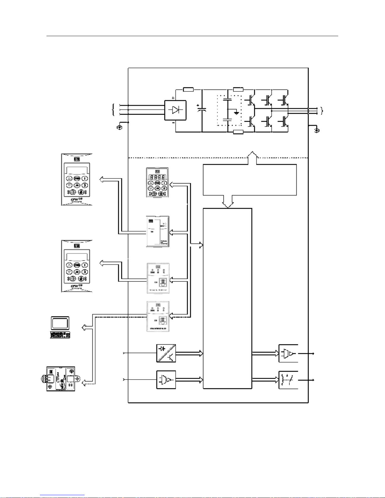
Figure 2.1 - Block diagram for the models:
1.6-2.6-4.0-7.0A/200-240V and 1.0-1.6-2.6-4.0A/380-480V
Power
Supply
R
S
T
P E
PC-Software
SuperDrive
or
RS-485
MIW-02
Analog
Inputs
(AI1 and
AI2)
Digital
Inputs
(DI1 to DI4)
POWER
CONTROL
POWER SUPPLIES AND
CONTROL / POWER INTERF ACES
"ECC2"
CONTROL BOARD
WITH DSP
Analog
Output
(AO)
Relay
Output
(RL1 and
RL2)
Motor
U
V
W
Rsh2
Rsh1
NTC
PE
RFI Filter
Interface
RS-232 KCS-CFW08
Interface
MIS-CFW08-RS
HMI-CFW08-P
Interface
MIP-CFW08-RP
or
or
or
HMI-CFW08-RS
HMI-CFW08-RP
Page 21
20
GENERAL INFORMATION
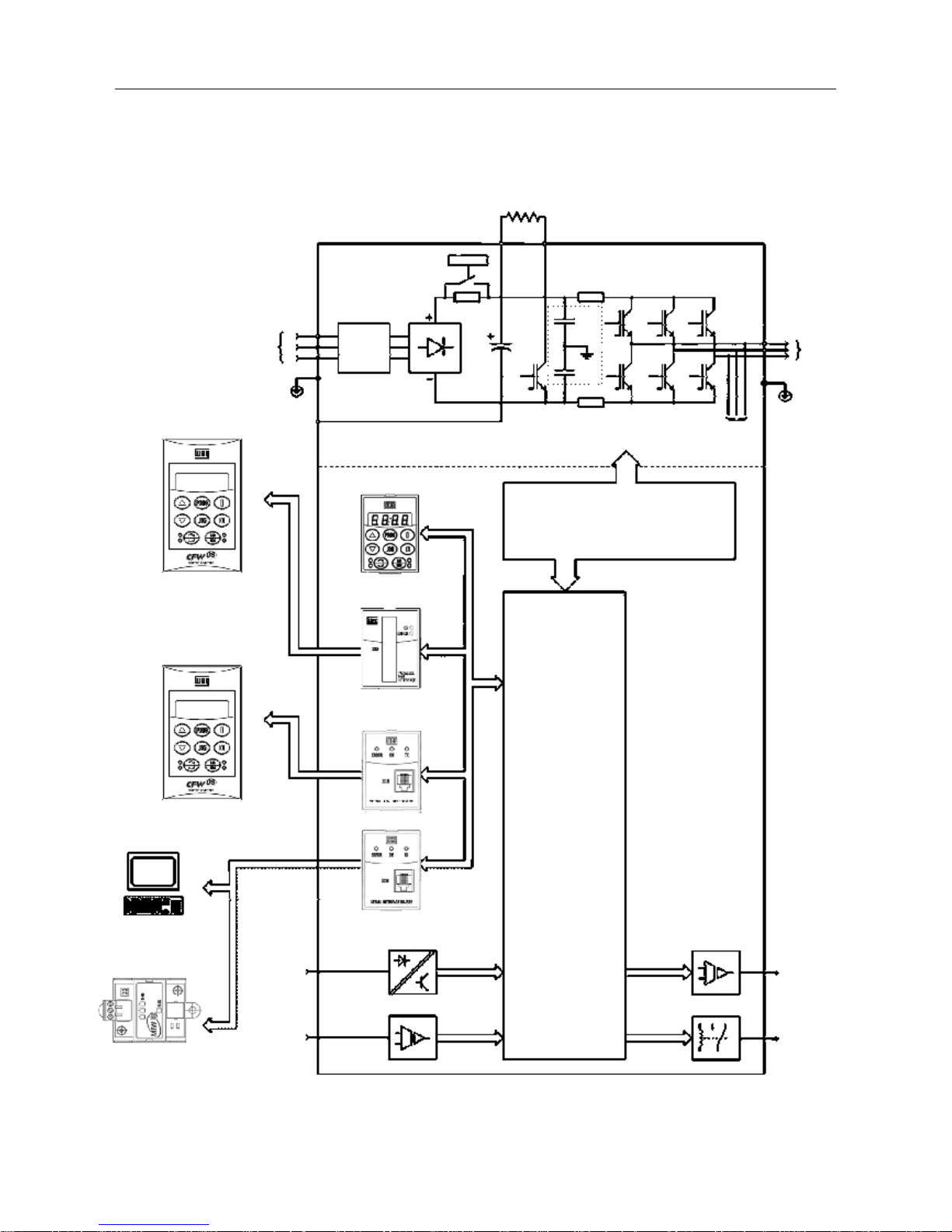
Figura 2.2– Block diagram for the models:
7.3-10-16A/200-240V and 2.7-4.3-6.5-10-13-16A/380-480V
Note: Model 16A/200-240V is not fitted with RFI filter (optional).
Power
Supply
R
S
T
RFI
Suppressor
Filter
(optional)
PC-Software
SuperDrive
or
RS-485
MIW-02
Analog
Inputs
(AI1 and AI2)
Digital
Inputs
(DI1 to DI4)
POWER
CONTROL
POWER SUPPLIES AND CONTROL /
POWER INTERFACES
"ECC2"
CONTROL BOARD
WITH DSP
Analog
Output
(AO)
Relay
Output
(RL1 and
RL2)
Motor
U
V
W
Rsh2
Rsh1
RPC
Pré-Carga
Braking
Resistor (External and Optional)
BR
+VD
PE
-UD
Voltage
Feedback
PE
RFI
Filter
HMI-CFW08-RS
HMI-CFW08-RP
Interface
RS-232 KCS-CFW08
Interface
MIS-CFW08-RS
HMI-CFW08-P
Interface
MIP-CFW08-RP
or
or
or
Page 22
21
GENERAL INFORMATION
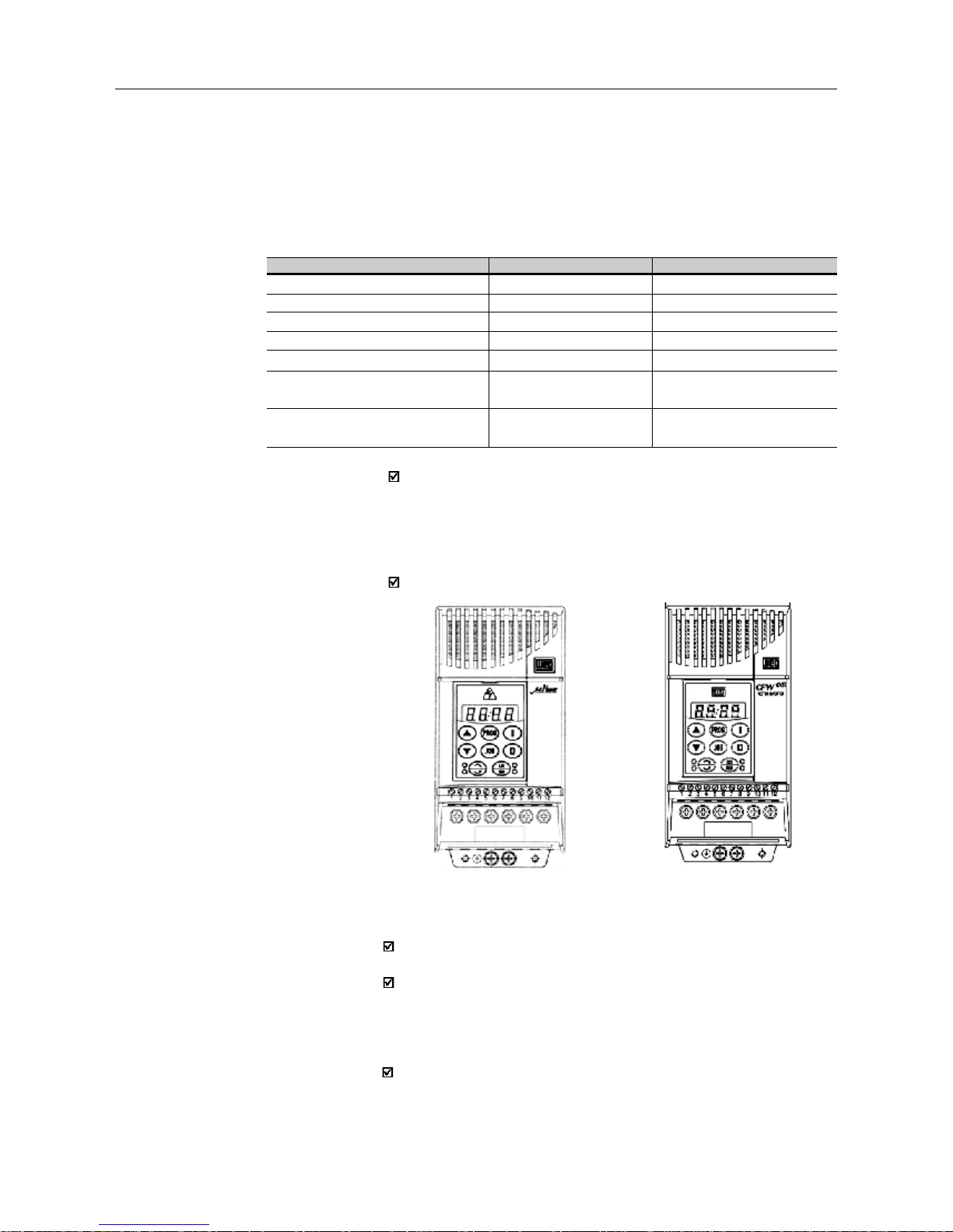
Product Appearance
Besides the internal electronics, also the exterrnal product appearance
have changed, which are:
- the frontal lettering on the plastic covers (formerly: µline, now:
CFW-08 vector inverter);
- WEG logo is now indicated on all accessories of the CFW-08 line
(keypad, communication modules etc).
Figure below makes a comparison:
2.3.1Differences between the
old
µ
line and
the new
CFW-08
(a)
µline
(b) CFW-08
Figure 2.3 - Comparison between µline a CFW-08 appearance
Version of Software
The new CFW-08 starts with Software V ersion V3.00. Thus, the software
Versions V1.xx and V2.xx are exclusive for µline.
Besides the inverter control has been implemented in a DSP (Digital
Signal Processor), which enables a more sophisticated control with
more parameters and functions.
Accessories
With the migration from the 16 bits microcontroller to the DSP of the
new CFW-08, the power supply of the electronic circuits had to be
changed from 5V to 3.3V . Consequently , the accesories (keyp ads,
communication modules, etc) of the old µline CAN NOT BE USED
with the new CFW-08 line. As general rule, use only accessories with
WEG logo, as already informed above.
This section aims at showing the differences between the old µline and
the new CFW-08. The information below are addressed to user that are
used to µline.
Table below shows the equivalence between the accessories of the old
µline an the new CFW-08.
Acessoriy
Local Keypad (parallel)
Remote serial Keypad
Remote parallel Keypad
Interface for remote serial Keypad
Interface for remote parallel Keypad
Interfaces for serial communication
RS-232
Interface for RS-485
serial communication RS-485
µline
IHM-8P (417100258)
IHM-8R (417100244)
-
MIR-8R (417100259)
-
MCW-01 (417100252)
MCW-02 (417100253)
CFW-08
HMI-CFW08-P (417100868)
HMI-CFW08-RS (417100992)
HMI-CFW08-RP (417100991)
MIS-CFW08-RS (417100993)
MIP-CFW08-RP (417100990)
KCS-CFW08 (417100882)
KCS-CFW08 (417100882) +
MIW-02 (417100543)
Page 23
22
GENERAL INFORMATION
Expansion of the Power Range
The power range of the old µline (0.25-2HP) has been expanded to
(0.25-10HP) with the new CFW-08 line.
Control Modes
Only the CFW-08 line has:
- Volt age Vector Control (VVC) that improves the inverter performance
considerably - adding the parameters P178, P399, P400, P402,
P403, P404, P407, P408 e P409;
- the quadratic curve V/F improves the systema energy saving capability
when loads with quadratic torque x speed characteristics are driven,
like pumps and fans.
Frequency Resolution
The new CFW-08 has a frequency resolution 10 times higher than the
old µline, i.e., it has a resoltion of 0.01Hz for frequencies up to 100.0Hz
and of 0.1Hz for frequencies higher than 99.99Hz.
Switching Frequencies of 10 and 15kHz
When the new CFW-08 is used, one can set the inverter switching
frequency to 10 and 15kHz, which enables an extremly quiet operation.
The audible noise level generated by the motor with 10 kHz is lower
with the CFW-08, when compared with the µline. This is due to the
PWM modulation improvements of the CFW-08.
Inputs and Outputs (I/Os)
The CFW-08 Plus line has more I/Os than the old µline, while the
CFW-08 is equivalent to the µline in terms of of I/Os. See table below:
I/O
Digital Inputs
Analog Input(s)
Analog Outputs
Relay Outputs
µline
4
1
-
1
(REV contatct)
CFW-08
4
1
-
1
(REV contact)
CFW-08 Plus
4
2
1
2 (1 NO contact,
1 NC contact)
Page 24
23
GENERAL INFORMATION
I/O
Digital Input DI1
Digital Input DI2
Digital Input DI3
Digital Input DI4
0V for Digital Inputs
+10V
Analog Input AI1 voltage signal
Analog Input AI1 current signal
0V for analog
input(s)
Analog Input AI2 voltage signal
Analog Input AI2 current signal
Saída Analógica AO
Relay Ouput RL1
Relay Output RL2
µline
1
2
3
4
5
6
7
9
8
not
available
not
available
not
availablel
10(NF), 11(C)
and 12(NA)
not
available
CFW-08
1
2
3
4
5
6
7 with switch
S1:1 at pos. OFF
7 with switch
S1:1 at pos. ON
5
not
available
not
available
not
available
10(NF), 11(C)
and 12(NA)
not
available
CFW-08 Plus
1
2
3
4
5
6
7 with switch S1:1
at position OFF
7 with switch S1:1
at position ON
5
8 with switch S1:2
at position OFF
8 with switch S1:2
at position ON
9
11-12(NO)
10-11(NC)
Parameters and Functions
Parameters that are already used in
µµ
µµ
µline but have been changed
a) P136 - Manual T orque Boost (IxR Compensation)
Besides the parameter name, also the way the user enters the IxR
compensation value has been changed. In the old µline, the
parameter P136 had a family of 10 curves (value range: 0 to
9). In the new CFW-08, the IxR Compensation is set by entering a
percent (relating to the input voltage) that defines the output voltage
for an output frequency equal to zero. So larger curve set and a
larger variation range is obtained.
T able below shows the equivalence between which was programmed
in the old µline and which must be programmed in the new CFW08 to obtain the same result.
P136 set in µline
0
1
2
3
4
5
6
7
8
9
P136 to be set in the CFW-08
0.0
2.5
5.0
7.5
10.0
12.5
15.0
17.5
20.0
22.5
But the control connections (terminals XC1) differ between the µline
and the CFW-08 line. T able below shows theses pin dif ferences:
Page 25

24
GENERAL INFORMATION
b) Automatic T orque Boost (Automatic IxR Compensation) and Slip
Compensation
In the µline only the rated motor current (P401) was used in
the Automatic IxR Compensation and the Slip Compensation
functions. In the µline the rated motor power factor of the motor
was considered as a fixed value and equal to 0.9 .
Now in the new CFW-08, are used the parameters P401 and P407
(rated motor power factor). Thus:
Example: When in an application with the µline the following setting
was required: P401=3.8A, now with the new CFW-08 you must perform
the following setting: P401=3.8A and P407=0.9
or
P407= rated cos ∅ of the used motor and P401=3.8 x
0.9
P407
Parameters existing only in Special Software Versions of the
µµ
µµ
µline
a) Quick Inputs
In the new CFW-08, the response time of the the digital inputs is
10ms (max.).
In addition, the minimum acceleration and deceleration time was
reduced from 0.2s (µline) to 0.1s (CFW-08). Besides the DC braking
process can be interrupted before it has been concluded, for
instance, when a new enabling is required.
b) Other changes
P120=2 - digital reference backup via P121 independently of the
reference source.
P265=14 - DI3: multispeed using ramp #2.
New Parameters and Functions
The reference 1 of the multispeed that was in Parameter P121 (in
µline) is now in Parameter P124 (in CFW-08).
The DC link regulation level (ramp holding) can now be
programmed in Parameter P151 - in the µline this level was fixed to
377V for the 200-240V line and 747V for the 380-480V line.
Also the programming way of Parameter P302 has changed. In the
µline P302 was related to the voltage applied to the output during the
D Cbraking, now in the new CFW-08, P302 defines the DC Braking
Current.
PID regulator.
Suammarizing, the new parameters are: P009, P040, P124, P151,
P178, P202, P203, P205, P219, P238, P239, P240, P251, P252, P279,
P399, P400, P402, P403, P404, P407, P408, P409, P520, P521, P522,
P525, P526, P527 e P528.
P401
uline
. 0.9 = P401 x P407
CFW-08
Page 26
25
GENERAL INFORMATION
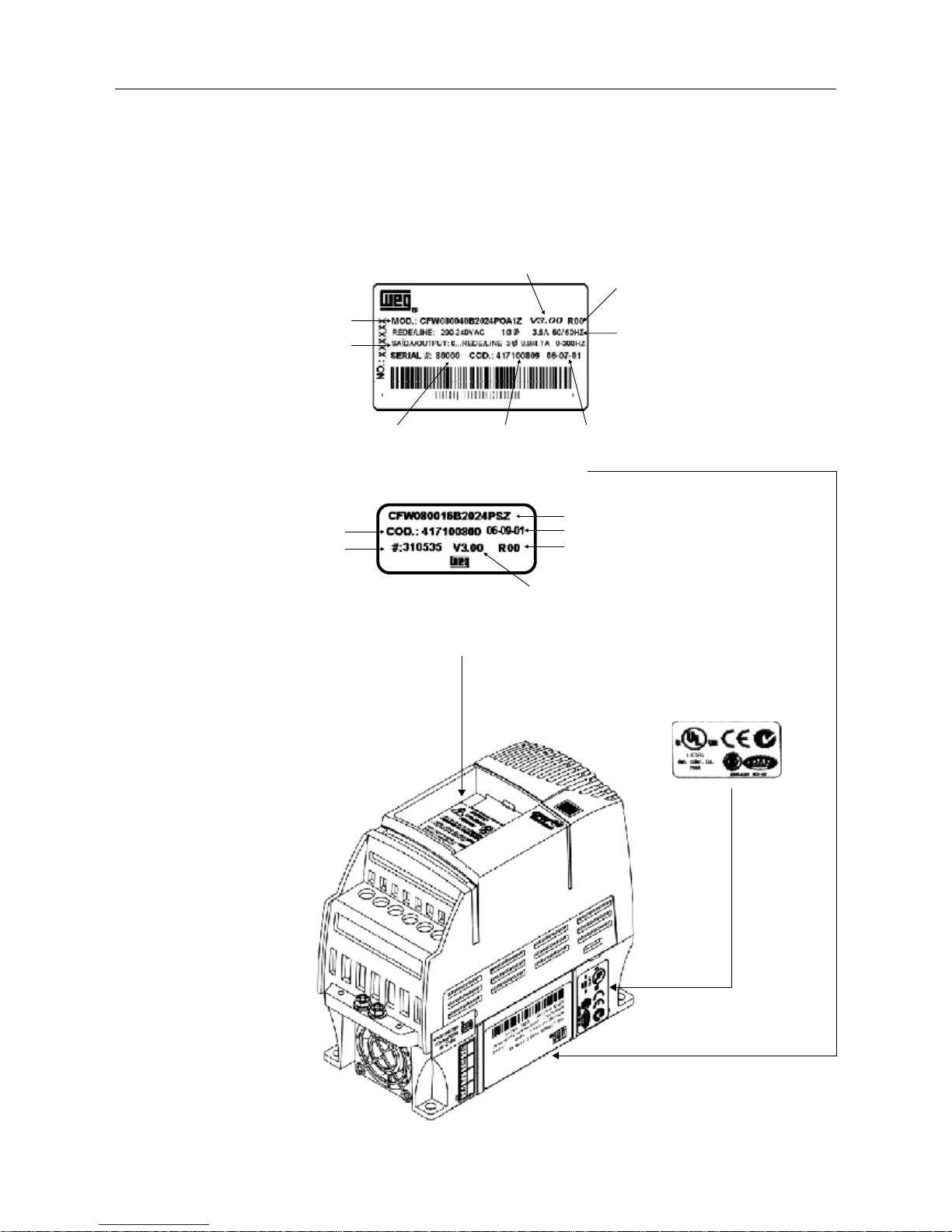
2.4 CFW-08 IDENTIFICA TION
Figure 2.4 - Description and location of the nameplates
Software
Version
Hardware
Revision
Rated Input Data
(Voltage, Number of
Phases Current,
Frequency)
Manufacturing DateWEG Part NumberSerial Number
CFW-08 Model
Rated Output Data
(Voltage, Frequency)
Lateral Nameplate of the CFW-08
Frontal Nameplate of the CFW-08 (under the keypad)
Note: T o remove the
keypad, see instructions
in 8.1.1 (Figure 8.2).
WEG Part Number
Seriel Number
CFW-08-Model
Manufacturing Date
Hardware Revision
Software Version
Page 27

26
GENERAL INFORMATION
CFW-08 0040 B 2024 P O 00 00 00 00 00 00 Z
Rated Output
Current for
200 to 240V:
0016=1.6A
0026=2.6A
0040=4.0A
0070=7.0A
0073=7.3A
0100=10A
0160=16A
380 to 480V:
0010=1.0A
0016=1.6A
0026=2.6A
0027=2.7A
0040=4.0A
0043=4.3A
0065=6.5A
0100=10A
0130=13A
0160=16A
Number of
phases of
the power
supply:
S=single
phase
T=three
phase
B=single
phase or
three phase
Manual
Language:
P= Portug.
E= English
S= Spanish
F= French
G= German
Power
Supply:
2024 =
200 to 240V
3848 =
380 to 480V
Options:
S= standard
O= with
optiions
Degree of
Protection:
Blank =
standard
N1= Nema 1
Human
Machine
Interface:
blank
standard
SI= without
interface
(with dummy
panel)
WEG
Series 08
Frequency
Inverter
Control Board:
Blank =
standard
control
A1= control 1
(Plus Version)
Special
Software:
00 = none
End Code
RFI Filter:
Blank=
without
filter
FA=
Class A
RF I filter
(internal or
footprint)
Special
Hardware:
00 = none
HOW TO SPECIFY THE CFW-08 MODEL:
Page 28

27
GENERAL INFORMATION
2.5 Receiving and
Storing
NOTE!
The Option field (S or O) defines if the CFW-08 is a standard version or
if it will be equipped with any optional devices. If the standard version
is required, the specification code ends here.
The model number has always the letter Z at the end. For example:
CFW080040S2024ESZ = standard 4.0A CFW-08 inverter, single-phase
at 200...240V input with manual in English.
For the effect of this code, the standard product is conceived as follows:
- CFW-08 with standard control board.
- Degree of protection: NEMA 1 for the models 13 and 16A/380-480V;
IP20 for the other models.
If the CFW-08 is equipped with any optional devices, you must fill out
all fields in the correct sequence up to the last optional device, the
model number is completed with the letter Z. It is not necessary to
indicate the code number 00 for those optional devices that are standard
or that will not be used.
Thus, for instance if the product above is required with NEMA 1 degree
of protection:
CFW080040S2024EON1Z = CFW-08 inverter, 4A, single-phase,
200...240V input, with manual in English language and with kitf fo r
NEMA 1 degree of protection.
The CFW-08 Plus is formed by the inverter and the control board 1.
Example: CFW080040S2024EOA1Z.
7.0 and 16.0A/200-240V and for all 380-480V models are just available
with three-phase power supply.
A RFI Class A filter (optional) can be installed inside the inverter in
models 7.3 and 10A/200-240V (single-phase) and 2.7, 4.3, 6.5, 10, 13
and 16A/380-480V . Models 1.6, 2.6 and 4.0A/200-240V (single-phase)
and 1.0, 1.6, 2.6 and 4.0A/380-480V can be provided mounted on a
footprint RFI Class A filter (optional).
The listing of the existing models (voltage/current) is shown in item 9.1.
The CFW-08 is supplied in cardboard boxes.
The outside of the packing box has a nameplate that is identical to that
on the CFW-08.
Please check if the CFW-08 is the one you ordered.
Check if the:
CFW-08 nameplate data matches with your purchase order .
The equipment has not been damaged during transport.
If any problem is detected, contact the carrier immedately .
If the CFW-08 is not installed immediately, store it in a clean and dry
room (storage temperatures between –25°C and 60°C). Cover it to
protect it against dust, dirt or other contamination.
Page 29

28
CHAPTER 3
INST ALLATION
3.1 MECHANICAL
INST ALLA TION
This chapter describes the procedures for the electrical and mechanical
installation of the CFW-08.
These guidelines and suggestions must be followed for proper CFW-08
operation.
3.1.1 Environment
The location of the inverter installation is an important factor to assure
good performance and high product reliability . For proper installation, we
make the following recommendations:
Avoid direct exposure to sunlight, rain, high moisture and sea air .
Avoid exposure to gases or explosive or corrosive liquids;
Avoid exposure to excessive vibration, dust, oil or any conductive
particles or materials.
Environmental Conditions:
T emperature : 32...104ºF (0 ... 40ºC) - nominal conditions. 32...122ºF
(0 ... 50ºC) - with 2% current derating for each 1.8ºF (1ºC) degree
above 104ºF (40ºC).
Relative Air Humidity: 5% to 90% - non-condensing.
Maximum Altitude: 3,300 f t (1000m) - nominal conditions.
3,300...13,200 ft (1000 ... 4000m) - with 10% current reduction for
each 3,300 ft (1000m) above 3,300 ft (1000m).
Pollution Degree: 2 (according to EN50178 and UL508C)
NOTE!
When inverters are installed in panels or in closed metallic boxes, adequate
cooling is required to ensure that the temperature arounds the inverter will
not exceed the maximim allowed temperature. See Dissipated Power in
Section 9.1.
Page 30
29
INSTALLATION AND CONNECTION
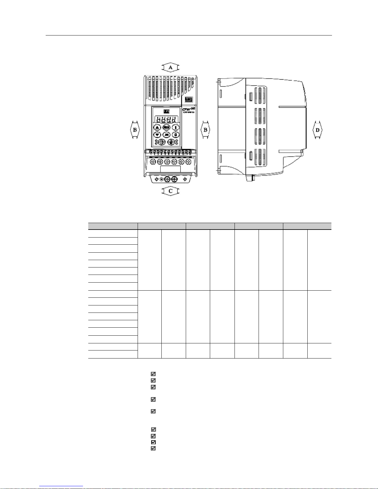
Table 3.1 - Recommended free spaces
Install the inverter in vertical position.
Leave free space around the inverter as indicated in T able 3.1.
Do not install heat sensitive components immediately above the
inverter.
When inverters are installed side by side, maintain the minimum
recommended distance B.
When inverters are installed top and bottom, maintain the minimum
recommended distance A + C and deflect the hot air coming from
the inverter below.
Install the inverter on a flat surface.
External dimensions and mounting holes are according to Fig. 3.2.
For CFW-08 installation procedures, see Fig. 3.3.
Provide independent conduits for signal, control and power
conductors. (Refer to Electrical Installation). Separate the motor
cables from the other cables.
CFW-08 Model
1.6A / 200-240V
2.6A / 200-240V
4.0A / 200-240V
7.0A / 200-240V
1.0A / 380-480V
1.6A / 380-480V
2.6A / 380-480V
4.0A / 380-480V
7.3A / 200-240V
10.0A / 200-240V
16.0A / 200-240V
2.7A / 380-480V
4.3A / 380-480V
6.5A / 380-480V
10.0A / 380-480V
13.0A / 380-480V
16.0A / 380-480V
ABCD
30 mm 1.18 in 5 mm 0.20 in 5 0 mm 2 in 50 mm 2 in
35 mm 1.38 in 15 mm 0.59 in 5 0 mm 2 in 50 mm 2 in
40 mm 1.57 in 30 mm 1.18 in 5 0 mm 2 in 50 mm 2 in
3.1.2 Mounting Specification
Figure 3.1 - Free Space for Cooling
Page 31

30
INSTALLATION AND CONNECTION
Figure 3.2 - Dimensional Drawings of the CFW-08
VIEW OF THE
MOUNTING BASE
FRONTAL
VIEW
LATERAL VIEW
Page 32

31
INSTALLATION AND CONNECTION
Inverter
Model
1.6A / 200-240V
2.6A / 200-240V
4.0A / 200-240V
7.0A / 200-240V
7.3A / 200-240V
10A / 200-240V
16A / 200-240V
1.0A / 380-480V
1.6A / 380-480V
2.6A / 380-480V
2.7A / 380-480V
4.0A / 380-480V
4.3A / 380-480V
6.5A / 380-480V
10A / 380-480V
13A / 380-480V
16A / 380-480V
Width L
in
(mm)
2.95
(75)
2.95
(75)
2.95
(75)
2.95
(75)
4.53
(115)
4.53
(115)
4.53
(115)
2.95
(75)
2.95
(75)
2.95
(75)
4.53
(115)
2.95
(75)
4.53
(115)
4.53
(115)
4.53
(115)
5.63
(143)
5.63
(143)
Height H
in
(mm)
5.95
(151)
5.95
(151)
5.95
(151)
5.95
(151)
7.87
(200)
7.87
(200)
7.87
(200)
5.95
(151)
5.95
(151)
5.95
(151)
7.87
(200)
5.95
(151)
7.87
(200)
7.87
(200)
7.87
(200)
7.99
(203)
7.99
(203)
Depth P
in
(mm)
5.16
(131)
5.16
(131)
5.16
(131)
5.16
(131)
5.91
(150)
5.91
(150)
5.91
(150)
5.16
(131)
5.16
(131)
5.16
(131)
5.91
(150)
5.16
(131)
5.91
(150)
5.91
(150)
5.91
(150)
6.50
(165)
6.50
(165)
A
in
(mm)
2.52
(64)
2.52
(64)
2.52
(64)
2.52
(64)
3.98
(101)
3.98
(101)
3.98
(101)
2.52
(64)
2.52
(64)
2.52
(64)
3.98
(101)
2.52
(64)
3.98
(101)
3.98
(101)
3.98
(101)
4.76
(121)
4.76
(121)
B
in
(mm)
5.08
(129)
5.08
(129)
5.08
(129)
5.08
(129)
6.97
(177)
6.97
(177)
6.97
(177)
5.08
(129)
5.08
(129)
5.08
(129)
6.97
(177)
5.08
(129)
6.97
(177)
6.97
(177)
6.97
(177)
7.09
(180)
7.09
(180)
C
in
(mm)
0.20
(5)
0.20
(5)
0.20
(5)
0.20
(5)
0.28
(7)
0.28
(7)
0.28
(7)
0.20
(5)
0.20
(5)
0.20
(5)
0.28
(7)
0.20
(5)
0.28
(7)
0.28
(7)
0.28
(7)
0.43
(11)
0.43
(11)
D
in
(mm)
0.24
(6)
0.24
(6)
0.24
(6)
0.24
(6)
0.20
(5)
0.20
(5)
0.20
(5)
0.24
(6)
0.24
(6)
0.24
(6)
0.20
(5)
0.24
(6)
0.20
(5)
0.20
(5)
0.20
(5)
0.39
(10)
0.39
(10)
Mounting
Screw
5/32
(M4)
5/32
(M4)
5/32
(M4)
5/32
(M4)
5/32
(M4)
5/32
(M4)
5/32
(M4)
5/32
(M4)
5/32
(M4)
5/32
(M4)
5/32
(M4)
5/32
(M4)
5/32
(M4)
5/32
(M4)
5/32
(M4)
3/16
(M5)
3/16
(M5)
Weigth
lb
(kg)
2.2
(1.0)
2.2
(1.0)
2.2
(1.0)
2.2
(1.0)
4.4
(2.0)
4.4
(2.0)
4.4
(2.0)
2.2
(1.0)
2.2
(1.0)
2.2
(1.0)
4.4
(2.0)
2.2
(1.0)
4.4
(2.0)
4.4
(2.0)
4.4
(2.0)
5.5
(2.5)
5.5
(2.5)
Degree of
Protection
IP20 / NEMA1
IP20 / NEMA1
IP20 / NEMA1
IP20 / NEMA1
IP20 / NEMA1
IP20 / NEMA1
IP20 / NEMA1
IP20 / NEMA1
IP20 / NEMA1
IP20 / NEMA1
IP20 / NEMA1
IP20 / NEMA1
IP20 / NEMA1
IP20 / NEMA1
IP20 / NEMA1
NEMA1
NEMA1
Dimensions Fixing base
Table 3.2 - Installation data (dimensions in mm) - Refer to Section 9.1
Figure 3.3 - Mounting procedures for CFW-08
AIR FLOW
Page 33

32
INSTALLATION AND CONNECTION
(a) Models 1.6-2.6-4.0-7.0A / 200-240V and 1.0-1.6-2.6-4.0A / 380-480V
PE
R
S
T
Power
Supply
Disconnect (*)
PE
T
Q1
R
S
TUVW
PE
PE WVU
DANGER!
AC input disconnection: provide and AC input disconnecting switch to
switch OFF the input power to the inverter.
This device shall disconnect the inverter from the AC input supply when
required (e.g. during maintenances services).
DANGER!
This AC input disconnecting switch can not be used as an emergency
stop device.
DANGER!
Be sure that the AC input power is disconnected before making any terminal connection.
DANGER!
The information below will be a guide to achieve a proper installation.Follow
also all applicable local standards for electrical installations.
ATENTION!
Provide at least 10 in (0.25m) spacing between the equipment and sensitive
wirings and betwen the cables of the inverter and motor. For instance:
PLCs, temperature monitoring devices, thermocouples, etc.
3.2 ELECTRICAL INST ALLA TION
3.2.1Power / Grounding
Connections
Page 34

33
INSTALLATION AND CONNECTION
NOTE!
Do not use the neutral conductor for grounding purposes.
Figure 3.5 - Grounding connections for more than one inverter
GROUNDING BAR
INTERNAL TO THE PANEL
DANGER!
The inverter must be grounded to a protective earth for safety purposes (PE).
The earth or ground connection must comply with the local regulations.For
grounding, use cables with cross sections as indicated in Table 3.3.
Make the ground connection to a grounding bar or to the general grounding
point (resistance 10 < ohms). Do not share the ground wiring with other
equipment that operate with high currents (for instance: high voltage
motors, welding machines, etc). If several inverters are used together,
refer to Figure 3.5.
Figure 3.4 - Power / Grounding Connections
(b) Models 7.3-10-16A / 200-240V e 2.7-4.3-6.5-10-13-16A / 380-480V
Note: (*) In case of single-phase power supply with phase and neutral cable, connect only the phase cable to the
disconnecting switch.
PE
R
S
T
Power
Supply
PE
T
Q1
RS
TUVW
PE
Shielding
PE W V
U
-UdBR
+Ud Braking
Resistor
(see item 8.17)
Disconnect (*)
Page 35

34
INSTALLATION AND CONNECTION
Table 3.3 - Recommended wiring and circuit-breakers - use 70ºC copper wires only
Amp
Rating
[ A ]
1.0
1.6 (200-240V)
1.6 (380-480V)
2.6 (200-240V)
2.6 (380-480V)
2.7
4.0 (200-240V)
4.0 (380-480V)
4.3
6.5
7.0
7.3
10.0
13.0
16.0
Power Cables
[ mm
2
]
1.5
1.5
1.5
1.5
1.5
1.5
1.5
1.5
1.5
2.5
2.5
2.5
2.5
2.5
2.5
Grounding Cables
[ mm
2
]
2.5
2.5
2.5
2.5
2.5
2.5
2.5
2.5
2.5
4.0
4.0
4.0
4.0
4.0
4.0
Current
[ A ]
4
10
4
10
6
6
15
10
10
15
10
20
30
30
35
WEG
Model
DMW25-4
DMW25-6,3
DMW25-4
DMW25-10
DMW25-6.3
DMW25-6.3
DMW25-16
DMW25-10
DMW25-10
DMW25-16
DMW25-10
DMW25-20
DW125H-32
DW125H-25
DW125H-32
Circuit-Breaker
ATTENTION!
The AC input for the inverter must have a grounded neutral conductor .
NOTE!
The AC input voltage must be comp atible with the inverter rated voltage.
The requirements for use of line reactors depends on several application
factors. Refer to Section 8.15.
Capacitors for power factor correction are not required at the input
(L/L1, N/L2, L3 or R, S, T ) and they must not be connected at the
output (U, V and W).
When inverters with dynamic braking (DB) are used, the DB resistor
shall be mounted externally . Figure 8.21 shows how to connect the
braking resistor. Size it according to the application, not exceeding
the maximum current of the braking circuit. For the connection between
inverter and the braking resistor, use twisted cable. Provide physical
separation between this cable and the signal and control cables. When
the DB resistor is mounted inside the panel, consider watt loss generated
when the enclosure size and required ventilation are calculated.
When electromagnetic interference (EMI), generated by the inverter,
interfers in the performance of other equipment, use shielded wires, or
install the motor wires in metallic conduits.Connect one end of the
shielding to the inverter grounding point and the other end to the motor
frame. Always ground the motor frame. Ground the motor in the p anel
where the inverter is installed or ground it to the inverter . The inverter
output wiring must be laid separately from the input wiring as well as
from the control and signal cables.
The inverter is provided with electronic protection against motor overload.
This protection must be set according to the specific motor. When the
same inverter drives several motors, use individual overload realays for
each motor. Maint ain the electrical continuity of the motor cable shield.
If a disconnect switch or a contactor is inserted in the motor supply
line, do not operate them with motor running or when inverter is enabled.
Maintain the electrical continuity of the motor cable shield.
Use wire sizing and circuit breakers as recommended in Table 3.3.
Tightening torque is as indicated in T able 3.4. Use (70ºC) copper wires only .
Page 36

35
INSTALLATION AND CONNECTION
NOTE!
Supply line capacity:
The CFW-08 is suitable for use in circuits capable of supplying not more
than symmetrical 30.000Arms (240/480V).
The CFW-08 can be installed on power supplies with a higher fault level if
an adequate protection is provided by fuses or circuit breaker.
3.2.2 Power T erminals
Description of the power terminals:
L/L1, N/L2 and L3 (R, S and T) : AC supply line
200-240 V models (except 7.0A and 16A) can be opeated
with two phases (single-phase operation) without current derating. In
this case, the AC supply can be connected to any 2 of the 3 input
terminals.
U, V and W: Motor connection.
-UD: Negative pole of the DC link circuit.
Not available on the models 1,6-2,6-4,0-7,0A/200-240V and on the
models 1.0-1.6-2.6-4.0A/380-480V . This pole is used when inverter
shall be supplied with DC voltage (jointly with the +UD terminal).
T o avoid wrong connection of the braking resistor (mounted outside
the inverter), inverter is supplied with a rubber plug on this terminal
that must be removed when the use of the -UD terminal is required.
BR: Connection for Dynamic Braking Models (DB).
Not available on types 1.6-2 .6-4 .0-7.0A/200-240V and on models
1.0-1.6-2.6-4.0A/380-480V.
+UD: Positive pole of the DC link ciruit.
Not available on models 1.6- 2.6-4 .0-7.0A/200-240V and on models
1.0-1.6-2.6-4.0A/380-480V . This terminal is used to connect the
dynamic braking (DB) (jointly with the BR terminal) or when inverter
shall be supplied with DC voltage (jointly with the -UD terminal).
NOTE!
The wire sizing indicated in T able 3.3 are reference values only . The exact
wire sizing, depends on the installation conditions and the maximum
acceptable line voltage drop.
Inverter Model
1.6A / 200-240V
2.6A / 200-240V
4.0A / 200-240V
7.0A / 200-240V
7.3A / 200-240V
10.0A / 200-240V
16.0A / 200-240V
1.0A / 380-480V
1.6A / 380-480V
2.6A / 380-480V
2.7A / 380-480V
4.0A / 380-480V
4.3A / 380-480V
6.5A / 380-480V
10.0A / 380-480V
13.0A / 380-480V
16.0A / 380-480V
Grounding Wiring
N.m Lbf.in
0.4 3.5
0.4 3.5
0.4 3.5
0.4 3.5
0.4 3.5
0.4 3.5
0.4 3.5
0.4 3.5
0.4 3.5
0.4 3.5
0.4 3.5
0.4 3.5
0.4 3.5
0.4 3.5
0.4 3.5
0.4 3.5
0.4 3.5
Power Cables
N.m Lbf.in
1.0 8.68
1.0 8.68
10 8.68
1.0 8.68
1.76 15.62
1.76 15.62
1.76 15.62
1.2 100
1.2 10.0
1.2 10.0
1.76 15.62
1.2 10.0
1.76 15.62
1.76 15.62
1.76 15.62
1.76 15.62
1.76 15 .62
Table 3.4 - Recommended tightening torque for power and grounding
connections
Page 37

36
INSTALLATION AND CONNECTION
3.2.3 Location of the Power,
Grounding and Control
Connections
(a) Models 1.6-2.6-4.0-7.0-7.3-10-16A/200-240V and 1.0-1.6-26-2.7-40-
4.3-65-10A/380-480V
Control (XC1)
Power
Grounding
(b) models 7.3-10-16A/200-240V and 2.7-4.3-6.5-10A/380-480V
UVW
-Ud BR +Ud
(a) models 1.6-2.6-4.0-7.0A/200-240V and 1.0-1.6-2.6-4.0A/380-480V
L3 U V W
L/L1
Figure 3.6 - Power terminals
(c) models 13-16A/380-480V
N/L2
L3L/L1
N/L2
Page 38

37
INSTALLATION AND CONNECTION
3.2.4Control
Wiring
The control wiring (analog inputs/outputs, digital inputs and relay outputs
is made on the XC1 connector of control board (see location in Figure 3.7,
Section 3.2.3).
There are two configurations for the control board: standard version
(CFW-08 line) and Plus version (CFW-08 Plus line), as shown below:
Figure 3.8 - XC1 control terminal description (standard control board - CFW-08)
Note: NC = Normally Closed Contact, NO = Normally Open Contact
Figure 3.7 - Location of the power/grounding and control connections
(b) Models 13-16A/380-480V
Control XC1
Power
Grounding
XC1 Terminal
1DI1
2DI2
3DI3
4DI4
5 GND
6 AI1
7 +10V
8
9
10 NC
11 Commom
12 NO
Description
Factory Default Function
Digital Input 1
General Enable (remote mode)
Digital Input 2
FWD / REV (remote mode)
Digital Input 3
Reset
Digital Input 4
Start / Stop (remote mode)
0V Reference
Analog Input 1
Frequency / Speed Reference
(remote mode)
Potentiometer reference
Not used
Not used
Relay Output 1 - NC contact
No Fault
Relay Output 1 - common point
Relay Output 1 - NO contact
No Fault
Specifications
4 isolated digital inputs
Minimum High Level: 10VDC
Maximum Low Level: 3VDC
Input current: -11mA @ 0V
Max. input current: -20 mA
Not connected to PE
0 to 10VDC or 0(4) to 20mA (fig. 3.10).
Impedance: 100kΩ (0...10V input),
500Ω (0/4...20mA input).
Resolution: 7bits.
Max. input voltage: 30 VDC
+10VDC ± 5%, capacity: 2mA
Contact capacity:
0.5A / 250V AC
Relé 1
CW
CCW
≥
5k
Ω
10 12
11
Page 39

38
INSTALLATION AND CONNECTION
Figure 3.9 - XC1 control terminal description of the control board 1 (CFW-08 Plus)
Figure 3.10 - Dip switch position for 0 ...10V/4 ... 20mA selection
S1
2
1
OFF
ON
Conector XC1
1 DI1
2 DI2
3 DI3
4 DI4
5 GND
6 AI1
7 +10V
8 AI2
9AO
10 NF
11 Comum
12 NA
Description
Factory Default Function
Digital Input 1
General Enable (remote mode)
Digital Input 2
FWD / REV (remote mode)
Digital Input 3
Reset
Digital Input 4
Start/Stop (remote mode)
0V Reference
Analog input 1
Frequency/Speed reference (remote mode)
Potentiometer reference
Analog input 2
Not used
Analog output
Output Frequency (Fs)
Relay Output 2 - NC contact
Fs>Fx
Relay outputs common points
Relay Output 1 - NO contact
No Fault
Specifications
4 isolated digital inputs
Minimum High Level: 10VDC
Maximum Low Level: 3VDC
Input Current: -11mA @ 0V
Max. Input Current: -20 mA
Not connected to PE
0 to 10VDC or 0(4) to 20mA (fig. 3.10).
Impedance: 100kΩ (0...10V input), 500Ω
(0/4...20mA input).
Resolution: 7bits.
Max. input voltage: 30VDC
+10VDC,
±
5%, capacity: 2mA
0 to 10VDC or 0(4) to 20mA (fig. 3.10).
Impedance: 100kΩ (0...10V input), 500Ω
(0/4...20mA input).
Resolution: 7bits.
Max. input voltage: 30Vdc
0 to 10VDC, RL ≥ 10k Ω
Resolution: 8bits
Contact capacity:
0.5A / 250VAC
CW
CCW
≥
10k
Ω
RPM
-
+
Relé 1
11
Relé 2
12 10
CCW
CW
≥
10k
Ω
Page 40

39
INSTALLATION AND CONNECTION
Analog Input
AI1
AI2
Factory Deafult Setting
Frequency / Speed
Reference (remote mode)
No function
Dip
Switch
S1.1
S1.2
Selection
OFF: 0 ... 10V
ON: 4 ... 20mA or 0 ... 20mA
OFF: 0 ... 10V
ON: 4 ... 20mA or 0 ... 20mA
Table 3.5 - Dip switch configuration
NOTE!
Jumpers S1 are factory set to OFF position (0 ... 10V signal).
If it's used a 4 ... 20mA signal, set parameter P235 and/or P239, that
defines the signal type at AI1 and AI2, respectively .
The parameters related to the analog inputs are: P221, P222, P234,
P235, P236, P238, P239 e P240. For more details, please refer to
Chapter 6.
During the signal and control wire installation note please the following:
1) Cable cross section: 20 ... 14 A WG (0.5...1.5mm²).
2) Max. T orque: 0.50 N.m (4.50 lbf.in).
3) XC1 wiring must connected with shielded cables and installed
separately at a distance of 10 cm each other for lengths up to 100m
and at distance of 25cm each other for lengths over 100m. If the crossing
of these cables is unavoidable, install them perpendicular , maintaining
a mimimum separation distance of 2 in (5 cm) at the crossing point.
Connect the shield as shown below:
Figure 3.11 - Shield connection
Connect to earth: bolts are located on heatsink
Do not
ground
Inverter
side
Insulate with tape
4) For wiring distances longer than 150 ft ( 50 m), it's necessary to use
galvanic isolators for the XC1:5...9 analog signals.
As a default the analog input(s) is(are) selected as 0...10V . This can be
changed using dip switch S1 on the control board and parameters P235
and P239 (see note below).
Page 41

40
INSTALLATION AND CONNECTION
5) Relays, contactors, solenoids or eletromagnetic braking coils installed
near inverters can generate interferences in the control circuit. T o
eliminate this interference, connect RC suppressor in parallel with the
coils of AC relays. Connect free-wheeling diode in case of DC relays.
6) When external keypad (HMI) is used (refer to Chapter 8), separete
the cable that connects the keypad to the inverter from other cables,
maintaining a minimum distance of 4 in (10 cm) between them.
7) When analog reference (AI1 or AI2) is used and the frequency
oscillates (problem caused by eletromagnetic interference)
connect XC1:5 to the inverter heatsink.
3.2.5 Typical T erminal
Connections
Connection 1 - Keypad Start/Stop (Local Mode)
With the factory default programming, you can operate the inverter in
local mode with the minimum connections shown in Figure 3.4 (Power)
and without control connections. This operation mode is recommended
for users who are operating the inverter for the first time. Note that there is
no need of connection of control terminals.
For start-up according to this operation mode, refer to Chapter 4.
Connection 2 - 2-Wire Start/Stop (Remote Mode)
V alid for factory default programming and inverter operating in remote
mode. For the factory default programming, the selection of the operation
mode (local/remote) is made via the key (default is local).
S1: FWD / REV
S2: Reset
S3: Start / Stop
R1: Potentiometer for
speed setting
Figure 3.12 - XC1 wiring for connection 2
No Function or General Enabling
1234 5678 9101112
DI2 - FWD / REV
DI3 - Reset
COM
AI1
+10V
AI2
AO1
NC
Common
NO
DI4 - No Function or Start/Stop
R1
S3
S2
S1
5k
≥
Page 42

41
INSTALLATION AND CONNECTION
Connection 3 - 3 Wire Start/Stop
Function enabling (three wire control):
Set DI1 to Start: P263=14
Set DI2 to Stop: P264=14
Set P229=1 (command via terminals) if you want the 3-wire control in
local mode.
Set P230=1 (command via terminals) if you want the 3-wire control in
remote mode.
FWD / REV Selection:
Program P265=0 (DI3) or P266=0 (DI4), according to the selected digital
input (DI).
If P265 and P266 0, the direction of rotation is always FWD.
≠
Figure 3.13 - XC1 wiring for connection 3
NOTE!
The frequency reference can be sent via AI1 analog input (as
shown in figure above), via keypad HMI-CFW08-P, or via any other
source (as described in Chapter 6 - P221 and P222).
When a line fault occurs by using this type of connection with switch
S3 at position "RUN", the motor will be enabled automatically as soon
as the line is re-established.
NOTE!
S1 and S2 are push buttons, NO and NC cont act, respectively.
The speed reference can be via Analog Input AI1 (as in connection 2),
via keypad (HMI-CFW08-P), or via any other source (see Chapter 6 P221 and P222).
When a line fault occurs by using this connection with the motor
running and the S1 and S2 switches are in original position (S1 openned
and S2 closed), the inverter will not be enabled automatically as soon
as the line is re-restablished.
The Start/S top function is described in Chapter 6.
S1: Start
S2: Stop
S3: FWD / REV
DI1 - Start (3-wire)
DI2 - Stop (3-wire)
DI3
COM
AI1
+10V
AI2
AO1
NC
Common
NO
DI4 - FWD / REV
S3
S2S1
12 3 4 5 6 78 9101112
Page 43

42
INSTALLATION AND CONNECTION
Connection 4 - FWD RUN / REV RUN
Parameter to be programmed:
Set DI1 to Forward Run : P263 = 8
Set DI2 to Reverse Run: P264 = 8
Make sure the inverter commands are via terminals, i.e., P229=1 to local
mode or P230=1 to remote mode.
Figure 3.14 - XC1 wiring for connection 4
S1 open: Stop
S1 closed: Forward Run
S2 open: Stop
S2 closed: Reverse Run
NOTE!
The speed reference can be via Analog Input AI1 (as in connection 2),
via keypad (HMI-CFW08-P), or via any other source (see description
of parameters P221 and P222 in Chapter 6).
When a line fault occurs, this connection with switch S1 or
switch S2 is closed, the motor will be enabled automatically as soon
as the line is re-restablished.
DI1 - Forward Run
DI2 - Reverse Run
DI3
COM
AI1
+10V
AI2
AO1
NC
Common
NO
DI4 - No Function/General Enabling
S2S1
1234 5678 9101112
Page 44

43
INSTALLATION AND CONNECTION
3.3 European EMC Directive Requirements for
Conforming Installations
The CFW-08 inverter series was designed considering safety and EMC
(ElectroMagnetic Compatibility) aspects.
The CFW-08 units do not have an intrinsic function until connected with
other components (e. g. a motor). Therefore, the basic product is not CE
marked for compliance with the EMC Directive. The end user takes personal
responsibility for the EMC compliance of the whole installation. However,
when installed according to the recommendations described in the product
manual and including the recommended filters and EMC measures the
CFW-08 fulfill all requirements of the EMC Directive (89/336/EEC) as
defined by the EMC Product Standard for Adjustable Speed Electrical
Power Drive Systems EN61800-3.
Compliance of the CFW-08 series is based on the testing of the
representative models. A Technical Construction File was checked and
approved by a Competent Body.
3.3.1 Installation
Figure 3.15 below shows the EMC filters connection.
Figure 3.15 - EMC filters connection - general condition
The following items are required in order to have a conforming installation:
1) The motor cable must be armored, flexible armored or installed inside a
metallic conduit or trunking with equivalent attenuation. Ground the screen/
metallic conduit at both ends (inverter and motor).
2) Control (I/O) and signal wiring must be shielded or installed inside a
metallic conduit or trunking with equivalent attenuation.
3) The inverter and the external filter must be mounted on a common metallic
back plate with a positive electrical bond and in close proximity to one
another. Ensure that a good electrical connection is made between the
heatsink (inverter) / frame (external filter) and the back plate.
4) The length of the wiring between filter and inverter must be kept as short
as possible.
5) The cable’s shielding must be solidly connected to the common back
plate, using a metal bracket.
6) Grounding as recommended in this manual.
7) Use short and thick earthing cable to earth the external filter or inverter.
When an external filter is used, only use an earth cable at filter input the inverter earth connection is done by the metallic back plate.
8) Earth the back plate using a braid, as short as possible. Flat conductors
(e.g. braids or brackets) have lower impedance at high frequencies.
9) Use cable glands whenever possible.
Output CM
Choke
Transformer
Ground Rod/Grid or
Building Steel
Structure
Metallic Cabinet (when required)
Protective Grounding - PE
Motor
PE
CFW - 08
L2/N
L1/L
L3
E
PE
XC1 1...12
U
Input CM
Choke
Controling and Signal Wiring
V
W
PE
L1/L
L2/N
L3
External
Input RFI
Filter
L2
L1
L3
E
Obs.: Single-phase input inverters use single-phase filters and only L1/L and L2/N are used.
Page 45

44
INSTALLATION AND CONNECTION
3.3.2Inverter Models and Filters
Table 3.6 below shows the inverter models and the respective RFI filter
and the EMC category number. A description of each EMC category is
given in item 3.3.3. The characteristics of the footprint and external input
RFI filters are given in item 3.3.4.
Id Inverter Model
1 CFW080016S2024...FAZ
2 CFW080026S2024...FAZ
3 CFW080040S2024...FAZ
4
CFW080016B2024...FAZ
(single-phase input)
5
CFW080026B2024...FAZ
(single-phase input)
6
CFW080040B2024...FAZ
(single-phase input)
7
CFW080073B2024...FAZ
(single-phase input)
8
CFW080100B2024...FAZ
(single-phase input)
9 CFW080016S2024...
10 CFW080026S2024...
11 CFW080040S2024...
12
CFW080016B2024...
(single-phase input)
13
CFW080026B2024...
(single-phase input)
14
CFW080040B2024...
(single-phase input)
15
CFW080016B2024...
(three-phase input)
16
CFW080026B2024...
(three -phase input)
17
CFW080040B2024...
(three -phase input)
18 CFW080070T2024...
19
CFW080073B2024...
(single-phase input)
20
CFW080073B2024...
(three-phase input)
21
CFW080100B2024...
(single-phase input)
22
CFW080100B2024...
(three-phase input)
23 CFW080160T2024...
24 CFW080010T3848...FAZ
25 CFW080016T3848...FAZ
26 CFW080026T3848...FAZ
27 CFW080040T3848...FAZ
28 CFW080027T3848...FAZ
29 CFW080043T3848...FAZ
30 CFW080065T3848...FAZ
31 CFW080100T3848...FAZ
32 CFW080130T3848...FAZ
33 CFW080160T3848...FAZ
Input RFI Filter
Built-in filter
[ FEX1-CFW08
(footprint filter) ]
Built-in filter
FS6007-16-06
(external filter)
FS3258-7-45
(external filter)
FN3258-16-45
(external filter)
FS6007-25-08
(external filter)
FN3258-16-45
(external filter)
FS6007-36-08
(external filter)
FN3258-16-45
(external filter)
FN3258-30-47
(external filter)
Built-in filter
[ FEX2-CFW08
(footprint filter) ]
Built-in filter
EMC Category
Category I (industrial)
Category II (domestic)
Category I (industrial)
Dimensions
(Width x Height x Depth)
79x190x182mm
115x200x150mm
Inverter: 75x151x131mm
Filter: 85.5x119x57.6mm
Inverter: 75x151x131mm
Filter: 40x190x70mm
Inverter: 75x151x131mm
Filter: 45x250x70mm
Inverter: 115x200x150mm
Filter: 85.5x119x57.6mm
Inverter: 115x200x150mm
Filter: 45x250x70mm
Inverter: 115x200x150mm
Filter: 85.5x119x57.6mm
Inverter: 115x200x150mm
Filter: 45x250x70mm
Inverter: 115x200x150mm
Filter: 50x270x85mm
79x190x182mm
115x235x150mm
143x203x165mm
Page 46

45
INSTALLATION AND CONNECTION
Obs.:
1) Category II systems must be mounted inside a metallic cabinet in
order to have radiated emissions below the limits for first environment
and restricted distribution (see item 3.3.3). Category I systems do not
require a metallic cabinet. Exception: models 7 and 8, that need to be
mounted inside a cabinet to pass in the radiated emission test for
second environment and unrestricted distribution (see item 3.3.3). When
a metallic cabinet is required, the maximum length of the remote keypad
cable is 3m. In this case, the control (I/O) and signal wiring must be
located inside the cabinet and the remote keypad can be installed in
the cabinet front door (see items 8.3.1 and 8.5).
2) The maximum switching frequency is 10kHz. Exception: 5kHz for
models 24 up to 33 (category I, 380-480V models). For category I
systems see also note 7.
3) The maximum motor cable length is 20m for models 9, 10, 1 1, 12, 13,
14, 15, 16, 17, 18, 19, 20, 21, 22, 23, 34, 35, 36 and 37, 10m for
models 1, 2, 3, 4, 5, 6, 7, 8, 24, 25, 26, 27, 38, 39, 40, 41, 42 and 43
and 5m for models 28, 29, 30, 31, 32 and 33. For category I systems
see also note 7.
4) In models 28, 29, 30 and 31 (see also note 7), a CM choke at inverter
output is required: TOR1-CFW08, 1 turn. The toroid is mounted inside
the N1 kit that is provided with these models. For installation see figure
3.15.
5) In models 38, 39, 40, 41, 42 and 43, a CM choke at filter input is
required: TOR2-CFW08, 3 turns. For installation see figure 3.15.
6) In models 38, 39, 40 and 41, it is required to use a shielded cable
between the external filter and the inverter.
7) Category I systems were also tested using second environment
unrestricted distribution limits for conducted emissions (for definitions
see notes 2 and 3 of item 3.3.3). In this case:
- the maximum cable length is 30m for models 1, 2, 3, 4, 5, 6, 7, 8,
32 and 33 and 20m for models 24, 25, 26, 27, 28, 29, 30 and 31;
- the maximum switching frequency is 10kHz for models 28, 29, 30
and 31 and 5kHz for models 1, 2, 3, 4, 5, 6, 7, 8, 24, 25, 26, 27, 32
and 33;
- models 28, 29, 30 and 31 do not require any CM choke at inverter
output (as stated in note 4).
Id Inverter Model
34 CFW080010T3848...
35 CFW080016T3848...
36 CFW080026T3848...
37 CFW080040T3848...
38 CFW080027T3848...
39 CFW080043T3848...
40 CFW080065T3848...
41 CFW080100T3848...
42 CFW080130T3848...
43 CFW080160T3848...
Input RFI Filter
FN3258-7-45
(external filter)
FN3258-16-45
(external filter)
FN3258-30-47
(external filter)
EMC Category
Category II (domestic)
Dimensions
(Width x Height x Depth)
Inverter: 75x151x131mm
Filter: 40x190x70mm
Inverter: 115x200x150mm
Filter: 40x190x70mm
Inverter: 115x200x150mm
Filter: 45x250x70mm
Inverter: 143x203x165mm
Filter: 45x250x70mm
Inverter: 143x203x165mm
Filter: 50x270x85mm
Table 3.6 - Inverter models list with filters and EMC category
Page 47

46
INSTALLATION AND CONNECTION
EMC phenomenon
Emission:
Conducted emissions (mains terminal
disturbance voltage - freq band 150kHz
to 30MHz)
Radiated emissions (electromagnetic
radiation disturbance - freq band 30MHz
to 1000MHz)
Immunity:
Electrostatic discharge (ESD)
Fast transient-burst
Conducted radio-frequency
common mode
Surge
Radio-frequency electromagnetic field
Basic standard
for test method
IEC/EN61800-3
IEC/EN61800-3
IEC 61000-4-2
IEC 61000-4-4
IEC 61000-4-6
IEC 61000-4-5
IEC 61000-4-3
Level
First environment (*1), unrestricted distribution (*3) Class B
First environment (*1), restricted distribution (*4,5)
6kV contact discharge
4kV/2.5kHz (capacitive clamp) input cable; 2kV/5kHz control
cables; 2kV/5kHz (capacitive clamp) motor cable; 1kV/5kHz
(capacitive clamp) external keypad cable
0.15 to 80MHz; 10V;
80% AM (1kHz) - motor control and remote Keypad cable
1.2/50µs, 8/20µs;
1kV coupling line to line;
2kV coupling line to earth
80 to 1000MHz; 10V/m; 80% AM (1kHz)
Category II
3.3.3EMC Categories
Description
There are two EMC categories: Category I for industrial applications and
Category II for residential applications, as described below.
EMC phenomenon
Emission:
Conducted emissions (mains terminal
disturbance voltage - freq band 150kHz
to 30MHz)
Radiated emissions (electromagnetic
radiation disturbance - freq band 30MHz
to 1000MHz)
Immunity:
Electrostatic discharge (ESD)
Fast transient-burst
Conducted radio-frequency
common mode
Surge
Radio-frequency electromagnetic field
Basic standard
for test method
IEC/EN61800-3
IEC/EN61800-3
IEC 61000-4-2
IEC 61000-4-4
IEC 61000-4-6
IEC 61000-4-5
IEC 61000-4-3
Level
First environment (*1), restricted distribution (*4,5) - Class A
Second environment (*2), unrestricted distribution (*3)
6kV contact discharge
4kV/2.5kHz (capacitive clamp) input cable; 2kV/5kHz control
cables; 2kV/5kHz (capacitive clamp) motor cable; 1kV/5kHz
(capacitive clamp) external keypad cable
0.15 to 80MHz; 10V;
80% AM (1kHz) - motor control and remote Keypad cable
1.2/50µs, 8/20µs;
1kV coupling line to line;
2kV coupling line to earth
80 to 1000MHz; 10V/m; 80% AM (1kHz)
Category I
Page 48

47
INSTALLATION AND CONNECTION
3.3.4EMC Filters
Characteristics Filter
Table 3.7 - EMC filters characteristics
Filter WEG P/N Rated current Weight
Dimensions
Drawings
(Width x Height x Depth)
FEX1-CFW08 417118238 10A
0.6kg 79x190x51mm Fig. 3.16
FEX2-CFW08 417118239 5A
FS6007-16-06 0208.2072 16A 0.9kg 85.5x119x57.6mm Fig. 3.17
FS6007-25-08 0208.2073 25A 1.0kg
85.5x119x57.6mm Fig. 3.18
FS6007-36-08 0208.2074 36A 1.0kg
FN3258-7-45 0208.2075 7A 0.5kg 40x190x70mm
Fig. 3.19
FN3258-16-45 0208.2076 16A 0.8kg 45x250x70mm
FN3258-30-47 0208.2077 30A 1.2kg 50x270x85mm
TOR1-CFW08 417100895 - 80g
φ
e
=35mm,
Fig. 3.20
h=22mm
TOR2-CFW08 417100896 - 125g
φ
e
=52mm,
Fig. 3.21
h=22mm
Obs.:
1) First environment: environment that includes domestic premises. It
also includes establishments directly connected without intermediate
transformers to a low-voltage power supply network which supplies
buildings used for domestic purposes.
2) Second environment: environment that includes all establishments other
than those directly connected to a low-voltage power supply network
which supplies buildings used for domestic purposes.
3) Unrestricted distribution: mode of sales distribution in which the supply
of equipment is not dependent on the EMC competence of the customer
or user for the application of drives.
4) Restricted distribution: mode of sales distribution in which the
manufacturer restricts the supply of equipment to suppliers, customers
or users who separately or jointly have technical competence in the
EMC requirements of the application of drives.
(source: these definitions were extracted from the product standard
IEC/EN61800-3 (1996) + A1 1 (2000))
5) This is a product of restricted sales distribution class according to the
product standard IEC/EN61800-3 (1996) + A11 (2000). In a domestic
environment this product may cause radio interference in which case
the user may be required to take adequate measures.
6) The harmonic current emissions defined by the standards IEC/EN610003-2 and EN61000-3-2 / A14 do not apply because the CFW-08 inverter
series are intended for professional applications.
Page 49

48
INSTALLATION AND CONNECTION
Figure 3.17 - FS6007-16-06 external filter drawing
Figure 3.16 - FEX1-CFW08 and FEX2-CFW08 footprint filter drawing
Front View Lateral Right View
Bottom View
Terminal block for
flexible and rigid cable
of 4mm2 or AWG 10.
Max. torque: 0.8Nm
(a) Footprint Filter (b) Footprint Filter and Inverter
Bottom View
Front ViewLateral Right View
Type /05
Fast-on terminal 6.3 x 0.8mm
Page 50

49
INSTALLATION AND CONNECTION
Figure 3.19 - FS3258-xx-xx external filter drawing
Type/45
Terminal block for 6mm
2
solid cable,
4mm2 flexible cable AWG 12.
Top View
Side View
Connector
Rated Current
Type/47
Terminal block for 16mm
2
solid wires,
10mm2 flexible wires AWG 8.
Mechanical Data
Front View
Figure 3.18 - FS6007-25-08 and FS6007-36-08 external filter drawing
Bolt type 08=M4
Page 51

50
INSTALLATION AND CONNECTION
T oroid: Thornton NT35/22/22-4100-IP12R
(WEG P/N 0208.2102)
Plastic clamp: HellermannTyton NXR-18
(WEG P/N 0504.0978)
Figure 3.20 - TOR1-CFW08 drawing
T oroid: Thornton NT52/32/20-4400-IP12E
(WEG P/N 0208.2103)
Figure 3.21 - TOR2-CFW08 drawing
Page 52

Page 53

52
4.1 PRE-POWER
CHECKS
This Chapter provides the following information:
how to check and prepare the inverter before power-up;
how to power-up and check for proper operation;
how to operate the inverter when it is installed according to the typical
connections (refer to Section 3.2 - Electrical Installation).
The inverter shall be installed according to Chpater 3 - Installation and
Connection. If the drive project is different from the typical suggested
connections, follow the procedures below.
DANGER!
Alaways disconnect the AC input power before making any connections.
1) Check all connections
Check if the power, grounding and control connections are correct
and well tightened.
2) Check the motor
Check all motor connections and verify if its voltage, current and
frequency match the inverter specifications.
4) Uncouple the load from the motor
If the motor can not be uncoupled, make sure that the direction of
rotation (FWD/REV) can not cause damage to the machine.
4.2 INITIAL
POWER-UP
After the inverter has been checked, AC power can be applied:
1) Check the power supply
Measure the line voltage and check if it is within the specified range
(rated voltage: + 10% / - 15%).
2) Power-up the AC input
Close the input circuit breaker or disconnect switch.
3) Check if the power-up has been succesful
- Inverter with keypad (HMI-CFW08-P or HMI-CFW08-RS)
The keypad display will show:
The four LEDs of the keypad remains ON during this procedure.
Inverter runs some self-diagnosis routines. If no problems are found, the
display shows:
This means that the inverter is ready (rdy = ready) to be operated.
- Inverter with dummy panel (TCL-CFW08 or TCR-CFW08).
The LEDs ON (green) and ERROR (red) are ON.
Inverter runs some self-diagnosis routines. If no problems are found the
LED ERROR (red) turns OFF . This means that the inverter is now ready
to be operated.
ST ART-UP
CHAPTER 4
Page 54

53
START-UP
4.3 START-UP
4.3.1Start-up
Operation via Keypad
(HMI)- T ype of Control:
Linear V/F(P202=0)
Connections according to Figure 3.4.
ACTION HMI DISPLAY DESCRIPTION
Power-up the inverter
Press the key
Press the key and hold it
depressed until 60 Hz is reached
Press the key
Press the key
Press the key and hold it
depressed
Inverter is ready to be operated
Motor accelerates from 0Hz to 3Hz*
(min. frequency), in the forward (CW) direction
of rotation
(1)
* 90rpm for 4 pole motor.
Motor accelerates up to 60Hz*
(2)
* 1800rpm for 4-pole motor
Motor decelerates
(3)
down to 0 rpm and
then reverses the direction of rotation
CW⇒CWW accelerating back to 60Hz
Motor decelerates down to 0 rpm
Motor accelerates up to JOG frequency
given by P122. Ex: P122 = 5.00Hz.
Reverse (CCW)
DANGER!
Even after the AC power supply has been disconnected, high voltages
may be still present. Wait at least 10 minutes after powering down to
allow full discharge of the capacitors.
The sequence below is valid for the connection 1 (refer to Section 3.2.5).
Inverter must be already installed and powered up according to Chapter 3
and Section 4.2.
This Section describes start-up procedures when operating via the keypad
(HMI). T wo types of control will be considered:
V/F and Vetor Control
The V/F control is recommended in the following cases:
several motors driven by the same inverter;
rated current of the motor is lower than 1/3 of rated inverter current
for test purposes, inverter is start-up without load.
The V/F control can also be used in applications that do not require fast
dynamic responses, accurate speed regulations or high starting torque
(speed error will be a function of the motor slip); when you program
parameter P138 - rated slip - you can obtain a speed accuracy of 1%.
For the most applications, we recommend the vector control mode, that
permits a higher speed control accuracy (typical 0.5%), higher starting
torque and a faster dynamic response.
Page 55

54
START-UP
NOTE!
The last frequency reference (speed) vale set via the and
keys is saved.
If you wish to change this value before inverter enabling, change parameter
P121 (Keypad Reference).
NOTES:
(1 ) If the direction of rotation of the motor is not correct, switch off the
inverter. W ait at least for 10 minutes to allow complete capacitor
discharge and then swap any two wires at the motor output.
(2) If the acceleration current becomes too high, mainly at low frequencies,
set the torque boost (IxR compensation) at P136.
Increase/decrease the content of P136 gadually until you obtain an
operation with constant current over the entire frequency range.
For the case above, refer to Parameter Description in Chapter 6.
(3 ) If E01 fault occurs during deceleration, increase the deceleration time
at P101 / P103.
ACTION DISPLA Y HMI DESCRIPTION
Release the key Motor decelerates down to 0 rpm
Page 56

55
START-UP
4.3.2Start-up
Operation Via Terminals Control Mode:
Linear V/F (P202=0)
Connections are according to Figures 3.4 and 3.12.
ACTION HMI DISPLAY DESCRIPTION
See Figure 3.12
Switch S1 (FWD / REV)=open
Switch S2 (Reset)=open
Switch S3 (Start/Stop)=open
Potentiometer R1 (Ref.)=totalzly CCW
Power-up inverter
Press the key
This procedure is not necessary when
inverters were delivered dummy panel,
since it will be automatically in remote
mode.
Close S3 – Start/Stop
Turn potentiometer totally CW.
Clse S1 – FWD / REV
Open S3 – St art / Stop
Inverter is ready to be operated.
Led LOCAL switches OFF and led
REMOTE sw itches ON. Control and
Reference are are switched to REMOTE
(via terminals).
To maintain inverter permanently in
REMOTE mode, set P220 = 1.
Note: If the inverter is switched off and
afterwards switched on, it will now
operate in local mode because P220=2
(factory setting). This setting means that
the local/remote selection source is via
keypad and the default mode (that is the
mode when the inverter is switched on)
is local. For further information see
description of P220 in Chapter 6.
Motor accelerates from 0Hz to 3Hz* (min.
frequency), CW direction
(1)
* 90rpm for 4-pole motor
The frequency reference is given by the
potentiometer R1.
Motor accelerates up to the the maximum
frequency (P134 = 66Hz)
(2)
Motor decelerates
(3)
down to 0 rpm (0Hz),
reverses the direction of rotation (CW ⇒
CWW) accelerating back up to the
maximum frequency (P134 = 66Hz).
Motor decelerates
(3)
down to 0 rpm.
NOTES!
(1 ) If the direction of roation of the motor rotation is not correct, switch off
the inverter. W ait 10 minutes to allow a complete capacitor discharge
and the swap any two wires at the motor output.
(2) If the acceleration current becomes too high, mainly at low frequencies,
set the torque boost (IxR compensation) at P136.
Increase/decrease the content of P136 gadually until you obtain an
operation with constant current over the entire frequency range.
For the case above, refer to Parameter Description in Chapter 6.
(3 ) If E01 fault occurs during deceleration, increase the deceleration time
at P101 / P103.
Page 57

56
START-UP
4.3.3Start-up
Operation via Keypad Control Mode:
Vector (P202=2)
The sequence below is based on the following inverter and motor example:
Inveter: CFW080040S2024ESZ
Motor: WEG-IP55
Power: 0.75HP/0.55kW;
Frame size: 71; RPM: 1720; Number of Poles: IV;
Power factor (cos ϕ): 0.70;
Efficiency (η): 71%;
Rated Current at 220V: 2.90A;
Frequency: 60Hz.
NOTE!
The notes in T able below can be found on page 60.
ACTION HMI DISPLAY DESCRIPTION
Power-up inverter
Press . key. Press the key
until P000 is reached. You can also
use the key to reach the
Paramater P000.
Press the key to enter into the
programming mode.
Use the keys and to
set the passowrd value.
Press the key to save the
selected option and to exit the
programming mode.
Press the key or until
P202 is reached.
Press the key to enter into the
programming mode.
Use the and keys to
select the control type
Press the to save the selected
option and to start the tuning routine
after changing to Vector Control mode
Press the key and use the keys
keys and to set the
correct rated motor efficiency (in this
case 71%)
Inverter is ready to be operated
P000=access for changing parameters
Enter the programming mode
P000=5: permits parameter changing
Exit the programming mode
This parameter defines the control type
0=V/F Linear
1=V/F Quadratic
2=Vector
Enter the programming mode
P202=2: Vector
Motor efficiency:
50 ... 99,9%
Set motor efficiency:
71%
Page 58

57
START-UP
ACTION HMI DISPLAY DESCRIPTION
Press the key to save the
selected option and to exit the
programming mode
Press the key to go to the next
parameter
Press the key and use the keys
and to set the correct
rated motor voltage
Press the key to save the
selected option and exit the
programming mode
Press the key to go to the next
parameter
Press the key and use the keys
and o set the correct rated
motor current (in this case 2.90A)
Press the key to save the
selected option and to exit the
programming mode
Press the to go to the next
parameter
Press the key and use the keys
and the to set the correct
motor speed (in this case 1720rpm)
Press the key to save the
selected option and exit the
programming mode
Press the key to go to the next
parameter
Press the and use the keys
and to set the correct
value for the motor frequency.
Press the key to save the
selected option and exit the
programming mode
Exit the programming mode
Rated motor voltage range:
0 ... 600V
Set rated motor voltage:
220V (the default value is maintained)
(2)
Exit the programming mode
Rated motor current range:
0.3 x I
nom
... 1.3 x I
nom
Set rated motor current: 2.90A
Exit the programming mode
Rated motor RPM range:
0 ... 9999 rpm
Programmed rated motor RPM:
1720rpm
Exit the programming mode
Rated motor frequency:
0...F
máx
Set rated motor frequency:
60Hz (the default value is maintained)
(2)
Exit the programming mode
Page 59

58
START-UP
ACTION HMI DISPLA Y DESCRIPTION
Press the key to go to the next
parameter
Press the key and use the key s
and to set the the correct
motor power.
Press the key to save the
selected option and exit the
programming mode
Press the key to got to the next
parameter
Press the key and use the keys
and to set the correct
motor power factor (in this case 0.70)
Press the key to save the
selected option and exit the
programming mode
Press the key to go to the next
parameter
Press the key and use the keys
and to authorize or not
the start of the parameter estimate
Press the key to start the selftuning routine. While the self-tuning routine
is running, the display shows "Auto”.
The running of the Self-Tuning Routine
can last until 2 minutes and after
ending display will show “rdy” (ready),
when the motor parameter were
acquired with success. Otherwise the
fault “E14” is shown. In this case refer
to Note
(1)
below.
Press the key
Press the key and hold it
depressed until the speed of 1980rpm
is reached
Rated motor power range:
0 ... 15 (each value represents a
power value)
Selected rated motor power:
4 = 0.75HP / 0.55kW
Exit the programming mode
Motor power factor range:
0.5 ... 0.99
Set motor power factor:
0.70
Exit the programming mode
Parameter estimation?
0 = No
1 = Yes
1 = Yes
Self-tuning is running
Inverter finished the self-tuning routine
and is ready for operation
or
Running of self-tuning routine has not
been realized with success
(1)
Motor accelerates up to 90rpm (for IV
pole motor - minimum speed) in CW
direction of rotation
(3)
Motor accelerates up to 1980rpm (for IV
pole motor - maximum speed)
OR
Page 60

59
START-UP
NOTE!
The last speed reference value set via key and keys
is saved.
If you wish to change this value before enabling of inverter, change the
value of the Parameter P121 - Keypad Reference;
The self-tuning routine can be cancelled by pressing the key.
NOTES:
(1) If during the running of the Self-Tuning Routine the display shows E14,
this means that the motor parameters were not acquired correctly by the
inverter. The most common reason for this fault may be that the motor has
not been coupled to the inverter output. However motors with very lower
currents than the used inverter, or incorrect motor connection may also
cause the fault E14. In this case, operate the inverter in V/F mode (P202=0).
When the motor is not connected and the fault condition E14 is indicated,
proceed as follows:
Switch off the inverter. W ait at least 5 minutes to allow a complete discharge
of the capacitors.
Connect the motor to the inverter output.
Switch on the inverter.
Set P000=5 and P408=1.
Follow from now on the start-up procedures described in Section 4.3.3.
(2) For each inverter type, the parameters P399...P407 are set automatically
to the rated motor data, considering a standard WEG motor, IV poles,
60Hz.
When different motors are used, you must set the parameters manually,
according to the motor nameplate data.
(3) If the direction of rotation of the motor is not correct, switch off the inveter.
Wait at least 5 minutes to allow a complete discharge of the capacitors
and then swap any two wires at the motor output.
(4) If fault E01 occurs during deceleration, you must increase the deceleration
time at P101/P103.
ACTION HMI DISPLA Y DESCRIPTION
Press the key
Press key
Press the key and hold it
depresed
Release the key
Motor decelerates
(4)
tom 0 rpm and the
reverses the direction of rotation
accelerating back to 1980rpm
Motor decelerates down to 0 rpm
Motor accelerates from 0 rpm up to the
JOG speed set at P122.
Ex: P122 = 5.00Hz that corresponds to
150rpm for IV-pole motor.
Reverse (CCW) direction of rotation
Motor decelerates down to 0 rpm
Page 61

60
KEYP AD (HMI) OPERA TION
This chapter describes the CFW-08 operation via standard keypad or
Human-Machine Interface (HMI), providing the following information:
general keypad description (HM)I;
use of the keypad;
parameter programming;
description of the status indicators.
5.1 KEYP AD (HMI)
DESCRIPTION
The standard CFW-08 keypad has a LED display with 4 digits of 7
segments, 4 status LEDs and 8 keys. Figure 5.1 shows the front view of
the keypad and indicates the position of the display and the status LEDs.
LED Display
Green Led "Local"
Red Led "Remote"
Led "FWD"
Led "REV"
Figure 5.1 - CFW-08 standard keypad
Functions of the LED Display:
The LED display shows the fault codes and drive status (see Quick
Parameter Reference, Fault and Status), the p arameter number and its
value. For units of current, voltage or frequency , the LED display shows
the unit in the right side digit [U = Volt s, A = Ampères, o = Celsius Degree
(oC)]
Functions of the “Local” and “Remote” LEDs:
Inverter in Local Mode:
Green LED ON and red LED OFF .
Inverter in Remote Mode:
Green LED OFF and red LED ON.
Functions of the FWD/REV LEDs - Direction of Rotation
Refer to Figure 5.2
CHAPTER 5
Page 62

61
KEYPAD (HMI) OPERATION
Figure 5.2 - Direction of rotation (FWD/REV) LEDs
OFF
ON
FLASHING
Basic Functions of the Keys:
St arts the inverter via acceleration ramp.
Stop s (disables) the inverter via deceleration ramp.
Also resets inverter after a fault has occurred.
T oggles the LED display between parameter number and its value
(number/value).
Increases the frequency , the parameter number or the parameter value.
Decreases the frequency , the parameter number or the parameter value.
Reverses the direction of motor rotation between Forward/Reverse
T oggles between the LOCAL and REMOTE modes of operation .
Performs the JOG function when pressed. Any DI programmed for Gene-
ral Enable (if any) must be closed to enable the JOG function.
The keypad is used for programming and operating the CFW-08, allowing
the following functions:
indication of the inverter status and operation variables;
fault indication and diagnostics;
viewing and programming parameters;
operation of the inverter (keys , , , and )
and speed reference setting (keys and ).
5.2 USE OF THE KEYPAD
HMI
FWD/REV
control
selection
FWD /
REV
HMI LED
Situation
Forward
Reverse
Forward
t
t
t
Page 63

62
KEYPAD (HMI) OPERATION
5.2.1Keypad
Operation
All functions relating to the CFW-08 operation (Start/Stop, Direction of
Rotation, JOG , Increment/Decrement of the S peed (Frequency) Reference,
and selection of LOCAL/REMOTE mode) can be performed through the
HMI selection. For factory default programming of the inverter, all keyp ad
keys are enabled when the LOCAL Mode has been selected. These same
functions can be performed through digital and analog inputs. Thus you
must program the parameters related to these corresponding inputs.
NOTE!
The control keys , and are only enabled if:
P229=0 for LOCAL Mode operation
P230=0 for REMOTE Mode operation
The key depends of the parameters above and if:
P231=2
Keypad keys operation description:
When enabled (P220 = 2 or 3), selects the control input and the speed
reference (speed) source, toggling between LOCAL and REMOTE Mode.
When pressed, starts the motor according to acceleration ramp up to the
speed (frequency) reference. The function is similar to that
performed through digital input ST ART/STOP, when it is closed (enabled)
and maintained enabled.
Stop disables the inverter via deceleration Ramp.The Function is similar
to that performed through digital input START/STOP, when it is open
(disabled) and maintained disabled.
When the JOG key is pressed, it accelerates the motor according to the
acceleration ramp up to the JOG speed programmed in P122.
This key is only enabled when the inverter digital inputs, programmed to
general enable (if any) are closed.
When enabled (refer to the note above), reverses the motor direction of
rotation.
Motor speed (frequency) setting: these keys are enabled for speed setting
only when:
the speed reference source is the keypad (P221 = 0 for LOCAL Mode
and/or P222 = 0 for REMOTE Mode);
the following parameter content is displayed: P002, P005 or P121.
Parameter P121 stores the speed reference set by these keys.
When pressed, it increases the speed (frequency) reference.
When pressed, it decreases the speed (frequency) reference.
Page 64

63
KEYPAD (HMI) OPERATION
Inverter is READY to be started.
Line voltage is too low for inverter operation
(undervoltage condition).
Inverter is in a Fault condition. Fault code is flashing
on the display. In our example we have the fault
code E02 (refer to chaper Maintenance).
Inverter is applying a DC current on the motor (DC
braking) according to the values programmed at
P300, P301 and P302 (refer to Chapter 6).
Inverter is running self-tuning routine to identify motor
parameters automatically . This operation is controlled
by P408 (refer to Chapter 6).
5.2.2 Inverter Status
5.2.3Read-Only Variables
NOTE!
The display also flashes in the following conditions, besides the fault
conditions:
trying to change a parameter value when it is not allowed.
inverter in overload condition (refer to Chapter Maintenance).
Parameters P002 to P099 are reserved for the display of read-only values.
The factory default display when power is applied to the inverter is P002
(frequency proportional value in V/F control mode and motor speed in rpm
in vector control mode). Parameter P205 defines the initial monitoring
parameter , i.e., defines the read-only variable that will be displayed when
the inverter is powered up. For further information refer to P205 description
in Chapter 6.
Reference Backup
The last frequency reference set by the keys the and
is stored when inverter is stopped or the AC power is removed, provided
P120 = 1 (reference backup active is the factory default). T o change the
frequency reference before starting the inverter, the value of the p arameter
P121, must be changed.
Page 65

64
KEYPAD (HMI) OPERATION
NOTE!
(1 ) For parameters that can be changed with the motor running, the
inverter will use the new value immediately after it has been set. For
parameters that can be changed only with motor stopped, the inverter
will use this new value only after the key is pressed.
(2) By pressing the key after the reprogramming, the new
programmed value will be stored automatically and will remain stored
until a new value is programmed.
5.2.4Parameter Viewing and
Programming
All CFW-08 settings are made through parameters. The parameter are
shown on the display by the letter P followed by a number:
Exmple (P101):
101 = Parameter Number
Each parameter is associated with a numerical value (parameter value),
that corresponds to the selected option among the available ones for this
parameter .
The parameter values define the inverter programming or the value of a
variable (e.g.: current, frequency , voltage).For inverter programming you
should change the parameter content(s).
T o allow the reprogramming of any parameter value (except for P000 and
P121) it is required to set P000 = 5.
Otherwise you can only read the parameter values, but not reprogram
them. For more details, see P000 description in Chapter 6.
ACTION HMI DISPLA Y DESCRIPTION
Turn ON the inverter
Press the key
Use the keys and to
reach P100
Press the key
Use the keys and keys
Press the key
Inverter is ready to be started
Select the desired parameter
Numerical value associated with the
parameter
(4)
Set the new desired value
(1) (4)
(1) (2) (3)
Page 66

65
KEYPAD (HMI) OPERATION
Table 5.1 - Incompatibility of parameters - E24
P265=3 (JOG) and other(s) DI(s) ≠ Start/Stop or forward run and reverse or FWD run and REV run
using Ramp #2
P266=3 (JOG) and other(s) DI(s) ≠ Start/Stop or forward run and reverse or FWD run and REV run
using Ramp #2
Two or more parameters among P264, P265 and P266 equal to 1 (LOC/REM)
P265=13 and P266=13 (flying start disable)
P265=10 and P266=10 (reset)
P263=14 and P264≠14 or P263≠14 and P264=14 (3-wire - Start/Stop)
Two or more parameter among P264, P265 and P266 equal to 0 (FWD/REV)
P263=8 and P264≠8 and P264≠13
P263≠8 and P263≠13 and P264=8
P263=13 and P264≠8 and P264≠13
P263≠8 and P263≠13 and P264=13
P263=8 or 13 and P264=8 or 13 and P265=0 or P266=0
P263=8 or 13 and P264=8 or 13 and P231≠2
P221=6 or P222=6 and P264≠7 and P265≠7 and P266≠7 (multispeed)
P221≠6 or P222≠6 and P264=7 or P265=7 or 14 or P266=7
P265=14 and P221≠6 and P222≠6
P221=4 or P222=4 and P265≠5 and P266≠5 (EP)
P221≠4 or P222≠4 and P265=5 and P266=5
P295 incompatible to the inverter model (size and voltage).
P300≠0 and P310= 2 or 3 (DC braking and ride-through active)
P203=1 (PID special function) and P221 or P222=1, 4, 5, 6, 7 or 8
P265=6 and P266=6 (ramp #2)
P221=2 or 3 or 7 or 8 and standard inverter
P222=2 or 3 or 7 or 8 and standard inverter
P265=13 and P266=3 (flying start disable)
P221=4 or P222=4 (reference = P.E.) and P265≠5 and 16 and P266≠5 and 16 (DI3 and DI4 not programmed to P.E.).
P265=5 or 16 or P266=5 or 16 (DI3 or DI4 programmed to P.E.) and P221≠4 and P222≠4 (reference≠P.E.).
P265=6 or P266=6 (DI3 or DI4 programmed to the 2nd ramp) and P263=13 or P264=13 (fwd/rev with 2
nd
ramp).
(3 ) If the last programmed value in the parameter is not functionally
compatible with other parameter values already programmed, E24 Programming Error - will be displayed.
Example of programming error:
Programming of two digital inputs (DI) with the same function. Refer to
T able 5.1 for list of programming errors that can generate an E24
Programming Error.
(4 ) T o allow the reprogramming of any parameter value (except for P000
and P121) it is required to set P000 = 5.
Otherwise you can only read the parameter values, but not reprogram
them. For more details, see P000 description in Chapter 6.
Page 67

66
This chapter describes in detail all CFW-08 parameters and functions.
6.1 SYMBOLS
Please find below some symbols used in this chapter:
AIx = Analog input number x.
AO = Analog output.
DIx = Digital input number x.
F* = Frequency reference. This is the frequency value that indicates the
desired motor speed at the inverter output.
Fe = Input frequency of the acceleration and deceleration ramp.
F
max
= Maximum output frequency , defined at P134.
F
min
= Minimum output frequency, defined at P133.
Fs = Output frequency - frequency applied to the motor .
I
nom
= Rated inverter output current (rms), in Ampères (A). This value is
defined in P295.
Is = Inverter output current.
Ia = Active current at inverter output, i.e., it is the compoment of the tot al
motor current proportional to active electric power absorbed by the motor.
RLx = Relay output number x.
Ud = DC link voltage in the DC link circuit.
This section describes the main concepts related to the CFW-08 frequency
inverter.
As already informed in section 2.3, CFW-08 has in the same product a
V/F control and a sensorless vector control (VVC: “voltage vector control”).
The user must choose one of them. Please find below a description of
each control mode.
This control mode is based on the constant V/F curve(P202=0 - linear V/
F curve). Its performance is limited at low frequencies as function of the
voltage drop in the stator resistance, that causes a significant magnetic
flow reduction in the motor air gap and consequently reducing the motor
torque. This deficiency should be compensated by using manual and
automatic boost torque (IxR compensations), that are set manually and
depend on the user experience.
In most applications (for instance: centrifugal pumps and fans) the setting
of these functions is enough to obtain the required performance. But there
are applications that require a more sophisticated control. In these cases
it´s recommended the use of the sensorless vector control, that will be
described in the section below.
In V/F control, the speed regulation, that can be obtained by setting
properly slip compensation can be maintained within 1 to 2% of the rated
speed. For instance, for a IV pole motor/60Hz, the minimum speed variation
at no load condition and at rated load can be maintained between 18 and
36rpm.
6.2 INTRODUCTION
6.2.1Control Modes
6.2.2 V/F Control
DET AILED P ARAMETER DESCRIPTION
CHAPTER 6
Page 68

67
DETAILED PARAMETER DESCRIPTION
There is still a variation of the linear V/F control: the quadratic V/F control.
This control mode is suitable for applications like centrifugal pumps and
fans (loads with quadratic torque x speed characteristics), since it enables
a motor loss reduction, resulting in an additional energy saving by using
an inverter.
For more details about the V/F control mode, please refer to the description
of the parameters P136, P137, P138, P142 and P145.
Inverter performance improvements can be achieved when the sensorless
vector control is selected (P202=2).
The CFW-08 vector control is sensorless, i.e., it does not require a signal
of the speed feedback through tachogenerator or encoder coupled on
motor shaft.
To maintain the magnetic flow in the motor air gap constant, and
consequently the motor torque, within the whole speed variation range
(from zero up to the field weakening point), a sophisticated control algorithm
is used that considers the mathematic model of the induction motor.
Thus one can maintain the mangetic flow in the motor air gap approximately
constant at frequencies down to approximately 1 Hz.
In vector control mode one can obtain a speed regulations about 0.5%
(relating to the rated speed). Thus, for instance, for a IV pole motor/60Hz
one can obtain a speed variation in the range of 10rpm (!).
Other advantage of the vector control is its easy setting procedure.
The user needs only to enter in the parameters P399 and 407 the information
about the used motor (nameplate data) and runs the self-tuning routine
(by setting P408=1) and the inverter configures itself to the required
application. So the inverter is ready to be operated in an optmized manner.
For more information, refer to the description of the following parameters:
P178 and P399 to P409.
The frequency reference (i.e., the desired output frequency , or alternatively,
the motor speed) can be defined in several ways:
the keypad - digital reference that can be changed through the keypad
(HMI), by using the keys and (see P221, P222 and
P121);
analog input - the analog input AI1 (XC1:6) or the AI2 (XC1:8) can be
used, or both (see P221, P222 and P234 to P240);
multispeed - up to 8 preset digital references (see P221, P222 and
P124 to P131);
electronic potentiometer (EP) - another digital reference, its value
is defined by using 2 digital inputs (DI3 and DI4) - see P221, P222,
P265 and 266;
via serial.
Figure 6.1 shows through a diagram block the frequency reference definition
to be used by the inverter.
The block diagram in Figure 6.2 shows the inverter control.
6.2.3Vector Control (VVC)
6.2.4Frequency Reference
Sources
Page 69

68
DETAILED PARAMETER DESCRIPTION
Figure 6.1 - Block diagram of the frequency reference
NOTE!
AI2 is only available in CFW-08 Plus version.
DIs ON when connected to 0V (XC1:5).
When F*<0 one takes the module of F* and reverses the direction of
rotation (if this is possible - P231=2 and if the selected control is not
forward run/reverse run.
RS-232
PC, CLP ,
MIW-02
KEYPAD
REFERENCE
(P121)
HMI-CFW08-RP
or
HMI - CFW08-RS
KCS-CFW-08
P124...P131
P264=7
P265=7
P266=7
MULTISPEED
Accel.
Enabling Function
P265=5
P266=5
Decel.
Inverter
Disabled
ELECTRONIC POTENTIOMETER (EP)
AI2
AI1
DI4
DI3
DI2
1
2
3
4
5
6
7
8
9
10
11
12
XC1
AI1
P235
AI2
P239
P238 P134
P234
P134
P236
P240
2 or 3 - AI2
7 - Add AI>0
8 - Add AI1
1 - AI
4 - EP
6 - Multispeed
5 - Serial
0 - Keypad
Frequency Reference
Selection
P221 or P222
F*
Digital
References
Analog
References
P131
P130
P129
P128
P127
P126
P125
P124
000 001 010 011 100 101 110 111
100%
P239=0
P239=1
0
2V/4mA
10V/20mA
100%
P235=0
P235=1
0
2V/4mA 10V/20mA
0V
Reset
HMI-CFW08-P
Page 70

69
DETAILED PARAMETER DESCRIPTION
Fe
Command via
Digital Input
(DI)
Acceleration&
Deceleration
Ramp #2
Acceleration &
Deceleration
Ramp
P102 P103
P100 P101
DC Link
Regulation
P151
P151
U
d
P133 P134
Frequency
Reference
Limits
P202 P295
Inverter Control
(V/F or Vector)
P136, P137,
P138, P142, P145
Motor Parameters
(P399...P409)
P178
V
s
PWM
P169
I
s
P169
I
s
Output
Current
Limiting
I
V
s
U
d
Power
Supply
IM
3Ø
I
s
NOTE!
In V/F control mode (P202=0 or 1), Fe = F* (see Fig. 6.1) if P138=0
(slip compensation disabled). If P138≠0, see Figure 6.9 for the relation
between Fe and F*.
In vector control mode (P202) always Fe = F* (see Figure 6.1).
Figure 6.2 - Inverter block diagram
Page 71

70
DETAILED PARAMETER DESCRIPTION
6.2.5Commands
6.2.6Local/Remote
Operation Modes
The inverter has the following commands: PWM pulse enabling/disabling,
definition of the direction of rotation and JOG .
As the reference, the inverter commands can de defined in several ways.
The command sources are the following:
via keypad - keys , , and ;
via control terminals (XC1) - digital inputs;
via serial interface.
The inverter enabling and disabling commands can be defined as follows:
via keypad and of the HMI;
via serial;
start/stop (terminals XC1 - DI(s) - see P263 ... P266);
general enable (terminals XC1 - DI(s) - see P263 ... P266);
forward run
It defines also the direction of rotation;
ON/OFF (3-wire controls) (terminals XC1 - DIs - see P263 e P264).
The definition of the direction of rotation can be defined by using:
the key of the keypad;
serial;
digital input (DI) programmed for FWD/REV (see P264 ... P266);
digital inputs programmed as FWD / REV , that defines both inverter
enabling or disabling and direction of rotation (see P263 e P264);
analog input - when the reference is via analog input and a negative
offset is programmed (P236 or P240<0), the reference may
assume negative values, thus reversing the direction of the motor
rotation.
User can define two different conditions relating to the frequency reference
source and the inverter commands: these are the local and the remote
operation modes.
Figure 6.3 shows the local and remote operation modes in a block diagram.
With the factory setting in local mode the inverter can be controlled by
using the keypad, while in remote mode all controls are via terminals
(XC1).
Page 72

71
DETAILED PARAMETER DESCRIPTION
Read-Only Parameters Variables that can be viewed on the
display , but can not be changed by the
user.
Regulation Parameters Programmable values used by the
CFW-08 functions.
Configuration Parameters They define the inverter characteristics,
the functions to be executed, as well as
the input/output functions of the control
board.
Motor Parameters Data about the applied motor: data
indicated on the motor nameplate and
those obtained during the running of the
self-tuning routine.
Special Function Parameters Here are included parameters related to
special functions, like PID regulator.
Figure 6.3 - Block diagram of the local and remote operation mode
LOCAL
Frequency
Reference
P221
Controls
P229 (stop/run,
FWD/REV and
JOG)
0 Keypad
(HMI-CFW08-P and
HMI-CFW08-RS)
1 AI1
2 or 3 AI2
4EP
5 Serial
6 Multispeed
7 Add AI
8 Add AI>0
0 HMI-CFW08-P
keypad
1 Bornes XC1 (DIs)
2 Serial or HMICFW08-RS keypad
REMOTE
Frequency
Reference
P222
Controls
P230 (start/stop,
FWD/REV and
JOG)
0 Keypad
(HMI-CFW08-P and
HMI-CFW08-RS)
1 AI1
2 or 3 AI2
4EP
5 Serial
6 Multispeed
7 Add AI
8 Add AI>0
0 HMI-CFW08-P
keypad
1 T ermin. XC1 (DIs)
2 Serial or
HMI-CFW08-RS
keypad
REFERENCE
COMMANDS
Local/Remote Selection (P220)
+
Local/Remote Command
( , DI, serial, etc)
6.3 PARAMETER
LISTING
In order to simplify the explanation, the parameters have been grouped by
characteristics and functions:
F*
Page 73

72
DETAILED PARAMETER DESCRIPTION
Range
[Factory Setting]
Parameter Unit Description / Notes
P000 0...999
Access Parameter [ 0 ]
1
6.3.1 Access and Read Only Parameters - P000 ... P099
P002 0...6553
Frequency [ - ]
Proportional V alue 0.01 (<100.0);
0.1 (<1000);
1 (>999.9)
P003 0...1.5 x I
nom
Output Current [ - ]
(Motor) 0.01A (<10.0A);
0.1A (>9.99A)
P004 0...862V
DC Link Voltage [ - ]
1V
Releases the access to change the parameter values.
The password is 5.
The use of the password is always active.
Indicates the value of P208 x P005.
When the vector control mode is used (P202=2), P002 indicates
the actual motor speed in rpm.
In case of different scales and units, use P208.
Indicates the inverter output current in Amp s. (A).
Indicates the inverter DC Link voltage in Volt s (V).
P005 0...300Hz
Output Frequency [ - ]
(Motor) 0.01Hz (<100.0Hz);
0.1Hz (>99.99Hz)
Indicates the inverter output frequency in Hertz (Hz).
P007 0...600V
Output Volt age [ - ]
(Motor) 1V
Indicates the inverter output voltage in Volts (V).
P008 25...110oC
Heatsink T emperature [ - ]
1oC
Indicates the current power at the heatsink in Celsius degrees
(°C).
The inverter overtemperature protection (E04) acts when
heatsink temperature reaches:
Inverter
1.6-2.6-4.0-7.0A/200-240V
1.0-1.6-2.6-4.0A/380-480V
7.3-10-16A/200-240V
2.7-4.3-6.5-10A/380-480V
13-16A/380-480V
P008 [°C] @ E04
103
90
90
103
103
P009 0.0...150.0%
Motor T orque [ - ]
0.1%
Indicates the torque developed by motor in, in percent (%) relating
to the set rated motor torque.
The rated motor torque is defined by the parameters P402
(motor speed) and P404 (motor power). I.e.:
where T
nom
is given in kgf.m, P
nom
is the rated motor power in watts-
HP - (P404), and n
nom
is the rated motor speed in rpm - P402.
T
nom
= 716 .
P
nom
n
nom
P014 00...41
Last Fault [ - ]
-
Indicates the code of the last occured fault.
Section 7.1 shows a list of possible faults, their code numbers
and possible causes.
This
parameter is only
shown in vector
control
(P202=2)
Page 74

73
DETAILED PARAMETER DESCRIPTION
Range
[Factory Setting]
Parameter Unit Description / Notes
P023 x.yz
Software Version [ - ]
-
P040 0...P528
Process [ - ]
V ariable (PID) 1
P100 0.1...999s
Acceleration [ 5.0s ]
Time #1 0.1s (<100);
1s (>99.9)
P101 0.1...999s
Deceleration [ 10.0s ]
Time #1 0.1s (<100);
1s (>99.9)
P102 0.1...999a
Acceleration [ 5.0s ]
Time #2 0.1s (<100);
1s (>99.9)
P103 0.1...999s
Deceleration [ 10.0s ]
Time #2 0.1s (<100);
1s (>99.9)
Indicates the software version installed in the DSP memory located
on the control board.
Parameter P040, P203, P520 to P528 are only available from the
software version V3.50 on.
Indicates the value of the process variable used as PID feedback,
in percent (%).
The PID function is only available from the software version V3.50
on.
The indication unit can be changed through P528.
See detailed description of the PID regulator in Section 6.3.5 Special Function Parameters.
This set of parameters defines the time to accelerate linearly from
zero up to the rated frequency and to decelerate linearly from
the rated frequency down to zero.
The rated frequency is defined by parameter:
- P145 in V/F control (P202=0 ou 1);
- P403 in vector control (P202=2).
When factory setting is used, inverter always follows the time defined
in P100 and P101.
Ramp #2 is used , the the acceleration and deceleration times
follow the values programmed at P102 and P103, use a digital input.
See parameters P263 ... P265.
Depending on the load inertia, too short acceleration times can
disable the inverter due to overcurrent (E00).
Depending on the load inertia, too short deceleration times can
disable the inverter due to overvoltage (E01). For more details,
refer to P151.
6.3.2 Regulation Parameters - P100 ... P199
P104 0...2
S Ramp [ 0 - Inactive ]
-
The ramp S reduces mechanical stress during the acceleration and
deceleration of the load.
Figure 6.4 - S or linear ramp
It is recommended to use the S ramp with digital frequency/speed
references.
Accel Time
(P100/102)
Decel Time
(P101/103)
P104
0
1
2
Ramp S
Inactive
50%
100%
Output frequency
(Motor speed)
Linear
t (s)
50% ramp S
100% ramp S
Page 75

74
DETAILED PARAMETER DESCRIPTION
Range
[Factory Setting]
Parameter Unit Description / Notes
P120 0...2
Digital Reference [ 1 - ativo ]
Backup -
Defines if the inverter should save or not the last used digital
reference. This backup function is only applicable to the keypad
reference.
P120
0
1
2
Reference Backup
Inactive
Active
Active, but always give by P121,
independently of the sorce reference
If the digital reference backup is inactive (P120=0), the reference
will be equal to the minimum frequency every time the inverter is
enabled, according to P133.
When P120=1, inverter saves automatically the digital reference
value, independent of the reference source, keypad, EP or serial).
P120=2, could be helpful when the reference is via EP and the
user do not want to start at the minimum frequency nor at the last
frequency . It is desirable to start at a fixed value, that should be
set in P121. After finishing the acceleration ramp the reference is
passed do EP again.
P121 P133...P134
Frequency [ 3.00Hz ]
Reference by 0.01Hz (<100.0);
key and
0.1Hz (>99.99)
Defines the keypad reference value that can be set by using the
keys and when the parameters P002 or P005 are
being displayed.
The keys and are enabled if P221=0 (in local mode)
or P222=0 (in remote mode).The value of P121 is maintained at
the last set value, even when inverter is disabled or turned OFF ,
provided P120=1 or 2 (backup active).
The key of the HMI-CFW08-P
The key of the HMI-CFW08-RS
DI3
DI4
Serial
Defines the frequency reference (speed) for the JOG function.
The JOG function can be activated in several ways:
P122 P133...P134
JOG Reference [ 5.00Hz ]
0.01Hz (<100.0);
0.1Hz (>99.99)
P229=0 (local model) or
P230=0 (remote mode)
P229=2 (local model) or
P230=2 (remote mode)
P265=3 and P229=1 (local) or
P230=1 (remote)
P266=3 and P229=1 (local) or
P230=1 (remote)
P229=2 (local mode) or
P230=2 remote mode)
T o operate JOG function works, the inverter must be disabled by
ramp (stopped motor). Thus if the control source is via terminal,
there must be at least one digital input programmed as start/stop
enabling (otherwise E24 will be displayed), which must be OFF to
enable the JOG function via digital input.
The direction of rotation is defined by parameter P231.
Page 76

75
DETAILED PARAMETER DESCRIPTION
Multispeed is used when the selection of a number up to 8 preprogrammed speeds is desired.
It allows the control of the output speed by relating the values
programmed by the parameters P124...P131, according to the
logical combination of the digital inputs programmed for multispeed.
Activation of the multispeed function:
- ensure that the reference source is given by the multispeed
function, i.e., set P221=6 in local mode or P222=6 in remote
mode;
- program one or more digital inputs to para multispeed, according
to table below:
DI Programming
DI2 P264 = 7
DI3 P265 = 7
DI4 P266 = 7
The frequency reference is defined by the status of the digital inputs
programmed to multispeed as shown in table below:
The multispeed function has some advantages for the stabibilty of
the fixed preprogrammed references and the immunity against
electrical noises (digital references and insulated digital inputs).
(1)
This parameter can be changed only with the inverter disabled (motor stopped).
Range
[Factory Setting]
Parameter Unit Description/Notes
P124
(1)
P133...P134
Multispeed Ref. 1 [ 3.00Hz ]
0.01Hz (<100.0);
0.1Hz (>99.99)
P125
(1)
P133...P134
Multispeed Ref. 2 [ 10.00Hz ]
0.01Hz (<100.0);
0.1Hz (>99.99)
P126
(1)
P133...P134
Multispeed Ref. 3 [ 20.00Hz ]
0.01Hz (<100.0);
0.1Hz (>99.99)
P127
(1)
P133...P134
Multispeed Ref. 4 [ 30.00Hz ]
0.01Hz (<100.0);
0.1Hz (>99.99)
P128
(1)
P133...P134
Multispeed Ref. 5 [ 40.00Hz ]
0.01Hz (<100.0);
0.1Hz (>99.99)
P129
(1)
P133...P134
Multispeed Ref. 6 [ 50.00Hz ]
0.01Hz (<100.0);
0.1Hz (>99.99)
P130
(1)
P133...P134
Multispeed Ref. 7 [ 60.00Hz ]
0.01Hz (<100.0);
0.1Hz (>99.99)
P131
(1)
P133...P134
Multispeed Ref. 8 [ 66.00Hz ]
0.01Hz (<100.0);
0.1Hz (>99.99)
DI2 DI3 DI4 Freq. Reference
Open Open Open P124
Open Open 0V P125
Open 0V Open P126
Open 0V 0V P127
0V Open Open P128
0V Open 0V P129
0V 0V Open P130
0V 0V 0V P131
8 speeds
4 speeds
2 speeds
Figure 6.5 - Time diagram of the multispeed function
Acceleration
ramp
Time
0V
DI2
DI3
DI4
open
0V
open
0V
open
P124
P125
P126
P127
P128
P129
P130
P131
Output
frequency
Page 77

76
DETAILED PARAMETER DESCRIPTION
Range
[Factory Setting]
Parameter Unit Description / Notes
P133
(1)
0.00...P134
Minimum Frequency [ 3.00Hz ]
(F
min
) 0.01Hz (<100.0);
0.1Hz (>99.99)
P134
(1)
P133...300.0
Maximum Frequency [ 66.00Hz ]
(F
max
) 0.01Hz (<100.0);
0.1Hz (>99.99)
Defines the maximum and minimum output frequency (motor)
when inverter is enabled.
It is valid for any type of speed reference.
The parameter P133 defines a dead zone when analog inputs are
used - see parameters P234 ... P240.
P134 and the gain and offset of the analog input(s) (P234, P236,
P238 and P240) define the scale and the range of the speed
variation via analog input(s). For more details see parameters
P234 ... P240.
P136 0.0...30.0%
Manual T orque [ 5.0% for
Boost 01.6-2.6-4.0-7.0A/
(IxR Compensation) 200-240V and
1.0-1.6-2.6-4.0A/
380-480V;
2.0% for
7.3-10-16A/
200-240V and
2.7-4.3-6.5-10A/
380-480V;
1.0% for
13-16A/380-480V ]
0.1%
Compensates the voltage drop due to the motor stator resistance.
It acts at low speeds by increasing the inverter output voltage,
in order to maintain a constant torque during the V/F operation.
The best setting is to program the lowest value for P136 that still
permits the motor start satisfactorily . If the value is higher than
required, an inverter overcurrent (E00 or E05) may occur due to
high motor currents at low speeds.
This parameter is only available
in V/F control
(P202=0 or 1)
Figure 6.6 - V/F curve and details of the manual torque boost (IxR compensation)
Output Volt age
(% of the line voltage)
Output Volt age
(% of the line voltage)
P142
P136xP142
0 P145
Output
Frequency
P142
P136
0 P145
Output
Frequency
(a) P202=0 (b) P202=1
P137 0.00...1.00%
Automatic T orque [ 0.00 ]
Boost (Automatic IxR
Compensation)
This parameter is shown only in
V/F control
(P202=0 or 1)
The automatic torque boost compensates for the voltage drop in
the stator resistance as a function of the active motor current.
The criteria for setting P137 are the same as for the parameter
P136.
(1)
This parameter can be changed only with the inverter disabled (motor stopped).
Page 78

77
DETAILED PARAMETER DESCRIPTION
Range
[Factory Setting]
Parameter Unit Description / Notes
Figure 6.7 - Block diagram of the automatic torque boost function
Compensation
Zone
Maximum
(P142)
Output Voltage
Output
Frequency
Field Weakening
(P145)
4Hz
0
Figure 6.8 - V/F curve with automatic torque boost
(automatic IxR compensation )
Speed
Reference (F*)
Output Active
Current (Ia)
Filer
Automatic
Torque Boost
P137
Manual
Torque Boost
P136
P007
Motor
Voltage
P138 0.0...10.0%
Slip Compensation [0.0]
0.1%
This parameter is only available
in V/F control
(P202=0 or 1)
The parameter P138 is used in the motor slip compensation function.
This function compensates the drop of the motor speed due to
load, which is a inherent characteristic relating to the operation
principle of the induction motor.
This speed drop is compensated by increasing the output frequency
(and voltage) (applied to the motor) as a function of the increase of
the active motor current, as shown in the block diagram and in the
V/F curve below.
Slip
Compensation
Output Active
Current (Ia)
Frequency
Reference (F*)
Ramp Input
Frequency (Fe)
F
Filter
P138
Figure 6.9 - Block diagram of the slip compensation function
Page 79

78
DETAILED PARAMETER DESCRIPTION
Range
[factory Setting]
Parameter Unit Description / Notes
Figure 6.10 - V/F curve with slip compensation
Output Voltage
(function of
the motor
load)
Output
Frequency
T o set the parameter P138 use the following procedure:
- run the motor without load up to approximately half of the application
top speed;
- measure the actual motor or equipment speed;
- apply rated load to equipment;
- increase parameter P138 until the speed reaches its no-load speed.
P142
(1)
0...100%
Maximum Output
Voltage [ 100% ]
1%
P145
(1)
P133...P134
Field Weakening [ 60.00Hz ]
Frequency 0.01Hz (<100.0)
(F
nom
) 0.1Hz (>99.99)
These
parameters are
only available in
V/F control
(P202=0 or 1)
Define the V/F curve used in V/Fcontrol (P202=0 or 1).
These parameters allow changing the standard V/F curve defined
at P202 - programmable V/F curve.
P142 sets the maximum output voltage. This value is set
as a percent of the inverter supply voltage.
Parameter P145 defines the rated frequency of the motor used.
The V/F curve relates the inverter output voltage and frequency
(applied to the motor) and consequently the magnetizing flux of the
motor.
The programmave V/F curve can be used in special applications
where the motors used require a rated voltage and/or frequency
different than the standard ones. Examples: motor for 220V/
400Hz and a motor for 200V/60Hz.
Parameter P142 is also useful in appplications that require
rated voltage different from the inverter supply voltage. Example:
440V line and 380V motor.
Figure 6.11 - Adjustable V/F curve
Output Voltage
Output
Frequency
P1450.1Hz
0
P142
(1)
This parameter can be changed only with the inverter disabled (motor stopped).
Page 80

79
DETAILED PARAMETER DESCRIPTION
Range
[Factory Setting]
Parameter Unit Description / Notes
P151 325...410V
DC Link Voltage (line 200-240V)
Regulation Level [ 380V ]
1V
564...820V
(line 380-480V)
[ 780V ]
1V
The DC link voltage regulation (ramp holding) avoids overvoltage
trips (E01) during deceleration of high inertia loads and/or short
deceleration times.
It acts in order to increase the deceleration time (according to load
- inertia), thus avoiding the E01 activation.
E01 - Overvoltage
CI limitation
Cl voltage
Ud (P004)
Time
Output
Frequnecy
(Motor
speed)
rated Ud
P151
Time
Figure 6.12 - Deceleration curve with DC Link voltage limitation
(regulation)
By this function an optimized deceleration time (minimum) is
achieved for the driven load.
This function is useful in applications with medium inertia that require
short deceleration times.
In case of overvoltage trip during the decelearation, you must reduce
gradually the value of P151 or increase the time of the deceleration
ramp (P101 and/or P103).
The motor will not stop if the line is permanently with
overvoltage (Ud>P151). In this case, reduce the line voltage,
or increase the value of P151.
If even with these settings the motor does not decelerate within the
required time, you will have the following alternatives
- use the dynamic braking (for more details, see Item 8.20);
- if inverter is being operated in V/F control, increase P136;
- if inverter is being operated in vector control, increase P178.
NOTE!
When dynamic braking is used, set P151 to the maximum
value.
P156 0.2xPI
nom
...1.3xPI
nom
Motor Overload [ 1.2xP401 ]
Current 0.01A (<10.0A);
0.1A (>9.99A)
This function is used to protect the motor against overload
(Ixt function - E05).
The motor overload current is the current level above which the in
verter will consider the motor operating under overload. The higher
the difference between the motor current and the overload current,
the sooner the Ixt function - E05 - will act.
DC Link
voltage
Page 81

80
DETAILED PARAMETER DESCRIPTION
Range
[Factory Setting]
Parameter Unit Description / Notes
Figure 6.13 - Ixt function – Overload detection
3,0
2,0
1,5
1,0
15 30 60 90
Time (s)
Motor Current (P003)
Overload Current
Prevents motor stalling during an overload. If motor load increases
its current will increase too. If the motor current attempts to exceed
the value set at P169, the motor speed will be decreased by following
the deceleration ramp until the current becomes lower than P169.
As soon as the overload condition disappears, the motor speed is
resumed.
P169 0.2xPI
nom
...2.0xPI
nom
Maximum Output [ 1.5xP295 ]
Current 0.01A (<10.0A);
0.1A (>9.99A)
Parameter P156 must be set from 10% to 20% higher than the
rated motor current (P401).
Always P401 is changed, P156 is adjusted automatically to
1.1xP401.
Figure 6.14 – Curves showing the actuation of the current limitation
Time
during
cont. duty
Time
Motor Current
Deceleration ramp (P101/P103)
decel.
ramp
accel.
ramp
during
deceleration
during
acceleration
acceleration
ramp
(P100/P102)
Speed
P169
The current limitation function is disabled when P169>1.5xP295.
P178 50.0...150.0%
Rated Flux [ 100% ]
0.1% (<100%);
1% (>99.9%)
This
parameter is shown
only in vector
control (P202=2)
Defines the flux in the motor air gap, when in vector control. It is
expressed as a percentage (%) of the nominal flux.
Generally it is not necessary to change P178 of the default value
(100%). But in some specific cases, different values at P178 may
be set.These conditions may be:
- to increase the inverter torque capacity (P178>100%).
Examples:
1)to increase the motor starting torque and thus ensure faster
motor starts;
2 ) to increase the inverter braking torque and thus allow faster
stops, without using dynamic braking.
- to reduce the inverter energy consumption (P178<100%).
Page 82

81
DETAILED PARAMETER DESCRIPTION
Range
[factory Setting]
Parameter Unit Description / Notes
Defines the inverter control mode. Item 4.3 gives some guidelines
relating to the selection of control type.
P202
(1)
0...2
Type of Control [ 0 - V/F linear ]
-
As shown in table above, there are 2 V/F control modes:
- Linear V/F control: this control mode ensures a flux in the motor
air gap approximately constant from around 3Hz up to the field
weakening (defined by the parameters P142 and P145).
Thus in this speed range, an approximately constant torque
capacity is obtained. This control mode is recommended for
belt conveyors, extruding machines, etc.
- Quadratic V/F control: in this control mode the flux in the motor air
gap is proportional to the output frequency up to the field weakening
point (defined at P142 and P145). Thus the torque capacity is
a function of the quadratic speed. The main advantage
of this type of control is the energy saving capability with variable
torque loads, due to the reduction of the motor losses
(mainly due to motor iron losses and magnetic losses).
Main application fields for this type of control are: centrifugal pumps,
fans, multimotor drivings.
6.3.3 Configuration Parameters - P200 ... P398
Output Volt age
P136=0
P142
0
P145
Output
Frequency
Output Volt age
P136=0
P142
0
P145
Output
Frequency
(a) Linear V/F (b) Quadratic V/F
Figure 6.15 -V/F control modes (scalar)
(1)
This parameter can be changed only with the inverter disabled (motor stopped).
P202
0
1
2
Type of Control
Linear V/F Control (scalar)
Quadratic V/F Control (scalar)
Vector Control
Page 83

82
DETAILED PARAMETER DESCRIPTION
Range
[factory Setting]
Parameter Unit Description / Notes
Selects or not the special function of the PID regulator .
P203
(1)
0...1
Special Function [ 0 - None ]
Selection -
P203
0
1
Special function
None
PID regulator
See detailed description of PID regualator parameters (P520...P528)
in Section 6.3.5.
When P203 is changed to 1, P265 is changed automatically to 15
(DI3 = manual/automatic).
Programs all parameters to the standard factory default, when
P204=5.
The parameters P142 (max. output voltage), P145 (field weakening
frequency), P295 (rated current), P308 (inverter address) and P399
to P407 (motor parameters) are not changed when the factory default
parameters are loaded through P204=5.
P204
(1)
0...5
Load Factory [ 0 ]
setting -
Selects which of the parameters listed below will be shown on the
display as a default after the inverter has been powered up.
P205
(1)
0...6
Display [ 2 - P002 ]
Default Selection
P205
0
1
2
3
4, 5
6
Read Parameter
P005 [Output Frequency (Motor)]
P003 [Output Current (Motor)]
P002 (Value Proportional to Frequency)
P007 [Output Volt age (Motor)]
Not used
P040 (PID Process Variable)
In the event of a fault trip, except for E14, E24 and E41, the inverter
can initiate an automatic reset after the time given by P206 is
elapsed.
If P206 2 Auto-Reset does not occur .
If after Auto-Reset the same fault is repeated three times
consecutively , the Auto-Reset function will be disabled. A fault is
considered consecutive if it happens again within 30 seconds after
the Auto-Reset. Thus if a fault occurrs four times consecutively ,
this fault remains indicated permanently (and inverter disabled).
P206 0...255s
Auto-Reset Time [ 0 ]
1s
≥
≥
(1)
This parameter can be changed only with the inverter disabled (motor stopped).
The vector control allows a better performance regarding to torque
and speed control. The CFW-08 vector control operates without
motor speed sensor (sensorless). It must be applied when following
performances are required:
- better dynamics (faster accelerations and stoppings);
- when a more accurate speed control is required;
- when high torques at low speeds are required ( 5Hz).
Examples: in positioning, such as load moving, packing machines,
pumps, dosing machines, etc.
The vector control can not be used in multimotor applications.
The performance of the vector control with a switching frequency of
10kHz is not so good as when a switching frequency of 5kHz or
2.5kHz is used. It is not possible to use a vector control with a
switching frequency of 15kHz.
For more details about the vector control, refer to Item 6.2.3.
Page 84

83
DETAILED PARAMETER DESCRIPTION
Range
[Factory Setting]
Parameter Unit Description / Notes
Motor Pole Number
II poles
IV poles
VI poles
P208 to P002 indicate the
speed in rpm
60
30
20
Always when programmed to vector mode (P202=2), the parameter
P208 is set according to the value of P402 (motor speed) to indicate
the speed in rpm, in P002.
P215
(1)
0...2
Copy Function [ 0 - No function ]
-
This
parameter is only
available via
HMI-CFW08-RS
keypad
The keypad Copy function is used to transfer the content of the
parameters from one inverter to another.
P215
0
1
2
Notes
Transfers the current parameter values
of the inverter to non volatile memory
(EEPROM) of the HMI-CFW08-RS keypad.
The current inverter parameters are not
changed.
Transfers the content of the non volatile
memory of the keypad (EEPROM) to the
current inverter parameters.
Action
Off
(1)
This parameter can be changed only with the inverter disabled (motor stopped).
Procedure is as follows:
1. Connect the keypad (HMI-CFW08-RS) to the inverter from which
the parameters willl be copied (Inverter A - source inverter).
2. Set P215=1 (copy) to transfer the parameter values from the
inverter A to the keypad. Press key. During running of the
Copy Function, display will show .
P215 resets automatically to 0 ( Off) after transfer has been
completed.
3. Disconnect the keypad from the inverter (A).
4. Concect the same keypad to the inverter to which the
parameters will be transferred (Inverter B - target inverter).
5. Set P215=2 (paste) to transfer the content of the of the keypad
(EEPROM has the inverter A parameters) to inverter B.
Press the key. While the keypad is running the paste
function, the display shows , an abbreviation
for paste.
When P215 returns to 0, the parameter transfer has been
concluded. Now inveters A and B will have the same parameter
values.
It allows that the read-only parameter P002 indicates the motor
speed in value, for instance, rpm.
The indication of P002 is equal to the output frequency value (P005)
multiplied by the value of P208, i.e., P002 = P208 x P005.
If desired, the conversion from Hz to rpm is made as a function of
the pole number:
P208 0.00...99.9
Reference Scale [ 1.00 ]
Factor 0.01 (<10.0)
0.1 (>9.99)
Copy
(inverter→ keypad)
Paste
(keypad → inverter)
Page 85

84
DETAILED PARAMETER DESCRIPTION
Range
[Factory Setting]
Parameter Unit Description / Notes
Parameters
Parameters
EEPROM
EEPROM
INVERTER
B
INVERTER
A
HMI→keypad
(paste)
P215 = 2
Press
INV→keypad
(copy)
P215 = 1
Press
Keypad
Figure 6.16 - Copying the parameters from the inverter A to the
inverter B, by using the Copy Function and the
HMI-CFW08-RS keypad
While the keypad (HMI) is running the Copy Function (read or write
procedures), you can not operate it.
NOTE!
The copy function is only available when the inverters are of the
same model (voltage and current) and when compatible software
versions are installed. The sofware version is considered
compatible when the digits x and y (Vx.yz) are equal. If they are
different, E10 will be displayed and the parameters will not be
loaded to the destination inverter.
P219
(1)
0.00...25.00Hz
Switching [ 6.00Hz ]
Frequency 0.01Hz
Reduction
Point
Defines the point where the switching frequency is modified
automatically to 2.5kHz.
This improves considerably the measurement of the output current
at low frequencies, and consequently improves the inverter
performance, mainly when in vector control mode (P202=2).
It is recommended to set P219 according to the switching frequency
as shown below:
P297 (fsw)
4 (5kHz)
6 (10kHz)
7 (15kHz)
Recommended P219
6.00Hz
12.00Hz
18.00Hz
In application where it is not possible to operate the inverter at
2.5kHz (for instance, due to acoustic noise), set P219=0.00.
(1)
This parameter can be changed only with the inverter disabled (motor stopped).
Keypad
Please consider still the following:
-If the inverters A and B are driving different motors, check the
motor parameters (P399 ... P409) related to inverter B.
-To copy the p arameter content of the inverter A to other
inverter(s), repeat steps 4 to 6 above.
Page 86

85
DETAILED PARAMETER DESCRIPTION
Range
[Factory Setting]
Parameter Unit Description / Notes
P220
0
1
2
3
4
5
6
Local/Remote Selection
Always Local mode
Always Remote mode
Key of the keypad (HMI-CFW08-P
or HMI-CFW08-RP)
Key of the keypad (HMI-CFW08-P
or HMI-CFW08-RP)
DI2...DI4
Key of the keypad (HMI-CFW08-RS)
or serial interface
Key of the keypad (HMI-CFW08-RS)
or serial interface
Default Mode (*)
-
-
Local
Remote
-
Local
Remote
Note: (*) When inverter is powered up (initialization).
In the factory default setting, the inverter is started in local mode
and the key of the HMI-CFW08-P keypad will select the
local/remote mode.
The inverters with dummy panel (without HMI-CFW08-P keypad)
are factory supplied with P220=3.
For more details, refer to item 6.2.6.
P221
(1)
0...8
Local Reference [ 0 - Teclas ]
Selection -
P222
(1)
0...8
Remote Reference [ 1 - AI1 ]
Selection -
Defines the frequency reference selection in the Local and Remote mode.
P221/P222
0
1
2 or 3
4
5
6
7
8
Reference Source
Keys and of the HMIs (P121)
Analog input AI1' (P234, P235 e P236)
Analog input AI2' (P238, P239 e P240)
Electronic potentiometer (EP)
Serial
Multispeed (P124...P131)
Sum of the Analog Inputs (AI1'+AI2') 0 (negative
values are zeroed).
Sum of the Analog Input s (AI1'+AI2')
≥
(1)
This parameter can be changed only with the inverter disabled (motor stopped).
P220
(1)
0...6
Local/Remote [ 2 - Key
Source Selection HMI-CFW08-P ]
-
Defines the source of the Local/Remote selection.
The description AI1’ as apposed to AI1 refers to the analog signal
after scaling and/or gain calculations have been applied to it.
For factory default setting, the local reference is via the and
keys of the keypad and the remote reference is via analog
input AI1.
The reference value set by the and keys is contained
in parameter P121.
For details of the Electronic Potentiometer (EP) operation, refer to
Figure 6.19.
When option 4 (EP) is selected, set P265 and P266 to 5.
When option 6 (multispeed) is selected, set P264 and/or P265
and/or P266 to 7.
For more details, refer to items 6.2.4 and 6.2.6.
Page 87

86
DETAILED PARAMETER DESCRIPTION
Range
[Factory Setting]
Parameter Unit Description / Notes
P230
(1)
0...2
Remote Command [ 1 - Terminals ]
Selection -
The direction of rotation is the only operation control that depends
on other parameter for operation - P231.
For more details, refer to Items 6.2.4, 6.2.5 and 6.2.6.
P231
(1)
0...2
Forward/Reverse - [ 2 - Commands]
Local/Remote Modes -
Defines the direction of rotation.
P231
0
1
2
Direction of rotation
Always forward
Always reverse
Commands as defined in
P229 and P230
P234 0.00...9.99
Analog Input AI1 [ 1.00 ]
Gain 0.01
The analog inputs AI1 and AI2 define the inverter frequency reference
as shown in the curve below.
P134
P133
AI1/AI2
0
0 ..................... 100%
0 ........................ 10V (P235/P239=0)
0 ..................... 20mA (P235/P239=0)
4mA.................. 20mA (P235/P239=1)
Frequency Reference
Note that there is always a dead zone at the starting of the curve
where the frequency reference remains at the value of the
minimum frequency (P133), even when the input signal is changed.
This dead zone is only suppressed when P133=0.00.
Figure 6.17 - Determination of the frequency reference from the analog
inputs AI1 and AI2
P229
(1)
0...2
Local Command [ 0 - Keys ]
Selection -
Define the control sources for the inverter enabling disabling
FWD/REV and JOG .
(1)
This parameter can be changed only with the inverter disabled (motor stopped).
P229/P230
0
1
2
Control source
HMI-CFW08-P or HMI-CFW08-RP Keypad
Terminals (XC1)
HMI-CFW08-RS keypad
or serial interface
Page 88

87
DETAILED PARAMETER DESCRIPTION
Range
[Factory Setting]
Parameter Unit Description / Notes
where:
- x = 1, 2;
- AIx is given in V or mA, according to the used signal (see
parameters P235 and P239);
- GAIN is defined by the parameters P234 and P238 for AI1
and AI2 respectively;
- OFFSET is defined by the parameters P236 and P240 for AI1
and AI2 respectively .
This is shown in the block diagram below:
GAIN
P234, P238
AIx'
OFFSET
(P236,P240)
P235
P239
AIx
Figure 6.18 - Block diagram of the analog inputs AI1 and AI2
Example: a 0 ... 10V signal is used (P235 = 0), AI1=5V , P234=1.00
and P236=-70%. Thus:
The motor will run in reverse direction of rotation as defined by the
commands (negative value) - if this is possible (P231=2), with a module reference equal to 0.2 or 20% of the maximum output frequency
(P134). I.e., if P134=66.00Hz, then the frequency reference is equal
to 13.2Hz.
AI1'
=
5 + (-70)
.
1 = -0.2 = -20%
10 100
[
[
P235
(1)
0...1
Analog Input AI1 [ 0 -
Signal 0...10V/0...20mA ]
-
Defines the signal type of the analog input, as shown in table below:
P235/P239
0
1
Signal type
0...10V ou 0...20mA
4...20mA
When current signals are used, change the switch position S1:1
and/or S1:2 to ON.
The internal value AIx’ that defines the frequency reference to be
used by the inverter, is given as percent of the full scale reading
and is obtained by using on of the following equations (see P235
and P239) :
(
(1)
This parameter can be changed only with the inverter disabled (motor stopped).
P235/P239
0
1
2
Signal
0...10V
0...20mA
4...20mA
Equation
AIx'=
AIx
+
OFFSET
. GAIN
10 100
AIx'=
AIx
+
OFFSET
. GAIN
20 100
AIx'=
AIx-4 + OFFSET
. GAIN
16 100
(
(
(
(
(
Page 89

88
DETAILED PARAMETER DESCRIPTION
Range
[factory Setting]
Parameter Unit Description / Notes
P251 0...9
Analog Output AO [ 0 - fs ]
Function -
P252 0.00...9.99
Analog Output AO [ 1.00 ]
Gain 0.01
P251 defines the variable to be indicated at the analog ouput.
P251
0
1
2
3, 5 and 8
4
6
7
9
AO Function
Output frequency (Fs) - P005
Frequency reference or input frequency (Fe)
Output current - P003
No function
Torque - P009
Process variable - P040
Active current
PID Setpoint
P236 -120...120%
Analog Input AI1 [ 0.0 ]
Offset 0.1 (<100);
1 (>99.9)
See P234.
P238 0.00...9.99
Analog Input AI2 [ 1.00 ]
Gain 0.01
See P234.
P239
(1)
0...1
Analog Input AI2 [ 0 -
Signal 0...10V/0...20mA]
See P235.
P240 -120...120%
Analog Input AI2 [ 0.0 ]
Offset 0.1 (<100);
1 (>99.9)
See P234.
P248 0...200ms
Analog Inputs Filter [ 200ms ]
Time Constant 1ms
It configures the time constant of the analog inputs filter between 0
(without filtering) and 200ms.
Thus the analog input will have a response time equal to three time
constants. For instance, if the time constant is 200ms, and a step
is applied to the analog input, the response will be stabilized after
600ms.
This parameter
is only available in
the CFW-08 Plus
version
This parameter
is only available in
the CFW-08 Plus
version
These
parameters are
only available in
the CFW-08 Plus
version
NOTE!
-Option 4 is only available in the vector control mode.
-Options 6 and 9 are only available from Software V ersion V3.50 on.
For factory Setting, AO=10V when the output frequency is equal to
maximum frequency (defined by P134), i.e., equal to 66Hz.
Indication scale at the analog outputs (full scale =10V):
(1)
This parameter can be changed only with the inverter disabled (motor stopped).
This parameter
is only available in
the CFW-08 Plus
version
Page 90

89
DETAILED PARAMETER DESCRIPTION
P263
(1)
0...14
Digital Input DI1 [ 0 - Not used
Function or General Enabling]
-
P264
(1)
0...14
Digital Input DI2 [ 0 - FWD/REV ]
Function -
P265
(1)
0...15
Digital Input DI3 [ 10 - Reset ]
Function -
P266
(1)
0...15
Digital Input DI4 [ 8 - Not used
Function [Start/Stop ]
-
Check possible options on table below and details about each
function operation on Figure 6.19.
DI Parameter DI1 DI2 DI3 DI4
Function (P263) (P264) (P265) (P266)
General Enable
1...7 and
-2 2
10...12
Start/Stop 9 - 9 9
No Function or Start/Stop 0 - - No Function or Start/Stop - - 8 8
Forward Run 8 - - Reverse Run - 8 - FWD with Ramp #2 13 - - REV with Ramp #2 - 1 3 - Start (3-wire) 14 - - Stop (3-wire) - 1 4 - Multispeed - 7 7 7
Multispeed with ramp #2 - - 14 Increase EP - - 5 Decrease EP - - - 5
FWD/REV - 0 0 0
Local/Remote - 1 1 1
JOG - - 3 3
No external fault - - 4 4
Ramp #2 - - 6 6
Reset - - 10 1 0
Disable Flying Start - - 13 13
Manual/Automatic (PID) - - 15 -
Not used
- 2...6 and 11 and 11, 12,
9...12 1 2 14 and 15
Increase EP with Ramp #2 - - 16 Decrease EP with Ramp #2 - - - 16
(1)
This parameter can be changed only with the inverter disabled (motor stopped).
Range
[Factory Setting]
Parameter Unit Description / Notes
Functions activated with 0V at digital input.
Variable
Frequency (P251=0 or 1)
Current (P251=2 or 7)
Torque (P251=4)
Process variable - PID (P251=6)
Setpoint PID (P251=9)
Full scale
P134
1.5xI
nom
150%
P528
P528
Page 91

90
DETAILED PARAMETER DESCRIPTION
Range
[Factory Setting]
Parameter Unit Description / Notes
NOTES!
1) Local/Remote = open/0V at the digital input respectively.
2) P263=0 (not used or general enable) operates as follows:
- if the comand source are the terminals, i.e., if P229=1
for the local mode or P230=1 for the remote mode, the DI1
operates as general enable;
- otherwise, no function is assigned to the input DI1.
3) The programming of P265 or P266=8 (not used or start/stop)
operates in similar way , i.e.:
- if inverter is running in local mode and P229=1, the digital
input DI3/DI4 operates as start/stop;
- if inverter is running in remote mode and P230=1, the digital
input DI3/DI4 operates as start/stop;
- otherwise no function is associated to the input DI3/DI4.
4) The selection of P265=P266=5 (EP) requires the programming
of P221 and/or P222=4.
5) The selection of P264 and/or P265 and/or P266=7 (multispeed)
requires the programming of P221 and/or P222=6.
6 ) If different acceleration and deceleration times are desired
for a given operation condition (for instance for a set of
frequencies or for a direction of rotation), check if it possible
to use the multispeed function with ramp #2 and FWD/REV
with ramp #2.
7) See explanation about Flying Start Disable at P310 and
P311.
8) The option manual/automatic is explained in item 6.3.5 Special Function Parameters (PID).
Page 92

91
DETAILED PARAMETER DESCRIPTION
open
Motor
Speed
motor runs
freely
Time
Time
0V
Accel.
ramp
GENERAL ENABLE
0V
Motor
speed
Decel.
ramp
Time
Time
Accel.
ramp
open
START/ST OP
open
Time
0V
Time
Time
0V
open
DI2 - REV
DI1 - FWD
Motor
speed
CW
CCW
FOWARD RUN / REVERSE RUN
Time
T empo
0V
0V
open
DI2 - Stop
3-WIRE ST ART/STOP
Time
Time
Motor
Speed
DI1 -Start
open
Figure 6.19 - Time diagrams of digital input functions
D I
D I
Page 93

92
DETAILED PARAMETER DESCRIPTION
open
0V
Time
Time
Motor
Speed
DI - FWD/REV
CW
CCW
FWD/REV
open
open
0V
Time
0V
Time
P102
P100
DI - Start/Stop
DI - Ramp #2
RAMP #2
Motor
Speed
P103
P101
Time
Time
Motor
speed
0V
open
DI - Start/S top
Minimum
frequency
(P133)
Reset
DI4 - Decrease PE
DI3 - Increase PE
open
Time
Time
Time
0V
0V
ELECTRONIC POTENTIOMETER (EP)
open
Figure 6.19 - Time diagrams of digital input functions (cont.)
Time
Motor
Speed
0V
0V
Start/Stop
JOG frequency (P122)
Decel.
Ramp
0V
DI - JOG
General
enabling
open
open
open
Accel.
Ramp
JOG
Time
Time
Time
Page 94

93
DETAILED PARAMETER DESCRIPTION
FL YING ST ART DISABLE
Time
Disabled
open
Enabled
Inverter
status
DI - Flying
Start Disable
Motor
Speed
open
0V
Time
Time
Motor speed
DI - No External Fault
NO EXTERNAL FAUL T
motor runs
freely
Figure 6.19 - Time diagrams of the digital input functions (cont.)
RESET
Fault (Exy)
Time
0V
Time
Time
0V
Ready
Reset
DI - Reset
open
Inverter
Status
(*)
(*) The condition that generated the fault persists
Time
Time
Page 95

94
DETAILED PARAMETER DESCRIPTION
Range
[Factory Setting]
Parameter Unit Description / Notes
P277
(1)
0...7
Relay Output RL1 [ 7 - No fault ]
Function -
P279
(1)
0...7
Relay Output RL2 [ 0 - Fs > Fx ]
Function -
Check possible options on table below and details about each
function operation on Figure 6.20.
Parameter
P279 is only
available in the
CFW-08 Plus
version
Figure 6.20 - Details about the operation of the digital relay output fucntions
Fs > Fx
Fs
Fx (P288)
Time
OFFRelay
ON
Is > Ix
Is
Ix (P290)
Time
OFF
Relay
ON
Fs = Fe
Fs
Time
OFF
Relay
ON
Fe
Fx (P288)
Time
OFFRelay
ON
Fe > Fx
Run
Stopped motor or
running by inertia
Time
OFF
Relay
ON
Motor running
No Fault
Time
OFF
Relay
Fault State (Exy)
Ready/Run State
(1)
This parameter can be changed only with the inverter disabled (motor stopped).
ON
Output/Parameter
Function
Fs > Fx
Fe > Fx
Fs = Fe
Is > Ix
Not used
Run (inverter enabled)
No fault
P277
(RL1)
0
1
2
3
4 and 6
5
7
P279
(RL2)
0
1
2
3
4 and 6
5
7
Page 96

95
DETAILED PARAMETER DESCRIPTION
(1)
This parameter can be changed only with the inverter disabled (motor stopped).
Range
[Factory Setting]
Parameter Unit Description / Notes
When the definition in the function name is true, the digital output
will be activated, i.e., the relay coil is energized.
When the option 'Not used' has been programmed, the relay
output(s) will be disabled, i.e., the coil is not energized.
CFW-08 Plus has 2 relay outputs (1 NO and 1 NC contact). It is
possible to emulate a reversal contact relay by setting P277 =
P279.
Definitions of the used symbols in the functions:
- Fs = P005 - output frequency (motor)
- Fe = reference frequency (ramp input frequency)
- Fx = P288 - Fx frequency (user selected frequency point)
- Is = P003 - output current (motor)
- Ix = P290 - Ix current (user selected current point)
P288 0.00...300.0Hz
Fx Frequency [ 3.00Hz ]
0.01Hz (<100.0Hz);
0.1Hz (>99.99Hz)
P290 0...1.5xP295
Ix Current [ 1.0xP295 ]
0.01A (<10.0A);
0.1A (>9.99A)
Used in the relay output functions Fs>Fx, Fe>Fx and Is>Ix
(see P277 and P279).
P295
(1)
300...311
Rated Inverter [ According to the
Current (I
nom
) rated inverter
current I
nom
) ]
-
P295
300
301
302
303
304
305
306
307
308
309
310
311
Rated Inverter
Current (I
nom
)
1.0A
1.6A
2.6A
2.7A
4.0A
4.3A
6.5A
7.0A
7.3A
10A
13A
16A
Page 97

96
DETAILED PARAMETER DESCRIPTION
Range
[Factory Setting]
Parameter Unit Description / Notes
Thus, P297=4 (5kHz) results in an audible motor noise corresponding
to 10kHz. This is due to the used PWM technique .
The reduction of the switching frequency also contributes to the
reduction of instability and ressonance that may occur in certain
application conditions, as well as reduces the emission of
electromagnetic energy by the inveter.
The reduction of the switching frequencies also reduces the leakage
currents to ground, which may avoid the nuisance activation of the
ground fault protection (E00).
The option 15kHz (P297=7) is not available in vector control mode.
Use currents according to table below:
P297
(1)
4...7
Switching Frequency [ 4 - 5kHz ]
-
Defines the switching frequency of the IGBT s in the inveter .
P297
4
5
6
7
Switching
Frequency (f
sw
)
5kHz
2.5kHz
10kHz
15kHz
The switching frequency is a comprimise between the motor acoustic
noise level and the inverters IGBTs losses. Higher switching
frequencies cause lower motor acoustic noise level, but increase
the IGBT slosses, increasing the drive components temperature and
thus reducing their useful life.
The predominant frequency on the motor is twice the switching
frequency setat P297.
(1)
This parameter can be changed only with the inverter disabled (motor stopped).
Inverter Model
CFW080016S2024...
CFW080016B2024...
CFW080026S2024...
CFW080026B2024...
CFW080040S2024...
CFW080040B2024...
CFW080070T2024...
CFW080073B2024...
CFW080100B2024...
CFW080160T2024...
CFW080010T3848...
CFW080016T3848...
CFW080026T3848...
CFW080027T3848...
CFW080040T3848...
CFW080043T3848...
CFW080065T3848...
CFW080100T3848...
CFW080130T3848...
CFW080160T3848...
10kHz
(P297=6)
1.6A
1.6A
2.6A
2.6A
4.0A
4.0A
7.0A
7.3A
10A
14A
1.0A
1.6A
2.6A
2.7A
3.6A
3.9A
6.5A
8.4A
11A
12A
15kHz
(P297=7)
1.6A
1.6A
2.1A
2.6A
3.4A
4.0A
6.3A
7.3A
10A
12A
1.0A
1.6A
2.3A
2.7A
2.8A
3.0A
6.3A
6.4A
9A
10A
2,5kHz
(P297=5)
1.6A
1.6A
2.6A
2.6A
4.0A
4.0A
7.0A
7.3A
10A
16A
1.0A
1.6A
2.6A
2.7A
4.0A
4.3A
6.5A
10A
13A
16A
5kHz
(P297=4)
1.6A
1.6A
2.6A
2.6A
4.0A
4.0A
7.0A
7.3A
10A
16A
1.0A
1.6A
2.6A
2.7A
4.0A
4.3A
6.5A
10A
13A
16A
Page 98

97
DETAILED PARAMETER DESCRIPTION
Range
[Factory Setting]
Parameter Unit Description / Notes
P300 0.0...15.0s
DC Braking [ 0.0 ]
Time 0.1s
P301 0.00...15.00Hz
DC Braking [ 1.00Hz ]
Start Frequency 0.01Hz
P302 0.0...130%
DC Braking [ 0.0% ]
Current 0.1%
The DC braking feature provides a motor fast stop via DC current
injection.
The applied DC braking current, that is proportional to the braking
torque, is set at P302, and is adjusted as a percentage (%)
relating to the rated inverter current.
The figures below show the DC branking operation at the two possible
conditions: ramp disabling and general disabling.
P301
P300
DEAD
TIME
open
Time
DI - Start/Stop
0V
DC CURRENT
INJECTION
Figure 6.21 - DC braking after ramp disabling
P300
open
Time
DEAD TIME
DC CURRENT
INJECTION
DI - General Enable
Figure 6.22 - ADC braking after general disabling
Motor Speed
Output Frequency
0V
Before DC braking starts, there is a "Dead Time" (motor runs freely)
required for the motor demagnetization. This time is function of the
motor speed at which the DC braking occurs.
During the DC braking the LED display flashes .
If the inverter is enabled during the braking process, this process
will be aborted and motor operates normally .
DC braking can continue its braking process even after the motor
has stopped. Pay special attention to the dimensioning of the motor
thermal protection for cyclic braking of short times.
In applications where the motor current is lower than the rated
inverter current, and where the braking torque is not enough for
the braking condition, please contact WEG to optimize the
settings.
Motor Speed
Output Frequency
Page 99

98
DETAILED PARAMETER DESCRIPTION
Range
[Factory Setting]
Parameter Unit Description / Notes
P304 P133...P134
Skip Frequency 2 [ 30.00Hz ]
0.01Hz (<100.0Hz);
0.1Hz (99.99Hz)
P306 0.00...25.00Hz
Skip Band Range [ 0.00 ]
0.01Hz
Figure 6.23 - Skip Frequency" curves
The passage through the skip speed band (2xP306) is made
according to the selected acceleration/deceleration rates.
This function does not operate properly when two skip frequencies
are overlapped.
P308
(1)
1...30
Inverter Address (WEG Protocol)
1...247
(Modbus-RTU)
[ 1 ]
1
Sets the address of the inverter for the serial communication.
See item 8.18 and 8.19.
The serial interface is an optional inverter accessory.
See items 8.9, 8.10 and 8.13 for detailed information.
2 x P306
P303
P304
P303
P304
2 x P306
Frequency
Reference
Output
Frequency
P303 P133...P134
Skip Frequency 1 [ 20.00Hz ]
0.01Hz (<100.0Hz);
0.1Hz (99.99Hz)
This feature (skip frequencies) prevents the motor from operating
permamently at speeds where the mechanical system enters into
resonance, causing high vibration or noise levels.
The enabling of this function is performed by setting P306 0.00.
≠
(1)
This parameter can be changed only with the inverter disabled (motor stopped).
Page 100

99
DETAILED PARAMETER DESCRIPTION
Range
[Factory Setting]
Parameter Unit Description / Notes
P311t<2s
t
disabled.>tdead time
Enabled
Disabled
DC link voltage
Undervoltage level
(E02)
PWM pulses
Output Voltage
0V
Output Frequency
(Motor Speed)
0Hz
P310
(1)
0...3
Flying Start and [ 0 - Inativas ]
Ride-Through -
P311 0.1...10.0s
Voltage Ramp [ 5.0s ]
0.1s
The parameter P310 selects the active function(s):
P310
0
1
2
3
Flying Start
Inactive
Active
Active
Inactive
Ride-Through
Inactive
Inactive
Active
Active
Parameter P31 1 sets the time required for the motor restart, both
for flying start function and the ride-through function. In other words, it
defines the time to set the output voltage starting from 0V and up to
reaching the rated voltage.
Operation of the flying start function:
- It allows the motor to start when it is running. This functions acts
only when the inverter is enabled. During the start, the inverter will
impose the speed reference, creating a voltage ramp with time
defined at P31 1.
- The motor can be started in conventional form, even when the
flying start has been selected (P310=1 or 2), adjusting one of the
digital inputs (D13 or D14) to 13 (flying start disable) and driving it
(0V) during the motor start.
Ride-Through operation:
- Permits the inverter recovery , without disabling by E02
(undervoltage), when a momentary voltage drop in the line occurs.
The inverter will be disabled only by E02, if the voltage drop is
longer than 2.0s.
- When the ride-through function is enabled (P310=2 or 3) and if a
voltage drop in the line occurs, so the link circuit voltage becomes
lower than the permitted undervoltage level, the output pulses
will be disabled (motor runs freely) and the inverter waits up to 2s
for the line re-establishment. If the line returns to is normal status
within this time, the inverter will enable again the PWM
pulses , imposing the frequency reference instantaneously and
providing a voltage ramp with time defined at P31 1.
- There is a dead time before this voltage ramp is started, required
for the motor demagnetization. This time is proportional to the
output frequency (motor speed).
Figure 6.24 - Ride-Through actuation
(1)
This parameter can be changed only with the inverter disabled (motor stopped).
 Loading...