


Preface'
HUAFENGDONGLI brand 495 series diesel engine is a four - stroke, vertical, water - cooled., swirl combustion chamber, four - cylinder diesel engine. In 1980',our company adopted the comet V combustion system and diesel design ·technique of Ricardo Consulting Engineers Company and have make great improvement in design. Thus, the power, economy and tiability reached a advanced level among the same kind products all over the world.
HUAFENGDONGLI brand 495 series diesel engine was prized by the National Science Congress and its easy to adapt. According to the different application, some parts are changed accordingly. It can be matched with middle.:... sized tractors, engineering machinery, middle - sized vehicles, generating sets, irrigating machines ~nd agricultural products process machines etc. The output range of various version of 495 series diesel engine is 26.5 -51". 5KW, 'andits rated speed is 1500 -2800r/min. Model K4100 is developed'fromModel 495 through cylinder expansion. As a result, the o.utput range has been enlarged. ZH4100 is developed from K4100. It adopts the" direct injecting combustion chamber, and improved its economy further. The model, its make - up rule and the meaning of the symbol for every type is as follows:
ZH 4 100 D D D-D
K 4 100 D D D-D 4 95 D D D-D
(J)@@ @@~ CD
CD: distinguish symbol, Expressed with number sequence
~: Version symbol., expressed with number sequence
@: application featrue symbol, expressed with alphabet
no alphabet: for common use; T : for tractor; G: for engineering machinery; Q: for
vehicle; D :for generating set;
C: for marine use; P: for power take~ff unit; Y: for. transporting vehicle use.
@: construction feature symbol, expressed with alphabet; no alphabet: for natural as-
pirated model;
Z:for turbocharged model.
@:cylingder bore( mm)
@:cylinder number
(J): cylinder expanded (ZH: 'Directinjecting combustion chamber)
In order to keep the diesel engine in good condition in most time ,prolong the guar-
antee period maxim~lIy, reduce the cost of usage, we compiled this manual on the
basis of the II National Rated 495 Diesel Engine Manual" and the change and im-
provement of the products to introduce the operation and maintenance. knowledge to
the customers.
This operation manual mainly introduces common usage type. For the products is changing and improving continually, there may be some slight difference. between the produces and that described in this manua'iarid the. users are advised to notice it kindly.
The rrtanual is complied by Zhao Ruian, Wang Jinghai ,Sun. Chuanhai, Yu Caihong,
.'Yang Lin, Li Zhiyong, advised'byLi Peiyan, Chen Ling, and finally examined and approved by Li Huaiqing.
For the limit of the compilers, -there may be -mistakes in the manual, if you fil1d any, plea'sekindly point out ·sothat they can be corrected. Also, it will, be appreciated if you give us yoursuggestions about our .products.
The'compiler
May, 2006
Attention
1..The diesel engine operators must familiarize themselves with this manual as well as engine
construction and strictly follow·the .procedures of operation and maintenance especially'the regulations for safety 0tJeration described in this manual.
2. Before operating an engine at full load, the 60 hours running in should be carried out as specified in the manual. .
3.Increase its 'speedgradually after stating a cold engine, never let it run at highs speed abruptly, and don'tstop the engine insta.ntly while its cooling water is still hot, also do'n'tlet ti Ie engine running long time without load.
4.If the ambient temperature falls below +5°C,drain the cooling water out of the radiator, the lubricating oil cooler and the diesel engine itself completely after stopping the engine. Con-
tinuous keeping the water in the oil cooler should be forbidden. .
5.Never run the diesel engine without and air cleaner so as to
.prevent the unfiltered air from entering the cylinders.
6.The engine m·ust be filled with specified grade fuel and ·Iubri-
eating oil, and a special and clean container for each oil should 'beused.'The fuel oil should be settled for 72 hours and filtered before'using.
7.The inspection and repair of the components in electrical system'must be carried out by the person who has a good knowledge, of electricity.
8.The working environment of the diesel engine should be well ventilated to avoid being polluted by waste gas or smoke.
9.The power rating and amending of the diesel engine is according to GB6072. 1 - 2000 the first section of reciprocating internal combu?tion engine: standard basic condition, the rating and testing method of power, fuel consumption and engine oil consumption.
10.The manufacturing of the diesel engine is according to 'the common techn'ical requirement for low. and middle level powered diesel engine in JB/T8895 -1999 and Q/WCG094
-2004 495 series diesel en-gine enterprise standard.
11.The No. of production license of this series diesel engine is: XK06'- 205 - 00160, XK06 - 205 - 00161, XK06~ - 205 -.
00279.
12.The 'positionof safety warning marks:
(1)Theres a guard aga.inst burning mark at'the end of the cylinder cover which is beside the exhaust manifold of the diesel engine.
(2)Theres a guard against fire mark at the oil filler.
(3)ThereS a guard against twinning mark on the inlet man-
ifold.
( 4 ), There'sa flywheel rotating direction mark on the flywheel housing.
Contents
1" Longitudinal sectional drawing for 495 diesel engine (Fig. la) |
... ~................. |
|
1 |
|
Cross sectional drawing f9r 495 diesel engine (Fig. Ib) ..................... |
|
|
•........ |
2 |
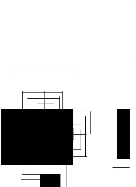
2" Outline drawing for 495, 495G, K4100 diesel engine (Fig. 2) |
|
|
|
3 |
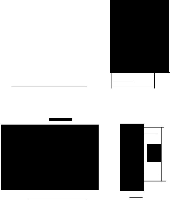
3" Outline drawing for 495T diesel engine (Fig. 3) |
|
|
|
4 |
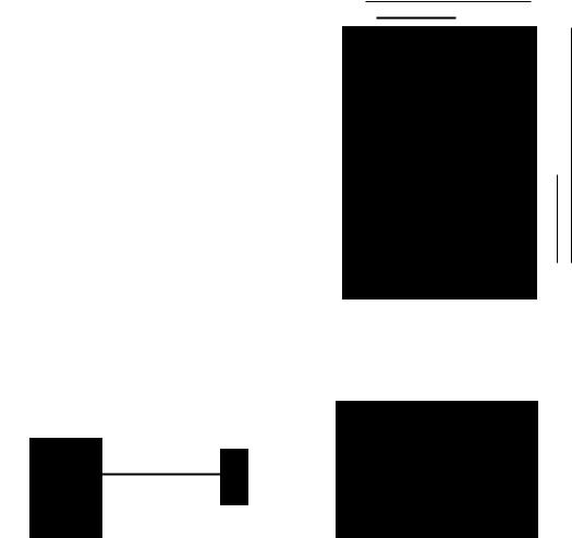
4 ,,·Outline drawing for 495Gl, 495G9, K4100Gl diesel engine (Fig. |
4) |
|
5 |
|
5" Outline drawing for 495G3 diesel engine (Fig. 5) |
|
|
|
6 |
6" Outline drawing for 495GI0, 495G14 diesel engine (Fig. 6) |
|
|
|
7 |
7 "Outline drawing for 495Gll diesel engine (Fig. 7) |
|
|
|
8 |
8" Outline drawing for 4950 diesel engine (Fig. 8) |
|
|
|
9 |
9"Outline drawing for 49501, 495Yl -1, 495G6 diesel engine (Fig. |
9) •........... |
|
10 |
|
10"Outline drawing for 495Y-l, 495Y4 diesel engine (Fig. 10) |
···············.... ·11 |
|||
11"Outline drawing for 495D, 495Dl, 495D2, K4100D diesel engine (Fig. |
11) |
. |
||
....................................................................................................... |
|
|
|
12 |
12"Outline drawing for 495ZD -1, 495ZDl -1, 495ZD2, 495ZD3 diesel engine ~ Fig.
12) |
|
13 |
13"Outline drawing of 495P diesel engine (Fig. |
13) |
14 |
14"Load characteristic curve for 1500,1800, 2000r/min diesel engine (Fig. |
14) ... |
|
....................- |
~ |
15 |
15 "Load characteristic curve for 1500, 1800r/ min turbocharged diesel engine (Fig. 15) 16
16"Speed adjusted characteristic curve for 1600, 2000r/min diesel engine used for
tractors (Fig. 16) |
17 |
17 "Speed and speed adjusted characteristic curve for 2000, 2400r/min diesel engine
used for engineering machines (Fig. 17) |
|
18 |
18" Speed and speed adjusted characteristic curve |
for 2400r/min |
Model ZH4100 |
diesel engine used for engineering machines (Fig. |
18) |
19 |
19"Total output test curve for 2000, 2800r/min diesel engine used for vehicles (Fig. 19) 20
CHAPTER I. Main Technical specification and data for the
diesel engine |
21 |
1.Main technical specification
2.Range for various temperatu~e and pressure
3.Tightening torque of main bolts
4.. Main adjusting data
5.Matchedclearances and wear limit of 495 main parts
6.Matched clearances and wear limit of K4100, ZH4100 main parts
7.Ma.in adjusting. data ofZH4100 diesel engine
CHAPTER II. Main structure and replacing and repairing
method of diesel engine |
31 |
1.Cylinder block assembly
2.cylinder block and, related assembly
3.Piston and connecting rod asse-mbty
4.Crankshaft and flywheel assembly
5.Intake and exhaust system and turbocharger
6.Fuel system
7.Lubricating system
8.Cooling system
9.'Electricsystem
10. Transmission system
11. Power take out equipment
12. The main changed parts of K4100 diesel engine
13. The main changed parts of ZH4100 diesel engine
CHAPTER III. Operation of diesel engine |
44 |
|
1. |
Transportation and installation |
|
2. |
Fuel, oil and cooling water |
|
3. |
Preparati.on before starting |
|
4. |
Starting |
|
5. |
Running |
|
;6., Stopping
7. Safe and technical operation rule
CHAPTER N. Technical maintenance of diesel engine |
49 |
|
1. |
Working day maintenance |
|
2. |
First grade .technique mainenance |
|
3. |
Second grade technique maintenance |
|
4. |
Third grade technique maintenance |
|
5. |
Technique mauntenance on winter working |
|
CHAPTER V. TroublE.? and remedy method |
51 |
1.Start failures
2.Unsteady running
3.Output is instfficient of drops suddenly
4.Abnormal noise during engine iperation
5.Abnormal exhaust smoke
6.Insufficient oil pressure
7.Oil temperature too high.
8.The temperature of used cooling water too high
9.Trouble in the injection pump
10.Insufficient fuel supply of the fuel delivery pump
11.Injector in trouble
12.Governor in trouble
13.Engine stops suddenly
14.Charged dynamo out of order
15.Starting motor be in trouble
16.Governor in trouble
17.Turbocharger in trouble
18.Air compressor in trouble
19.Clutch in trouble
APPENDIX: The wearing in of the diesel engine |
64" |
Fig. la Longitudinal sectional drawing for 495 diesel engine
• 1 •
Fig. 1b Cross sectional drawing for 495 diesel engine
· 2 ·
40° _ - .. -_____
10° |
10° |
|
27°
27°
445
Fig.2 Outline drawing for 495, 495G,
o
00
00
694
- |
|
|
|
|
|
|
|
|
~a |
|
|
|
|
|
|
|
|
~ |
|
|
|
|
|
|
|
|
[' |
|
|
|
|
|
|
|
|
z |
|
|
|
|
|
|
|
|
[' |
|
|
|
|
|
|
|
|
•~ |
|
|
|
~Q |
{: |
|
|
|
|
|
|
|
|
Cit |
~ |
|
|
|
|
|
|
|
:c |
:c |
|
|
|
|
|
|
|
~ |
\0 |
|
|
|
|
|
|
|
•N |
•;; |
|
|
|
|
|
|
|
|
|
|
|
-+10-184.--5 ± 0.5
K4100 diesel engine
• 3 •
N
N
N
0
~
893
212 |
182 |
158 152
60 90
N
~ S ~ N
~
00
~
0
N
N
320
420
~~ |
|
|
|
|
|
|
|
99 |
|
|
|
I" |
|
|
|
Z |
|
|
|
l"'- |
|
|
|
"l:t |
|
|
~o |
|
|
||
• |
|
|
t- |
|
|
|
oo |
|
|
|
:x: |
|
|
|
|
|
|
|
-...0 |
|
|
||
|
|
|
0'\ |
|
|
|
•N |
|
|
|
|
|
|
|
|
|
|
|
|
|
|
|
|
36
30 79
Fig.3 Outline drawing for 495T diesel engine

|
|
|
|
8-M12 |
|
|||
|
605 |
50 |
20 |
316 |
|
|||
|
|
|||||||
|
825 |
|
|
|
|
|
|
|
|
|
|
268 |
|
|
|||
|
|
|
|
|
||||
|
|
|
|
|
|
|
|
|
|
|
|
|
|
|
|
|
|
9-MJ2
Thread depth 19
12-MIOeven distributed
Thread depth 20
22.5°
445 |
90 |
|
|
|
|
Fig.4 Outline drawing for 495Gl , 495G9, |
K4100Gl |
diesel engine |
* The air cleaner, exhaust manifold & oil gauge of 495G9 |
||
are the same as those of 495 |
(see Fig. |
2) |
· 5 ·

242 189
o
~
00
615
844
212
158 |
|
182 |
|
|
|
|
|
|
|
|
|
|
|
|
|
|
|
||
60 |
90 |
|
30 |
|
79 |
|
|
||
|
|
|
|||||||
|
|
|
|
|
|
|
|
|
|
|
|
|
|
|
|
|
|
|
|
N |
|
|
|
|
|
|
N |
|
N |
|
|
|
|
|
|
N |
|
N |
0 |
|
|
|
|
|||
|
|
|
|
|
||||
|
|
~ |
|
|
|
|
|
|
|
|
|
|
|
0 |
|
|
|
|
|
|
|
|
'I") |
|
|
|
|
|
|
|
|
|
|
|
|
|
|
|
|
|
~ |
|
|
|
|
|
12-.12.5 |
|
|
|
|
||
Il-M12 even distributed
Thread depth 25
4 |
r |
36 |
|
|
|
||
|
|
|
|
436( ± 0.03)
218 ± 0.03
466 ± 0.05
Fig.5 Outline drawing for 495G3 diesel engine
8-M12
|
|
Thread |
depth |
||
|
|
|
|
|
316 |
605 |
50 |
20 |
|
268 |
|
874
9-M12
Thread depth 19
± 0.5
22.5 0 |
22.5 0 |
90
445
Fig.6 Outline drawing for 495GIO, 495G14 diesel engine
* The length dimension of 495G14
is the same as 495Gl (see Fig. 4)
• 7 •

836 |
32 |
253 |
|
969
The connecting dimension of |
The connecting dimension of |
the diesel engine |
the clutch shell |
228
4-M14
836 |
|
114 |
120 |
Fig.7 Outline drawing for 495Gll diesel engine
· 8 ·

318
694
6-M8 |
6 |
|
Thread depth |
16 |
|
9-MJ2
(
00
:c
~
•":t
90 |
+: 0.5 |
445
Fig.8 Outline drawing for 4950 diesel engine
· 9·
675
4
|
848 |
32 |
|
949 |
|
The installing dimension of |
The connecting dimension of |
~he diesel engine |
the clutch shell |
846 |
2- 13 |
Fig.9 Outline drawing for 49501 , 495Yl - 1, 495G6 diesel engine
*The exhaust manifold height 107 of 495Yl - 1 is 255
** The inlet & exhaust manifold and air cleaner of 495G6
are the same as 495G2
• 10 •

The installing dimension of |
The |
connecting dimension of |
the diesel engine |
the |
clutch shell |
|
|
|
|
|
|
|
|
|
|
|
|
|
|
|
|
|
|
|
|
|
|
|
|
|
786 |
|
|
|
32 |
|
|
|
|
|
|
|
|
|
|
|
|||
|
|
|
|
|
|
|
|
|
|
|
Fig. 10 Outline drawing for 495Y -1 , 495Y4 diesel engine
· 11 ·

318
694
even
6-4>36~iIIIdistributed
Both sides
22.5° 22.5°
445
Note: The dimension in the brackets is the length of 41000
Fig.ll Outline drawing for 4950,49501,49502, K41000 diesel engine
• 12 •
686
9-\1'2
even
6-.36~(;il(,distributed
Both sides
27':
445
V)
00
N
§o
":f
..................1 -- ~ ~
• Q5
•~
6
Fig. 12 Outline drawing for 495ZD -1 , 495ZDl -1 ,
495ZD2, 495ZD3 diesel engine
· 13 •

OPlt
O£:6
00
rr.
Fig. 13 Outline drawing of 495P diesel engine
· 14 ·
 Loading...