

Weboost Connect RV65 User Manual

A WILSON ELECTRONICS BRAND
CONNECT RV 65
RV Cellular Signal Booster
With Telescoping Pole
User Manual

______
Index
Package Contents
STEP 1: Mount Outside Antenna
STEP 2: Mount Telescoping Pole To RV
STEP 3: Booster Location
STEP 4: Mount Inside Antenna
STEP 5: Connect Power Supply
Test System: Lights
Safety Guidelines
Specifi cations
Warranty
1
2
3
5
7
9
10
12
14
15
________
Package
Contents
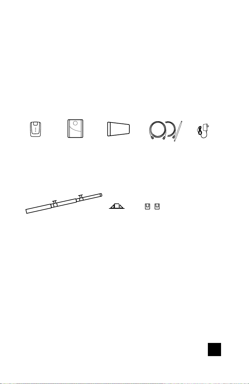
Contents of Box 1
Booster
Inside
Antenna
Contents of Box 2
Telescoping
Pole
Outside
Antenna
Ground
Mount
Coax Cables
2 - 15ft. 1 - 30ft.
+ Flat Cable
Wall
Mounts
Power
Supply
CONNECT RV 65 RV CELLULAR SIGNAL BOOSTER
1

______
Step 1: Mount Outside
Antenna To Telescoping Pole
Mount outside antenna to telescoping pole (using the included
hardware). See examples below.
Run the coax cable through
L-Bracket and mount using the
phillips screws and lock washers.
NOTE: Do not over tighten.
Drip hole
Connect coax cable to outside antenna after mounting to
telescoping pole.
2
RV CELLULAR SIGNAL BOOSTER CONNECT RV 65
______
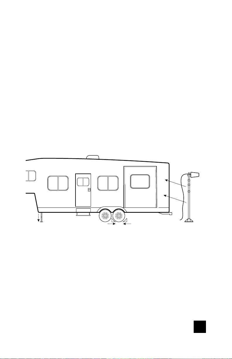
Step 2: Mount Telescoping
Pole To Side Of RV
Determine where you want to mount telescoping pole on your
RV. Extend pole to maximum height. Use wall mount plates
and ground mount to secure pole. We recommend mounting
near slider or toy hauler ramp door on the side.
NOTE: DO NOT INSTALL POLE ON RV UNTIL STABILIZER JACKS AND
WHEELS CHOCKS ARE IN PLACE AND RV IS IMMOBILIZED.
Recommended
placement
Stabilizer
jacks down
WARNING: Check for and avoid any powerlines or overhead obstructions
there may be.
CONNECT RV 65 RV CELLULAR SIGNAL BOOSTER
Wheel chocks in
place
3
______
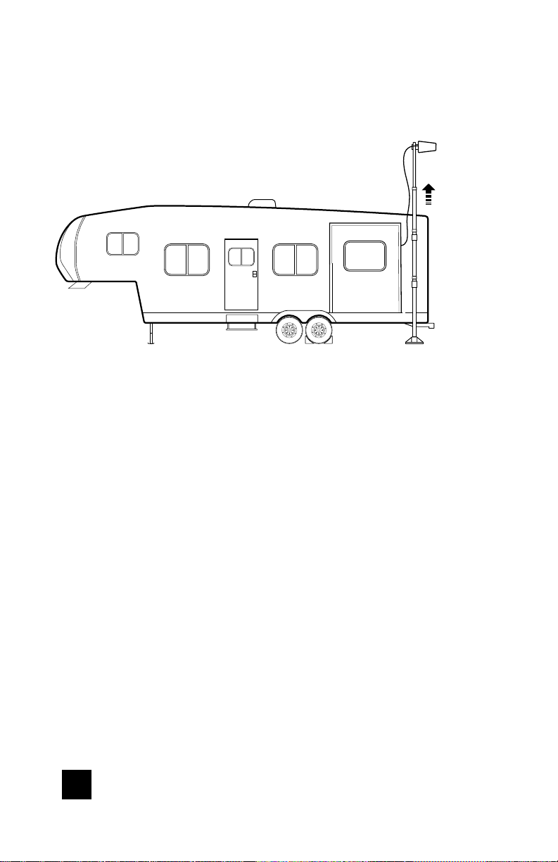
(STEP 2 Mounting Telescoping Pole cont.)
Outside Antenna
Extend
Pole
Min. 4 ft.
separation
between wall
plates
(stakes can be used to secure to ground, not included)
Ground Mount
Clean the fl at surface of the RV where wall mounts will be
placed. Fully extend the pole and attach the wall mount to
the top black ‘foot’ mount located on the pole. Remove the
adhesive backer and, making sure the pole is level at a 90°
angle, fi rmly attach the wall mount to the RV near the top.
There must be at least 4’ of separation between the top and
bottom mounts for best performance. Next, attach the other
wall mount to the bottom foot mount located on the pole and
insert the attached pin. Then remove the adhesive backer and
stick to the clean, fl at surface.
RVs With Corrugated Sides
We recommend using the side of a slider. Just ensure the following:
• There is enough clearance for the wall mount to
be retracted into the slider.
• There is still 4’ of separation.
4
RV CELLULAR SIGNAL BOOSTER CONNECT RV 65
 Loading...