

Page 1
A WILSON ELECTRONICS BRAND
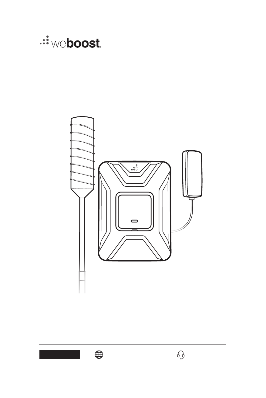
DRIVE X OTR FLEET
Cell Signal Booster For Fleet Trucks
Installation Guide
NEED HELP?
GDE000262_DriveX_OTR_Fleet_Rev01_02-20-20.indd 1GDE000262_DriveX_OTR_Fleet_Rev01_02-20-20.indd 1 2/20/2020 4:01:26 PM2/20/2020 4:01:26 PM
support.weboost.com 866.294.1660
Page 2
______
Index
Package Contents
STEP 1: Select Mounting Location
STEP 2: Assemble The Antenna
STEP 3: Mount Outside Antenna
STEP 4: Mount Inside Antenna
STEP 5: Wiring The Power Supply To Vehicle Battery
STEP 6: Connect Coax Cables To Booster
STEP 7: Connect Power Supply To Booster
Light Patterns
Troubleshooting
1
2
3
5
7
8
9
10
11
12
Safety Guidelines
Specifications
Warranty
GDE000262_DriveX_OTR_Fleet_Rev01_02-20-20.indd 2GDE000262_DriveX_OTR_Fleet_Rev01_02-20-20.indd 2 2/20/2020 4:01:26 PM2/20/2020 4:01:26 PM
13
14
15
Page 3
DRIVE X OTR FLEET CELL SIGNAL BOOSTER
________
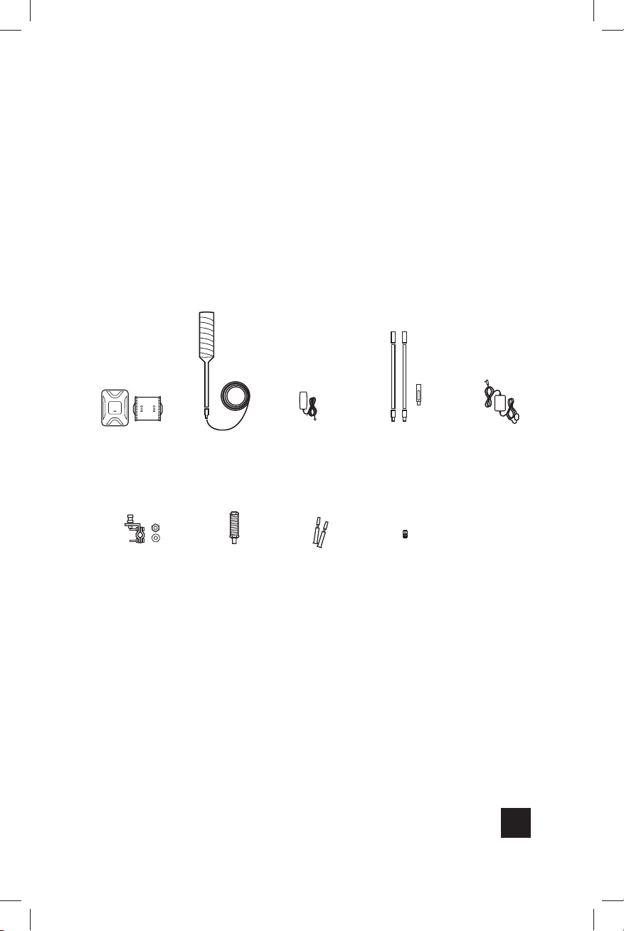
Package
Contents
Booster
& Bracket
3- Way Antenna
Mount
Outside
Antenna
Antenna
Spring
Inside
Antenna
Thread
Lock
Mast Extensions
& Side Exit Adapter
Cable
Adapter
Power
Supply
1
GDE000262_DriveX_OTR_Fleet_Rev01_02-20-20.indd 1GDE000262_DriveX_OTR_Fleet_Rev01_02-20-20.indd 1 2/20/2020 4:01:26 PM2/20/2020 4:01:26 PM
Page 4
CELL SIGNAL BOOSTER DRIVE X OTR FLEET
______
Step 1: Select Mounting
Location
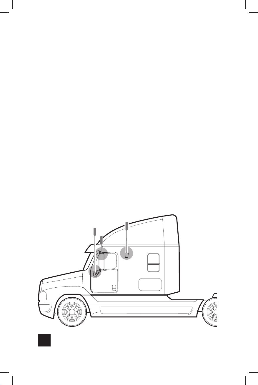
Select mounting location on vehicle. The antenna can be
mounted in any CB mount or antenna mounting point on the
vehicle. For best performance mount the antenna above the
metal cab (it does not need to be above cab wind deflector).
Depending on the type of truck, there may be built-in antenna
mounting points. If the vehicle does not have built-in mounting
points, the antenna includes a three-way mount that will work
on vehicles with mirror rails. The antenna will also work with
third party CB antenna mounts.
NOTE: Mount at least 12 inches from any other antennas. Free of obstructions.
NOTE: If the vehicle is using two CB antennas co-phase wiring, removing one
antenna will cause reduced performance of the remaining CB antenna.
Typical Antenna
Mounting Points
2
GDE000262_DriveX_OTR_Fleet_Rev01_02-20-20.indd 2GDE000262_DriveX_OTR_Fleet_Rev01_02-20-20.indd 2 2/20/2020 4:01:26 PM2/20/2020 4:01:26 PM
Page 5
DRIVE X OTR FLEET CELL SIGNAL BOOSTER
______
Step 2: Assemble The
Antenna
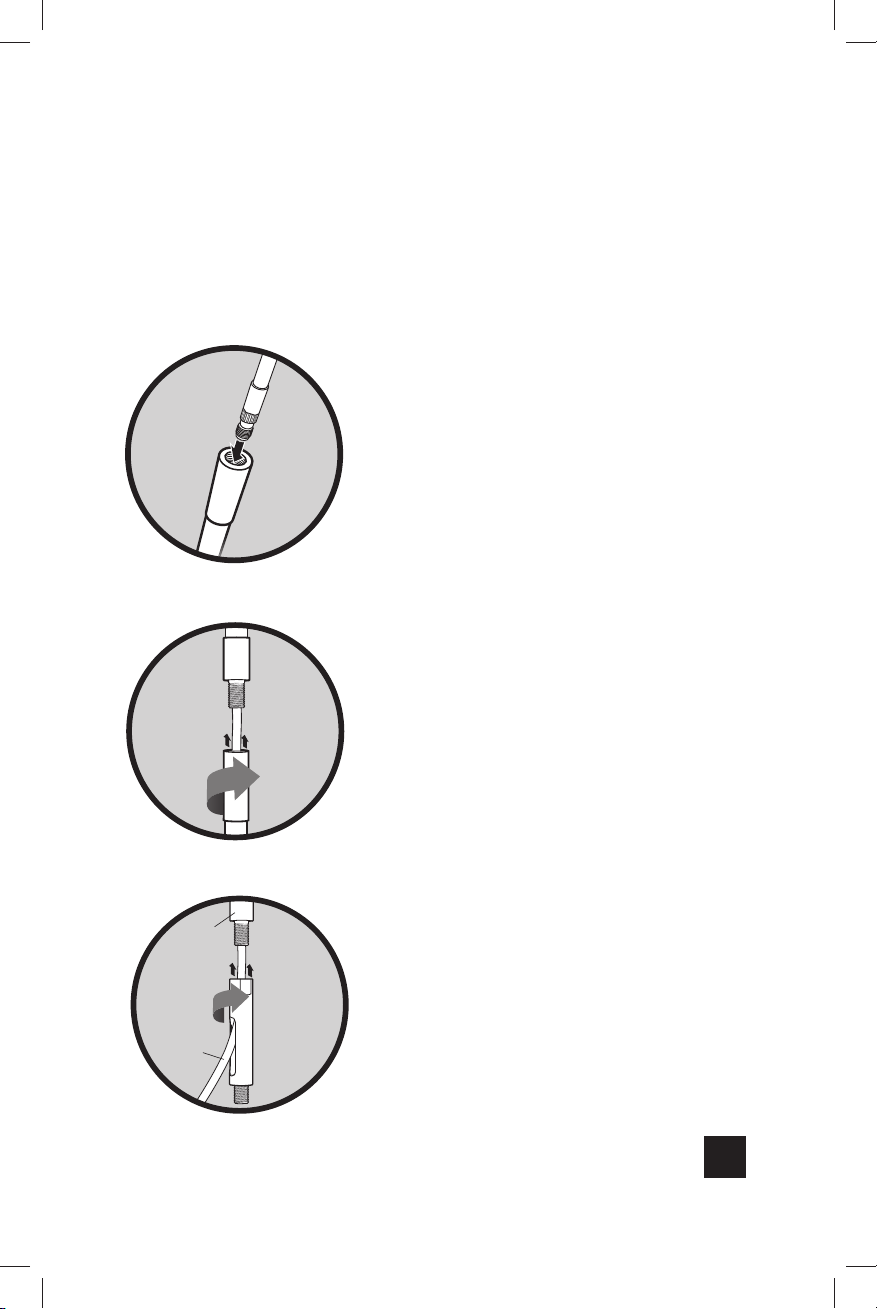
Once you have determined the
cable
from antenna
Mast
Extension
best location for the antenna
and have determined if Mast
Extensions are needed, insert
cable through mast.
NOTE: Mast Extensions may not be
needed depending on your mounting
point.
OTR
Antenna
If using Mast Extension(s) add
thread locker (provided) to thread
point(s). Screw into place.
Mast
Extension
Mast
Extension
OR
Antenna
Side Exit
cable
Adapter
NOTE: Be sure the antenna is the correct
height before applying thread locker.
Add thread locker (provided) to
thread point and screw on the
Side Exit Adapter.
NOTE: When adding the side exit adapter
hold the antenna vertically and screw the
adapter from the bottom up. This reduces
cable twisting.
3
GDE000262_DriveX_OTR_Fleet_Rev01_02-20-20.indd 3GDE000262_DriveX_OTR_Fleet_Rev01_02-20-20.indd 3 2/20/2020 4:01:27 PM2/20/2020 4:01:27 PM
Page 6
CELL SIGNAL BOOSTER DRIVE X OTR FLEET
______
(STEP 2 cont.)
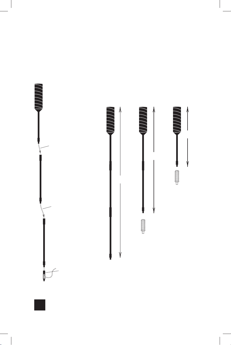
OTR
Antenna
run cable through
Mast Extension
Mast
Extension
run cable through
Mast Extension
NOTE: The included spring should
only be used on shorter masts
variations.
32”
45”
Antenna Spring
(can be used
optionally)
17”
Mast
Extension
Side
Exit Adapter
(Antenna Spring
should not be used
on this length)
Antenna Spring
(can be used
optionally)
4
GDE000262_DriveX_OTR_Fleet_Rev01_02-20-20.indd 4GDE000262_DriveX_OTR_Fleet_Rev01_02-20-20.indd 4 2/20/2020 4:01:27 PM2/20/2020 4:01:27 PM
Page 7
DRIVE X OTR FLEET CELL SIGNAL BOOSTER
______
Step 3: Mount Outside
Antenna
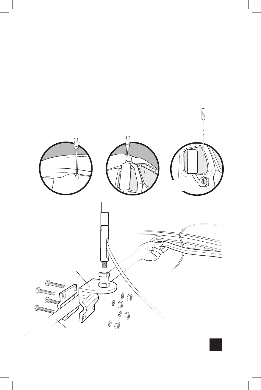
These are some typical antenna mounting points. If the vehicle
does not have built-in mounting points, a three-way mount is
included that will work on vehicles with mirror rails.
Top of mirror Mirror ArmUpper Side
3-Way Mount
on bird perch
mast
side exit
adapter
Antenna Mount
3-Way
mirror rail
or bird perch mount
The cable is strong enough
that it may be shut in most
vehicle doors without
damaging the cable.
5
GDE000262_DriveX_OTR_Fleet_Rev01_02-20-20.indd 5GDE000262_DriveX_OTR_Fleet_Rev01_02-20-20.indd 5 2/20/2020 4:01:28 PM2/20/2020 4:01:28 PM
Page 8
CELL SIGNAL BOOSTER DRIVE X OTR FLEET
______
(STEP 3 cont.)
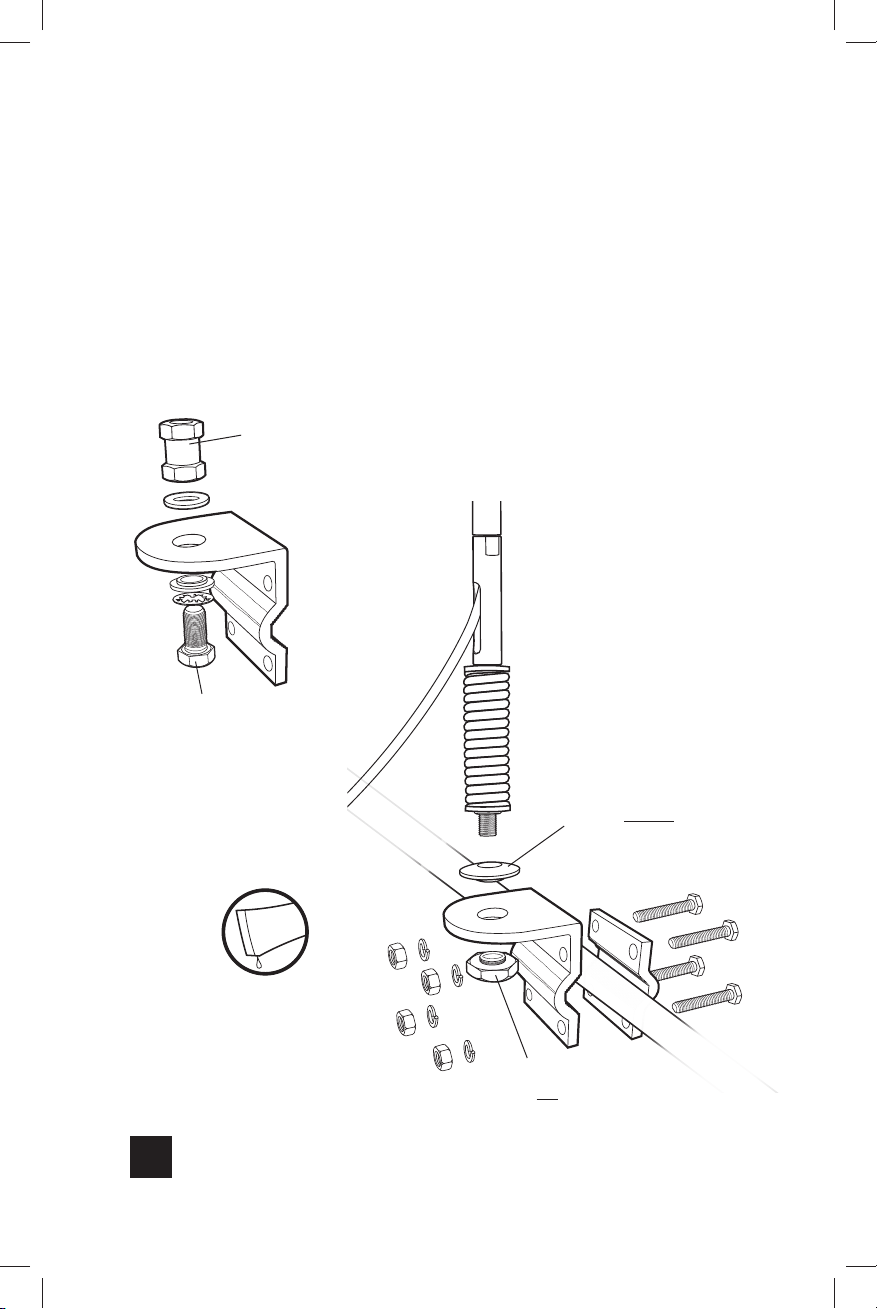
If installing with the Spring, disassemble and reassemble the
3-Way Mount as shown below.
Disassemble
Remove nut &
shakeproof washer
Remove bolt &
plastic washer
Resassemble
Side Exit
Adapter
Side Exit Adapter must
be used with Spring
Spring
Mount disc washer with
lip in the DOWN position
Add thread lock on
all threads with tube
provided
Fasten nut with lip in
the UP position
6
GDE000262_DriveX_OTR_Fleet_Rev01_02-20-20.indd 6GDE000262_DriveX_OTR_Fleet_Rev01_02-20-20.indd 6 2/20/2020 4:01:28 PM2/20/2020 4:01:28 PM
Page 9
DRIVE X OTR FLEET CELL SIGNAL BOOSTER
______
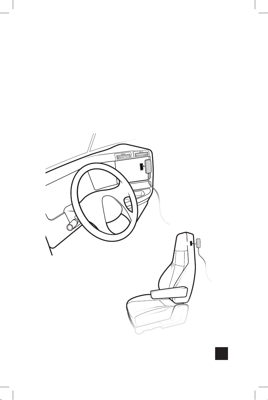
Step 4: Mount Inside Antenna
Identify a place to mount the In-Vehicle Antenna, either on the
side of the seat or on the dash and mount. The location should
be at least 18 inches but no more than 36 inches from where
the cellular device will be used. Use the Velcro® adhesive
strip/adhesive strip provided and attach to desired location.
Velcro®
In-Vehicle
Antenna
Velcro®
In-Vehicle
Antenna
GDE000262_DriveX_OTR_Fleet_Rev01_02-20-20.indd 7GDE000262_DriveX_OTR_Fleet_Rev01_02-20-20.indd 7 2/20/2020 4:01:29 PM2/20/2020 4:01:29 PM
7
Page 10

CELL SIGNAL BOOSTER DRIVE X OTR FLEET
______
Step 5: Wiring The Power
Supply To Vehicle Battery
Use steps below as a draft/template of the general install of
the power supply.
Before connecting the power supply, disconnect the vehicle battery
1
leads to avoid any electrical shocks during installation.
Locate a place where cables are already running through the firewall
2
(rear wall of engine bay) to the inside of the cabin.
Locate the same firewall hole from inside of the vehicle cabin.
3
Route the power cables of the power supply from the inside of the
4
vehicle cabin out through firewall hole.
Note: The cables must be routed inside to outside since the power
supply brick won’t fit through the firewall holes. The power supply
brick should remain inside the vehicle cabin.
Connect the positive lead of the power supply (lead with red tape)
5
to the disconnected positive (+) lead of the battery (not the positive
terminal on the battery itself).
Connect the negative lead of the power supply (lead without tape)
6
to the disconnected negative (-) lead of the battery (not the negative
terminal on the battery itself).
Connect the positive (+) lead back to the vehicle battery.
7
Connect the negative (-) lead back to the vehicle battery.
8
NOTE: Having the power supply directly connected to the battery may
drain the battery’s life. Please review the vehicle’s owner’s manual for more
information. Adding a “fuse tap” may be another solution. A “fuse tap” is an
electrical part that functions as a power splitter and is meant to be installed
in the car’s fuse box, making the amp shut o when the vehicle’s ignition
switch is turned o.
IMPORTANT: Power supply must be wired to fuse.
8
GDE000262_DriveX_OTR_Fleet_Rev01_02-20-20.indd 8GDE000262_DriveX_OTR_Fleet_Rev01_02-20-20.indd 8 2/20/2020 4:01:29 PM2/20/2020 4:01:29 PM
Page 11
DRIVE X OTR FLEET CELL SIGNAL BOOSTER
______
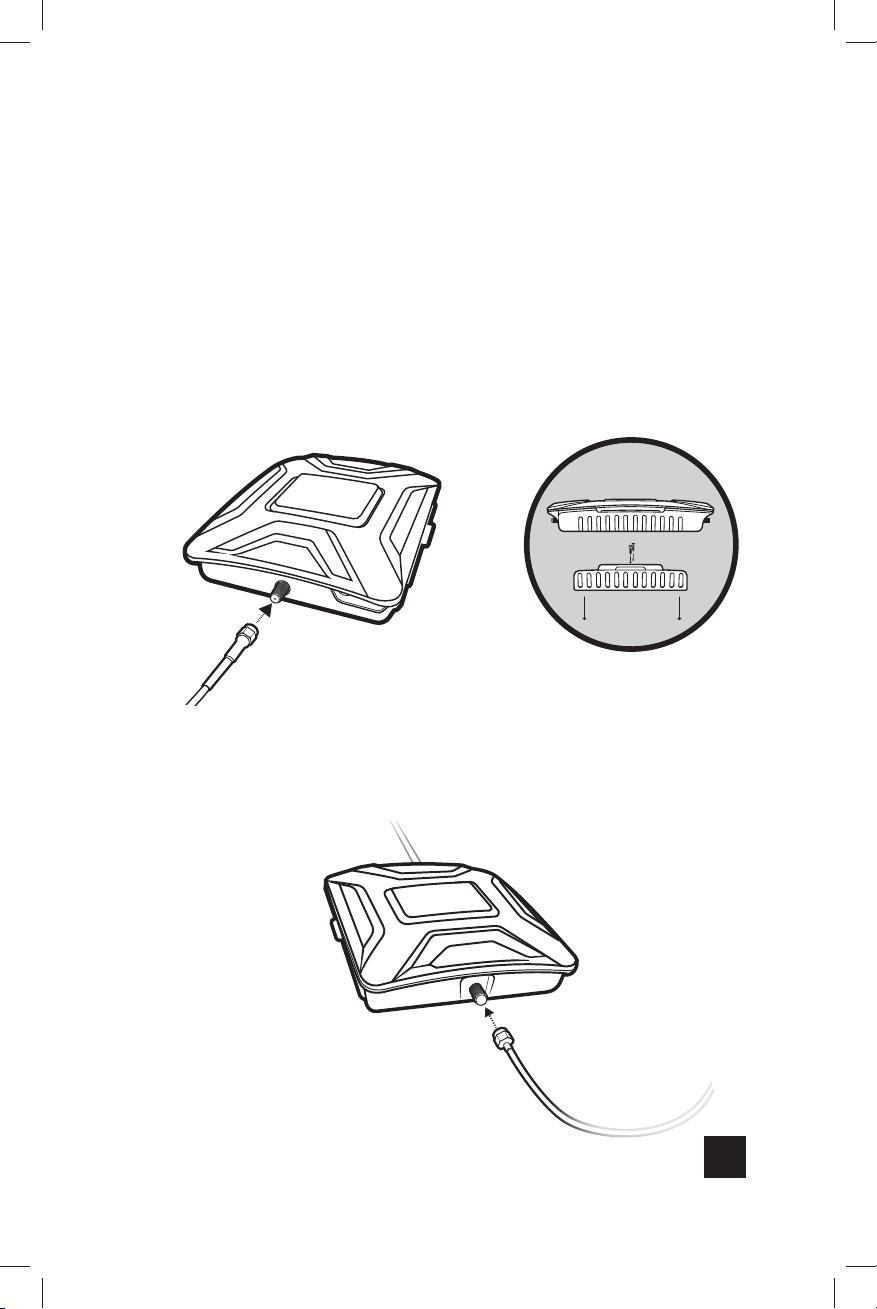
Step 6: Connect Coax Cables
To Booster
Connect the cable from the Outside Antenna to the port
labeled “Outside Antenna” on the Drive X booster.
NOTE: Bracket can be used to fasten booster in a specific location if desired.
from Outside Antenna
Connect the cable from the In-Vehicle Antenna to the port
labeled “Inside Antenna” on the booster.
from Inside Antenna
9
GDE000262_DriveX_OTR_Fleet_Rev01_02-20-20.indd 9GDE000262_DriveX_OTR_Fleet_Rev01_02-20-20.indd 9 2/20/2020 4:01:29 PM2/20/2020 4:01:29 PM
Page 12
CELL SIGNAL BOOSTER DRIVE X OTR FLEET
______
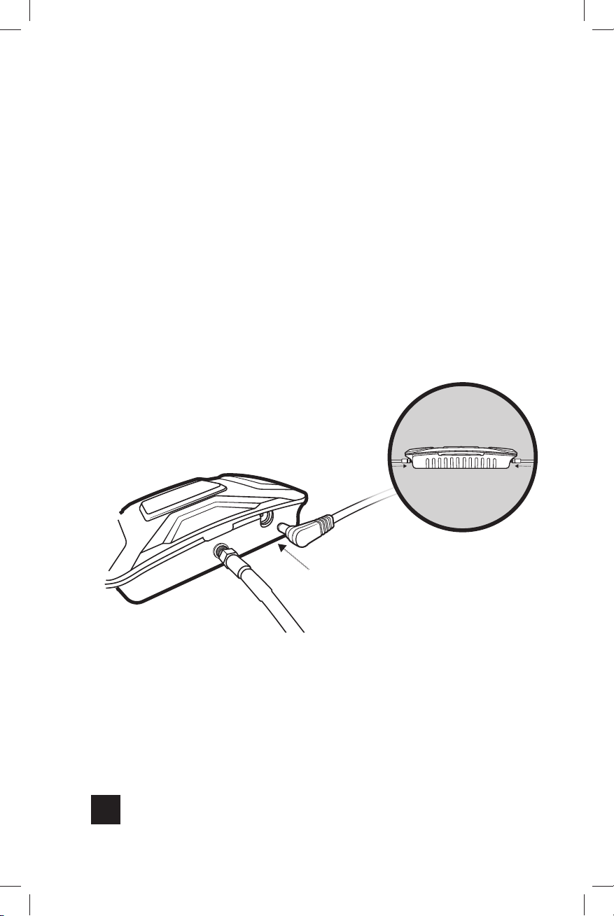
Step 7: Connect Power
Supply To Booster
Connect the power supply cord to the end of the Drive X
labeled “Power.”
NOTE: Do NOT connect the power to the Signal Booster until you have
connected both cables from the Inside and Outside Antennas.
Power Supply
10
GDE000262_DriveX_OTR_Fleet_Rev01_02-20-20.indd 10GDE000262_DriveX_OTR_Fleet_Rev01_02-20-20.indd 10 2/20/2020 4:01:30 PM2/20/2020 4:01:30 PM
Page 13
DRIVE X OTR FLEET CELL SIGNAL BOOSTER
______
Light Patterns
Solid Green
This indicates that your booster is functioning properly and there are no issues with
installation.
Blinking Red, Then Solid Green
This indicates that one or more of the booster bands has reduced power due
to a feedback loop condition called oscillation. This is a built in safety feature
to prevent harmful interference with a nearby cell tower. If you are already
experiencing the desired signal boost, then no further adjustments are necessary.
If you are not experiencing the desired boost in coverage then refer to the
Troubleshooting section below.
Solid Red
This is due to a feedback loop condition called oscillation. This is a built in safety
feature that causes a band to shut off to prevent harmful interference with a nearby
cell tower. Refer to Troubleshooting section below.
Light O
If the Drive X Signal Booster’s light is off, verify your power supply has power.
NOTE: The Signal Booster can be reset by disconnecting and reconnecting
the power supply.
After troubleshooting you must initiate a new power cycle by disconnecting and
then reconnecting power to the Booster.
NEED HELP?
GDE000262_DriveX_OTR_Fleet_Rev01_02-20-20.indd 11GDE000262_DriveX_OTR_Fleet_Rev01_02-20-20.indd 11 2/20/2020 4:01:30 PM2/20/2020 4:01:30 PM
support.weboost.com 866.294.1660
11
Page 14

CELL SIGNAL BOOSTER DRIVE X OTR FLEET
______
Troubleshooting
FIXING BLINKING OR SOLID RED ISSUES
This section is only applicable if the booster is red or blinking red and you are not
experiencing the desired signal boost.
Unplug the Booster’s power supply.
1
Relocate the inside and outside antenna further from each other. The objective
2
is to increase the separation distance between them, so that they will not
create this feedback condition discussed before.
Plug power supply back in.
3
Monitor the indicator light on your booster. If, after a few seconds of ‘power
4
on’, a solid or blinking red light appears, repeat steps 1 through 3. Increase the
separation distance until the condition is corrected and/or desired coverage
area is achieved. Note: Horizontal separation of the two antennas typically
requires a shorter separation distance than perpendicular separation.
If you are having any diculties while testing or installing your booster, contact
5
our weBoost Customer Support team for assistance (866.294.1660).
FREQUENTLY ASKED QUESTIONS
What hours can I contact customer support?
Customer Support can be reached monday thru friday by calling 866.294.1660, or
through our support site at support.weboost.com.
Why do I need to create distance between the booster and the antenna?
Antennas connected to a booster create spheres of signal. When these spheres
overlap, a condition called oscillation occurs. Oscillation can be thought of as noise,
which causes the booster to scale down it’s power or shut down to prevent damage.
The best way to keep these spheres of signal from overlapping is to maximize
separation between the inside and outside antennas.
12
GDE000262_DriveX_OTR_Fleet_Rev01_02-20-20.indd 12GDE000262_DriveX_OTR_Fleet_Rev01_02-20-20.indd 12 2/20/2020 4:01:30 PM2/20/2020 4:01:30 PM
Page 15

DRIVE X OTR FLEET CELL SIGNAL BOOSTER
______
Safety Guidelines
Use only the power supply provided in this package. Use of a non-weBoost product may damage
your equipment.
All inside panel and dome antennas must have at least 6’ of separation distance from all active users,
and low profile antennas must have at least 1.5’ separation distance from all active users.
Connecting the Signal Booster directly to the cell phone with use of an adapter will damage the
cell phone.
RF Safety Warning: Any antenna used with this device must be located at least 8 inches from
all persons.
This is a CONSUMER device.
BEFORE USE, you MUST REGISTER THIS DEVICE with your wireless provider and have your
provider’s consent. Most wireless providers consent to the use of signal boosters. Some providers
may not consent to the use of this device on their network. If you are unsure, contact your provider.
You MUST operate this device with approved antennas and cables as specified by the
manufacturer
You MUST cease operating this device immediately if requested by the FCC or licensed wireless
service provider.
WARNING. E911 location information may not be provided or may be inaccurate for calls served by
using this device.
FOR MORE INFORMATION ON REGISTERING YOUR SIGNAL BOOSTER WITH YOUR
WIRELESS PROVIDER, PLEASE SEE BELOW:
Sprint: http://www.sprint.com/legal/fcc_boosters.html
T-Mobile/MetroPCS: https://support.t-mobile.com/docs/DOC-9827
Verizon Wireless: http://www.verizonwireless.com/wcms/consumer/register-signal-booster.html
AT&T: https://securec45.securewebsession.com/attsignalbooster.com/
U.S. Cellular: http://www.uscellular.com/uscellular/support/fcc-booster-registration.jsp
. Antennas MUST be installed at least 20 cm (8 inches) from any person.
13
GDE000262_DriveX_OTR_Fleet_Rev01_02-20-20.indd 13GDE000262_DriveX_OTR_Fleet_Rev01_02-20-20.indd 13 2/20/2020 4:01:30 PM2/20/2020 4:01:30 PM
Page 16
CELL SIGNAL BOOSTER DRIVE X OTR FLEET
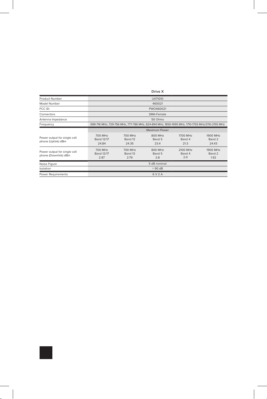
Drive X
Product Number U471010
Model Number 460021
FCC ID: PWO460021
Connectors SMA-Female
Antenna Impedance 50 Ohms
Frequency
699-716 MHz, 729-756 MHz, 777-786 MHz, 824-894 MHz, 1850-1995 MHz, 1710-1755 MHz/2110-2155 MHz
Maximum Power
Power output for single cell
phone (Uplink) dBm
700 MHz
Band 12/17
24.84
700 MHz
Band 13
24.35
800 MHz
Band 5
23.4
1700 MHz
Band 4
21.3
1900 MHz
Band 2
24.43
Power output for single cell
phone (Downlink) dBm
700 MHz
Band 12/17
2.87
700 MHz
Band 13
2.79
800 MHz
Band 5
2.8
2100 MHz
Band 4
2.0
1900 MHz
Band 2
1.92
Noise Figure
5 dB nominal
Isolation > 90 dB
Power Requirements 6 V 2 A
______
Specifications
Each Signal Booster is individually tested and factory set to ensure FCC compliance. The Signal Booster cannot be adjusted without
factory reprogramming or disabling the hardware. The Signal Booster will amplify, but not alter incoming and outgoing signals in order
to increase coverage of authorized frequency bands only. If the Signal Booster is not in use for five minutes, it will reduce gain until a
signal is detected. If a detected signal is too high in a frequency band, or if the Signal Booster detects an oscillation, the Signal Booster
will automatically turn the power o on that band. For a detected oscillation the Signal Booster will automatically resume normal
operation after a minimum of 1 minute. After 5 (five) such automatic restarts, any problematic bands are permanently shut o until the
Signal Booster has been manually restarted by momentarily removing power from the Signal Booster. Noise power, gain, and linearity
are maintained by the Signal Booster’s microprocessor.
This device complies with Part 15 of FCC rules. Operation is subject to two conditions: (1) This device may not cause harmful
interference, and (2) this device must accept any interference received, including interference that may cause undesired operation.
Changes or modifications not expressly approved by weBoost could void the authority to operate this equipment.
14
GDE000262_DriveX_OTR_Fleet_Rev01_02-20-20.indd 14GDE000262_DriveX_OTR_Fleet_Rev01_02-20-20.indd 14 2/20/2020 4:01:30 PM2/20/2020 4:01:30 PM
Page 17
DRIVE X OTR FLEET CELL SIGNAL BOOSTER
2 YEAR WARRANTY
weBoost Signal Boosters are warranted for two (2) years against defects in
workmanship and/or materials. Warranty cases may be resolved by returning the
product directly to the reseller with a dated proof of purchase.
Signal Boosters may also be returned directly to the manufacturer at the
consumer’s expense, with a dated proof of purchase and a Returned Material
Authorization (RMA) number supplied by weoost. weBoost shall, at its option,
either repair or replace the product.
This warranty does not apply to any Signal Boosters determined by weBoost
to have been subjected to misuse, abuse, neglect, or mishandling that alters or
damages physical or electronic properties.
Replacement products may include refurbished weBoost products that have been
recertified to conform with product specifications.
RMA numbers may be obtained by contacting Customer Support
DISCLAIMER: The information provided by weBoost is believed to be complete
and accurate. However, no responsibility is assumed by weBoost for any business
or personal losses arising from its use, or for any infringements of patents or other
rights of third parties that may result from its use.
15
GDE000262_DriveX_OTR_Fleet_Rev01_02-20-20.indd 15GDE000262_DriveX_OTR_Fleet_Rev01_02-20-20.indd 15 2/20/2020 4:01:30 PM2/20/2020 4:01:30 PM
Page 18
CELL SIGNAL BOOSTER DRIVE X OTR FLEET
Notes
NEED HELP?
support.weboost.com 866.294.1660
16
GDE000262_DriveX_OTR_Fleet_Rev01_02-20-20.indd 16GDE000262_DriveX_OTR_Fleet_Rev01_02-20-20.indd 16 2/20/2020 4:01:30 PM2/20/2020 4:01:30 PM
Page 19
DRIVE X OTR FLEET CELL SIGNAL BOOSTER
Notes
NEED HELP?
support.weboost.com 866.294.1660
17
GDE000262_DriveX_OTR_Fleet_Rev01_02-20-20.indd 17GDE000262_DriveX_OTR_Fleet_Rev01_02-20-20.indd 17 2/20/2020 4:01:30 PM2/20/2020 4:01:30 PM
Page 20

3301 East Deseret Drive, St. George, UT
866.294.1660
Copyright © 2020 weBoost. All rights reserved.
weBoost products covered by U.S. patent(s) and pending application(s)
For patents go to: weboost.com/us/patents
www.weboost.com support.weboost.com
NOT AFFILIATED WITH WILSON ANTENNA
GDE000262_DriveX_OTR_Fleet_Rev01_02-20-20.indd 18GDE000262_DriveX_OTR_Fleet_Rev01_02-20-20.indd 18 2/20/2020 4:01:30 PM2/20/2020 4:01:30 PM
GDE000262_Rev01_02.20.20
 Loading...