

Page 1
A
S
f
(
SUMMIT
®
PLATINUM D4 / D6
BUILT-IN NG GAS GRILL INSTALLATION GUIDE
THIS GAS APPLIANCE IS DESIGNED
FOR OUTDOOR USE ONLY.
42370
LOCATING YOUR GRILL
When determining a suitable location for your Summit® gas grill installation, give attention to concerns such as exposure to wind, proximity to traffi c paths, and
keeping any gas supply lines as short as possible. Never locate the Summit® gas grill in a garage, breezeway, shed, under an unprotected overhang, or other
enclosed area. Locate the grill and structure so there is enough room to safely evacuate the area in case of a fi re.
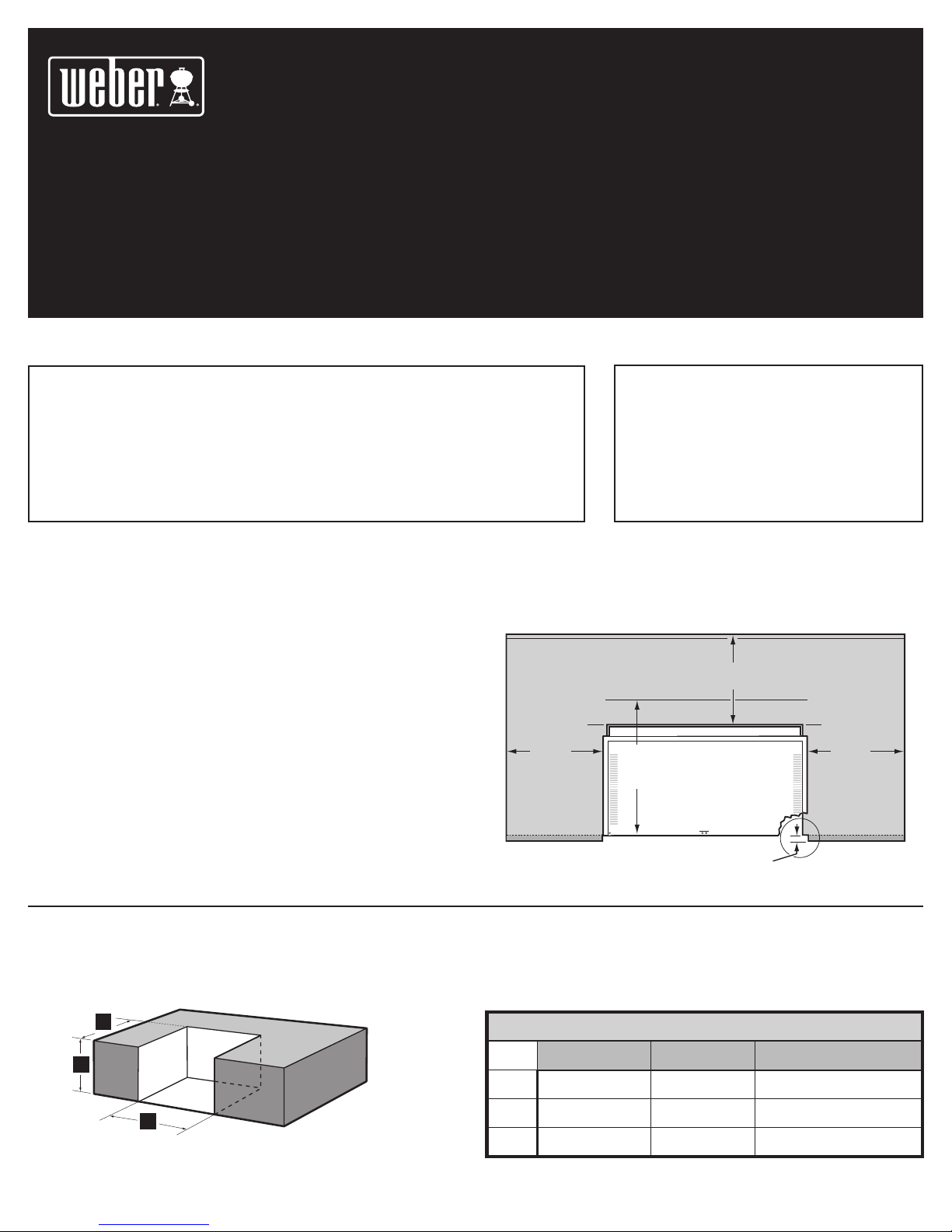
CLEARANCE FROM SURFACES OR STRUCTURES
24 inches (61 cm) Any Surface
WARNING: Clearance from any surface or structure is
24 inches (609.6 mm) from the back and sides of the grill.
Refer to “Typical Gas Supply Installation” before starting
installation.
WARNING: The structure, “island”, countertops, and
adjacent work areas for the built-in grill installation must be
built from noncombustible materials only.
NOTE: If you have questions on what materials are considered noncombustible,
contact your local building materials supplier or fi re department.
BUILT-IN STRUCTURE CUTOUT DIMENSIONS
ALL DIMENSIONS ARE TO FINISHED SURFACES.
Any Surface
24 inches
24 inches
(61 cm)
27 inches (685.8 mm) min. for
lid clearance
Grill Frame
Note: For a countertop treatment: Recommended 3/4 inch
19.1 cm) overhang. Notch front edge for frame to fully
slide in.
(61 cm)
WARNING: All countertop fi nished surfaces must be
constructed of a noncombustible material.
ny
ur
ace
3
2
1
Built-In Cutout Dimensions
1
2
3
D4 D6 Tolerances
1
30
˝ 38
/
4
1
˝ 34
/
34
4
21˝ 21˝ +
1
˝+
/
4
1
˝+
/
4
1
” -
/
4
1
” -
/
4
1
” -
/
4
42370 US 10/01/05
1
˝
/
4
1
˝
/
4
1
˝
/
4
NG
Page 2
2
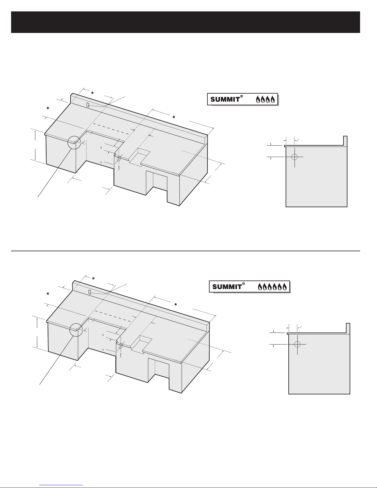
BUILT-IN CUTOUT DIMENSIONS
GENERAL CONSTRUCTION DETAILS
Summit® Built-In unit and all other accessory units should be on site before construction begins. All dimensions have a tolerance of plus or minus (+/-) 1/4
inch.The grill frame rests directly on the Island Structure top fi nished surface. Make sure this surface is level. Do not support the grill from the bottom. If the
supporting structure is going to have an electrical outlet for a rotisserie, it should be on the left side of the structure.
24"
min.
24"
min.
6
3
1
"
/
4
34
30
21"
1
"
/
4
1
"
/
4
Built-In
Frame
Note: For a countertop treatment:
Recommended
Notch front edge for frame to fully slide in.
3
inch overhang.
/
4
Access for electric
on left hand side
4B
24"
min.
3
"
/
4
Gas Inlet
min.
Side Burner
Opening
27 inches min.
1
6
"
/
4
3
3
/
4
Gas Inlet
1/2"
10
distance from front
edge of the cutout
for open lid clearance
*Clearance from any surface or structure is at least 24 inches from the back and
sides of the grill.
"
24"
min.
24"
min.
6
3
1
"
/
4
34
1
"
/
4
21"
38
1
"
/
4
Built-In
Frame
Note: For a countertop treatment:
Recommended
Notch front edge for frame to fully slide in.
3
inch overhang.
/
4
Access for electric
on left hand side
6B
24"
min.
3
"
/
4
Gas Inlet
min.
Side Burner
Opening
27 inches min.
1
6
"
/
4
3
"
/
3
4
Gas Inlet
1/2"
10
distance from front
edge of the cutout
for open lid clearance
*Clearance from any surface or structure is at least 24 inches from the back and
sides of the grill.
Page 3
4B
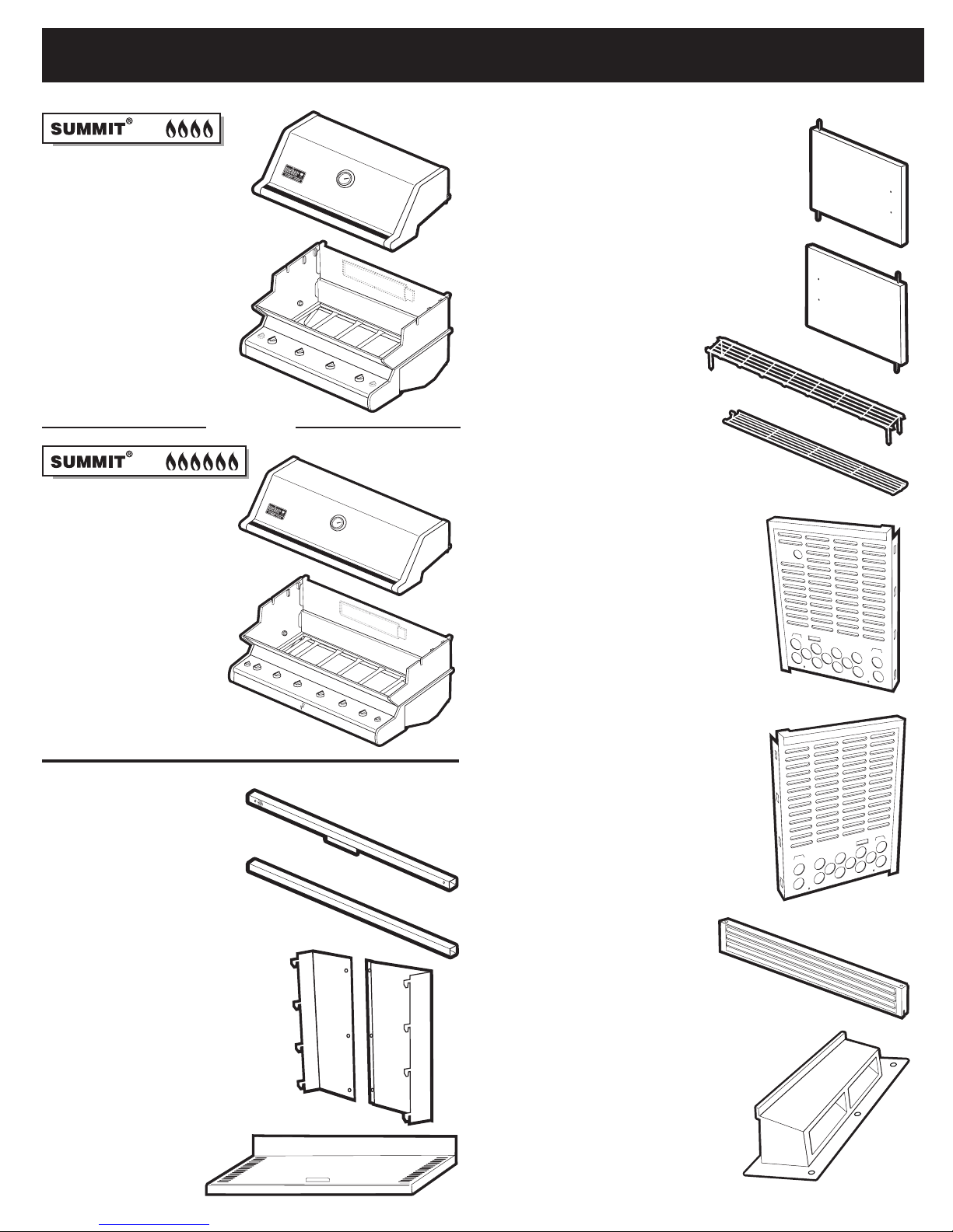
PARTS LIST
3
Lid - 1
Cookbox - 1
Lid - 1
6B
OR
Left Door - 1
Right Door - 1
Warming Rack - 1
Warm-Up
Right Enclosure Panel - 1
™
Rack - 1
Cookbox - 1
Front Frame Rail - 1
Rear Frame Rail - 1
Rear Panel
Assembly- 1
Left Enclosure Panel - 1
Front Vent Panel - 1
Rear Vent - 1
Bottom Shelf - 1
Page 4
4
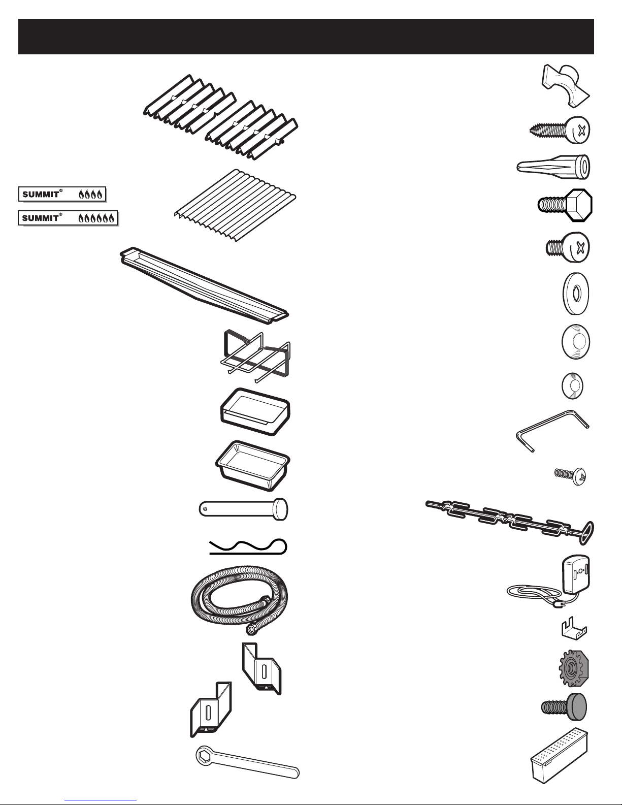
PARTS LIST (CONTINUED)
Flavorizor
Stainless Steel
Cooking Grates
®
Bars - 2 Sets
4B
6B
Bottom Tray - 1
Catch-Pan Holder - 1
- 2
- 3
Wrench - 1
x10 Sheet Metal Screws - 3
Plastic Anchors - 3
1/2 inch Bolts
(1/4 x 20 x 1/2 inch Bolt) - 8
#10-32 x 1/4 inch Steel Screws - 5
Nylon Washer - 8
1/2" Flare Gasket - 2
Catch-Pan - 1
Disposable Drip Pans - 2
Hinge Pin- 2
Hair Pin Cotter- 2
Corrugated gas line - 1
Right Front Vent Clip - 1
3/8" Flare Gasket - 2
Handle - 2
Handle Hardware - 4
Rotisserie - 1
Rotisserie Motor - 1
Rotisserie Bracket - 1
Keps Nuts (1/4 x 20 Blk Zinc) - 2
Left Front Vent Clip - 1
7/16 inch Wrench - 1
Rotisserie Bracket Hardware- 2
Smoker - 1
Page 5
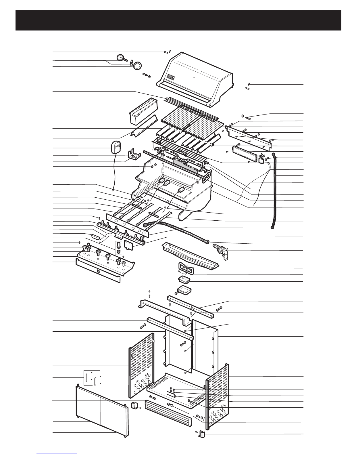
EXPLODED VIEW - PLATINUM D4
5
5340501 - Summit® Platinum D4 NG Built-In 091905
1
2
3
38
4
39
10
11
12
13
14
15
16
17
18
19
20
21
22
23
24
25
26
27
5
6
7
8
9
40
41
42
43
44
45
46
47
48
49
50
51
52
53
54
55
56
57
58
59
60
61
62
63
64
65
28
29
30
31
32
33
34
35
36
37
66
67
68
69
70
71
72
73
74
75
76
77
Page 6

6
EXPLODED VIEW LIST - PLATINUM D4
1. Hinge Pin
2. Thermometer Hardware
3. Thermometer Bezel
4. Warm-Up
™
Basket
5. Smoker Assembly
6. Flavorizer
®
Bar Assembly w/ Smoker
7. Smoker Box Chip Grate
8. Rotisserie Motor
9. Motor Bracket
10. Motor Bracket Screw
11. 1/4 - 20 inch Keps Nut
12. Smoker Electrode Assembly
(10 1/2 inch wire)
13. Electrode Assembly (8 3/4 inch wire)
14. Crossover
®
Tube
15. Smoker Burner Tube
16. Left Burner Tube
17. 10 - 24 x 1/2 inch Black Screw
18. Manifold
19. Negative Ignition Switch Wire
20. Positive Ignition Switch Wire
21. Four Output Ignition Module Assembly
22. Ignition Switch Button Assembly
23. 10 - 24 x 1/2 inch Black Screw
24. Small Control Knob
25. Control Knob
26. Control Panel
27. Front Panel
28. Vent Cover Assembly
29. Front Frame Rail
30. Left Rear Panel
31. Left Panel
32. Handle Assembly
33. Bottom Shelf
34. Toe Kick Vent
35. Left Vent Bracket
36. Left Door Assembly
37. Right Door Assembly
38. Hair Pin Cotter
39. Lid Assembly
40. 1/4 - 20 x 1 1/4 inch Bolt
41. IR Rain Cover Hardware
42. 12 inch Cook Grate
43. IR Rain Cover
44. 10 - 24 x 1/2 inch Stainless Steel Screw
45. Right Flavorizer® Bar Assembly
46. IR Burner
47. IR Cover Box
48. Warming Rack
49. Thermocouple
50. IR Gas Line
51. IR Electrode Wire
52. Rotisserie Fork Screw
53. Rotisserie Fork
54. Rotisserie Shaft
55. Cookbox Assembly
56. Electrode Assembly (16 1/4 inch wire)
57. Right Burner Tube
58. Heat Shield
59. Battery Shield Assembly
60. Main Gas Line
61. Bulkhead Assembly
62. Bottom Tray
63. Summit Catch Pan Holder
64. Summit Catch Pan
65. Summit Drip Pan
66. Rear Frame Rail
67. Rear Vent Hardware
68. Rear Panel Hardware
69. Right Rear Panel
70. Right Panel
71. 10 -16 x 3/4 Screw w/ Washer
72. Plastic Plug
73. Door Stop
74. Door Bushing
75. Door Plug
76. 1/4 - 20 x 1/2 inch Black Bolt
77. Right Vent Bracket
Page 7

EXPLODED VIEW - PLATINUM D6
7
10
11
12
13
14
15
16
17
18
19
20
21
22
23
24
25
26
27
28
29
30
31
1
2
3
4
5
6
7
8
9
5390501 - Summit® Platinum D6 NG Built-In 092005
42
43
44
45
46
47
48
49
50
51
52
53
54
55
56
57
58
59
60
61
62
63
64
65
66
67
68
69
70
32
33
34
35
36
37
38
39
40
41
71
72
73
74
75
76
77
78
79
Page 8

8
EXPLODED VIEW LIST - PLATINUM D6
1. Hinge Pin
2. Thermometer Hardware
3. Thermometer Bezel
4. Warm-Up™ Basket
5. 8 inch Cooking Grate
6. Smoker Assembly
7. Smoker Box Chip Grate
8. Flavorizer® Bar Assembly w/ Smoker
9. Rotisserie Fork
10. Rotisserie Motor
11. Motor Bracket
12. Motor Bracket Screw
13. 1/4 - 20 inch Keps Nut
14. Smoker Electrode Assembly
(10 1/2 inch wire)
15. Electrode Assembly (8 3/4 inch wire)
16. Crossover® Tube
17. Smoker Burner Tube
18. Left Burner Tube
19. Right Burner Tube
20. 10 - 24 x 1/2 inch Black Screw
21. Manifold
22. Negative Ignition Switch Wire
23. Positive Ignition Switch Wire
24. Six Output Ignition Module Assembly
25. Ignition Switch Button Assembly
26. 10 - 24 x 1/2 inch Black Screw
27. Small Control Knob
28. Control Knob
29. Control Panel
30. Front Panel
31. Vent Cover Assembly
32. Front Frame Rail
33. Left Rear Panel
34. Handle Assembly
35. Left Panel
36. Door Stop
37. Bottom Shelf
38. Left Vent Bracket
39. Toe Kick Vent
40. Left Door Assembly
41. Right Door Assembly
42. Hair Pin Cotter
43. Lid Assembly
44. 1/4 - 20 x 1 1/4 inch Bolt
45. 12 inch Cook Grate
46. IR Rain Cover Hardware
47. Right Flavorizer® Bar Assembly
48. IR Rain Cover
49. 10 - 24 x 1/2 inch Stainless Steel Screw
50. Warming Rack
51. Rotisserie Fork Screw
52. IR Burner
53. IR Cover Box
54. Thermocouple
55. IR Gas Line
56. Rotisserie Shaft
57. IR Electrode Wire
58. Cookbox Assembly
59. Electrode Assembly (16 1/4 inch wire)
60. Electrode Assembly (25 1/2 inch wire)
61. Heat Shield
62. Main Gas Line
63. Battery Shield Assembly
64. Bulkhead Assembly
65. Bottom Tray
66. Summit Catch Pan Holder
67. Summit Catch Pan
68. Summit Drip Pan
69. Rear Frame Rail
70. Rear Vent Hardware
71. Rear Panel Hardware
72. Right Rear Panel
73. Right Panel
74. 10 -16 x 3/4 Screw w/ Washer
75. Plastic Plug
76. Door Bushing
77. Door Plug
78. 1/4 - 20 x 1/2 inch Black Bolt
79. Right Vent Bracket
Page 9

ASSEMBLY
9
1
2
1
2
1
Arrow stickers on
Frame Rail (1) and
Left Side Panel (2)
should point toward
each other (shown
above). Door Stop
Bracket (3) should
3
be positioned as
shown (left).
2
ATTENTION!
Do not fully tighten screws.
Clips should slide freely
when installed
Page 10

10
ASSEMBLY
3
4
Page 11

5
ASSEMBLY
11
Page 12

12
6
ASSEMBLY
CAUTION: Use two people to lift and install the Summit® Built-In frame assembly.
a.) Lift the frame assembly into the “island” structure opening. Make sure the frame is resting level on the fi nished surface of
the structure.
b.) Adjust the Front Vent to rest squarely on ground.
c.) Apply a bead of silicone sealant (1) around the perimeter and front edges of the grill that are in contact with the “island”
structure. This will prevent moisture seepage. The sealant you use must have a temperature rating above 120°F (48.8° C).
Any Surface
24 inches (610mm)
a.
c.
(1)
24 inches
(610mm)
24 inches
(610mm)
Note: For a countertop treatment
Recommended 3/4 inch (19.1 mm)
overhang. Notch front edge for
frame to fully slide in.
Frame
Any Surface
24 inches (610mm)
Frame
24 inches
(610mm)
24 inches
(610mm)
b.
Page 13

7
ASSEMBLY
13
4B
6B
(1)
(2)
(3)
Page 14

14
ASSEMBLY
8
(1)
4B
6B
(2)
Page 15

ASSEMBLY
15
9
4B
6B
a
Match Holder
b
c
Page 16

16
10
ASSEMBLY
1/4" Drill Bit
11
Page 17

12
13
ASSEMBLY
17
14
15
Page 18

18
GAS SUPPLY
BUILT-IN GAS LINE LOCATIONS
Note: Leave an access in the “island” structure for gas supply and regulator
service that is not inside the grill structure. Weber
regulator access door (part # 36311) available from your dealer or call
Customer Service at 1-800-446-1071.
Note: Area should be kept clear of sharp, jagged, or extremely abrasive
surfaces to avoid possible damage to gas supply lines. Exercise caution when
pulling gas lines through built-in structure.
3
3
"
/
4
1
6
/
Gas Inlet
"
4
®
has a gas line and
Plan View Left Side
A (3
1
B (6
")
/
4
C
3
")
/
4
Gas Inlet
Side view
TYPICAL NATURAL GAS SUPPLY INSTALLATION
We recommend that this installation be done by a LICENSED professional.
GENERAL SPECIFICATIONS FOR PIPING
Note - Contact your local municipality for building codes regulating outdoor
gas grill installations. In absence of Local Codes, you must conform to the
latest edition of National Fuel Gas Code ANSI Z223.1/NFPA54.
• This grill is designed to operate at 4.5 inches of water column pressure.
• A manual shut-off valve must be installed outdoors, and be accessible,
not in the “built-in” structure. An additional manual shut-off valve indoors
should be installed in the branch fuel line in an accessible location near
the supply line.
CAUTION: If young children are in the area, a
locking valve should be considered.
• Pipe compound should be used which is resistant to the action of liquid
propane gas when gas connections are made.
• The gas connections must be fi rmly attached to a rigid, permanent
construction.
Note: The information provided in this manual is general for typical
installations. We cannot cover all possible installation ideas. We recommend,
prior to installation, that you contact your municipality for local building codes
and your local fi re department for installation verifi cation.
If you have any questions, contact Customer Service at 1-800-446-1071.
Built-In Gas Line Dimensions
Silver Gold Tolerances
A
B
Dimensions
C
Table
10-1
Nominal
Iron Pipe
Size
(Inches)
1/4 .364 32 22 18 15 14 12 11 11 10 98876
3/8 .493 72 49 40 34 30 27 25 23 22 21 18 17 15 14
1/2 .622 132 92 73 63 56 50 46 43 40 38 34 31 28 26
3/4 .824 278 190 152 130 115 105 96 90 84 79 72 64 59 55
1 1.049 520 350 285 245 215 195 180 170 160 150 130 120 110 100
1 1/4 1.380 1050 730 590 500 440 400 370 350 320 305 275 250 225 210
1/12 1.160 1600 1100 890 760 670 610 560 530 490 460 410 380 350 320
2 2.067 3050 2100 1650 1450 1270 1150 1050 990 930 870 780 710 650 610
2 1/2 2.469 4800 3300 2700 2300 2000 1850 1700 1600 1500 1400 1250 1130 1050 980
3 3.068 8500 5900 4700 4100 3600 3250 3000 2800 2600 2500 2200 2000 1850 1700
4 4.026 17500 12000 9700 8300 7400 6800 6200 5800 5400 5100 4500 4100 3800 3500
3
3
"3
/
4
1
6
"6
/
4
1
"2
/
2
2
Maximum Capacity of Pipe in Cubic Feet of Gas per Hour for Gas Pressures of 0.5 psi or Less and a Pressure Drop of 0.3 Inch
Internal
Diameter
(Inches)
© 1997 National Fire Protection Association, Inc,. and International Approval Services - U.S., Inc. All Rights Reserved.
10 20 30 40 50 60 70 80 90 100 125 150 175 200
3
"" +
/
4
1
"+
/
4
1
"+
/
2
1
" -
/
8
1
" -
/
8
1
" -
/
8
Water Column. (Based on a 0.60 Specifi c Gravity Gas)
1
"
/
8
1
"
/
8
1
"
/
8
Length of Pipe (Feet)
Page 19

GAS SUPPLY
19
GAS LINE PIPING
• Refer to the piping chart at the bottom of previous page.
• The corrugated gas line from the manifold is 58 inches long. Do not
extend the gas line.
• We have provided the means to make an SAE 45° fl are connection. Do
not use pipe sealant on this connection.
• If the length of line required does not exceed 50 feet, use a 5/8” O.D.
tube. One size larger should be used for lengths greater than 50 feet.
Refer to piping chart.
• Gas piping may be copper tubing, type K or L; polyethylene plastic
tube, with a minimum wall thickness of .062 inch; or standard weight
(schedule 40) steel or wrought iron pipe.
• Copper tubing must be tin-lined if the gas contains more than 0.3
grams of hydrogen sulfi de per 100 cubic feet of gas.
• Plastic tubing is suitable only for outdoor, underground use.
• Gas piping in contact with earth, or any other material which may
corrode the piping, must be protected against corrosion in an approved
manner.
• Underground piping must have a minimum of 18” cover.
TEST CONNECTIONS
All connections and joints must be thoroughly tested for leaks in accordance
with local codes and all listed procedures in the latest edition of the National
Fuel Gas Code ANSI Z223.1/NFPA 54.
DANGER
Do not use an open fl ame to check for gas
leaks. Be sure there are no sparks or open
fl ames in the area while you check for gas
leaks. This will result in a fi re or explosion
which can cause serious bodily injury or
death, and damage to property.
CONNECT GAS SUPPLY
A 58 inch corrugated gas line is supplied with the grill. This line needs to pass
through the gas inlet opening to the main gas supply.
1) Connect the corrugated gas line to the regulator (a). Use the 1/2” fl ared
gasket (1) to ensure proper seal.
(b) Shows the gas line and regulator assembled.
2) Uncap the fl are fi tting connection off the regulator.
3) Hard pipe the gas supply to the inlet of the regulator. Refer to “Typical
Gas Supply Installation”.
top view
Cap
(Optional Side Burner)
Hard piped
gas supply
Corrugated Gas Line
to Manifold
(1)
Regulator
a.
top view
Cap
(Optional Side Burner)
Hard piped
gas supply
Corrugated Gas Line
to Manifold
Regulator
b.
ATTENTION: This product has been safety tested and
is only certifi ed for use in a specifi c country. Refer to
label located on outer carton for country designation.
These parts may be gas carrying or gas burning components. Please
contact Weber-Stephen Products Co., Customer Service Department for
genuine Weber-Stephen Products Co. replacement part(s) information.
WARNING: Do not attempt to make any repair to
gas carrying or gas burning components without
contacting Weber-Stephen Products Co., Customer
Service Department. Your actions, if you fail to follow
this product Warning, may cause a fi re or an explosion
resulting in serious personal injury or death and damage
to property.
Page 20

20
®
®
®
®
®
®
GAS SUPPLY
4) Connect the corrugated gas line to the manifold located on the right hand
side of grill under the control panel. Use the 1/2” fl ared gasket (1) to
ensure proper seal.
Note: Leave an access in the “island” structure for gas supply and regulator
service not inside the grill structure. Weber® has a gas line and regulator
access door (part # 36311) available from your dealer or call Customer
Service at 1-800-446-1071.
OR
top view
(1)
VENTILATION
WARNING: Air holes must be provided in the structure
at the top and bottom to provide ventilation in the event of
a gas leak.
Air holes can be located in a low visibility area and should be protected by
screening material to prevent rodents and insects from entering the structure.
Air holes will also help dry moisture.
Summit® Built-In cabinet vents are available from your dealer or call Customer
Service at 1-800-446-1071.
Right Side
Left Side
Front View
Note: These drawings are only a reference.
• Cross ventilation must be incorporated in the supporting structure. We
recommend a minimum of 100 square inches of venting per side.
• Vents should be on two sides of the structure.
• The above drawings are for reference only.
• Location of the vents should be from the center, outward.
• Locate the vents at both the bottom of the structure and at the top of the
structure.
• The bottom vents should be as close to ground level as possible. Make
sure the vent area is not blocked by interior supports of the structure.
• We recommend vents with screens.
• Access doors to the structure are not considered vents.
• Clean the vents periodically.
DANGER: Failure to follow recommended minimum
venting instructions can cause gas to collect in the
structure in the event of a gas leak. This may result in a
fi re or an explosion which can cause serious bodily injury
or death, and damage to property.
WEBER-STEPHEN PRODUCTS CO.
www.weber.com
©2003 The following trademarks are registered in the name of Weber-Stephen Products Co., an Illinois corporation, located at 200 East Daniels Road, Palatine, Illinois 60067 U.S.A.
Australia; Smokey Joe, Weber, Kettle Silhouette
tion, Botswana; Weber, Canada; Smokey Joe, Genesis, China; Kettle Silhouette
Smokey Joe, Weber, One-Touch, Germany; Smokey Joe, Weber, One-Touch, Greece; Smokey Joe, Ireland; Kettle Silhouette
Joe, Weber, Korea; Smokey Joe, Weber, New Zealand; Weber, Smokey Joe, Nigeria; Weber, Norway; Smokey Joe, Weber, Portugal; Weber, South Africa: Smokey Joe, Weber, Kettle
Confi guration, Spain; Smokey Joe, Weber, Sweden; Kettle Silhouette
One-Touch, U.S.A..; Kettle Confi guration, Kettle Silhouette
vorizer, Crossover, Flamgo, Performer, Rapidfi re, Tuck ‘N Carry, Jumbo Joe, Bar-B-Kettle, Master-Touch, Spirit, Grill Out, Summit, Platinum, 1-800-Grill-Out, Ranch, Matchless Flame,
Zimbabwe; Weber, Kettle Confi guration, Kettle Silhouette
, Genesis, Austria; Kettle Silhouette®, Smokey Joe, Weber, Benelux; Kettle Silhouette®, Smokey Joe, Weber, Compact Grill Confi gura-
, Smokey Joe, Switzerland; Kettle Silhouette®, Smokey Joe, Weber, United Kingdom; Smokey Joe, Weber, Weber
, Smokey Joe, Weber, One-Touch, Firespice, Go-Anywhere, U.S.A.;Kettle Confi guration, Kettle Silhouette, Genesis, Fla-
.
, Denmark; Kettle Silhouette®, Smokey Joe, Weber, Finland; Smokey Joe, France; Kettle Silhouette®,
®
, Smokey Joe, Italy; Smokey Joe, Weber, Japan; Smokey
 Loading...