

Page 1
SUMMIT 475 & 675
Natural Gas Barbecues
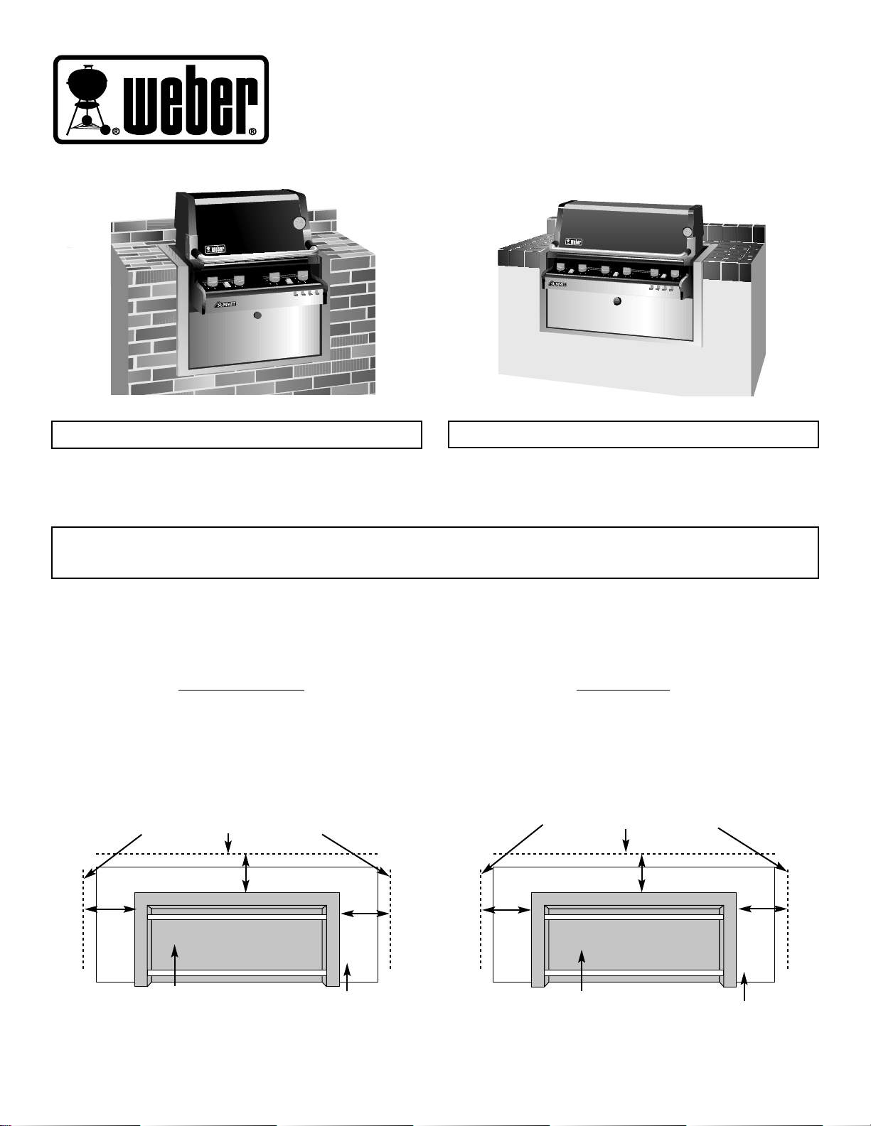
Summit 475 NG
Summit 675 NG
THIS GAS APPLIANCE IS DESIGNED FOR OUTDOOR USE ONLY.
GENERAL INFORMATION
BUILT-IN CONSTRUCTION GENERAL INFORMATION
WARNING
A Weber-Stephen Products Co. insulated sleeve must be used for any built-in installation.
CLEARANCE FROM COMBUSTIBLE SURFACES OR
STRUCTURES
Warning: Clearance from the outside walls of the sides and
back of the insulated sleeve must be a minimum of 24
inches from a combustible surface. Measure from the
outside wall of the insulated surface to the combustible
surface. Figure 2. Refer to “Install Gas Supply” on page 2
before starting installation.
Figure 2
Figure 1
CLEARANCE FROM NON-COMBUSTIBLE SURFACES OR
STRUCTURES
Warning: Clearance from the outside walls of the sides and
back of the insulated sleeve must be a minimum of 6 inches
from a non-combustible surface. Measure from the outside
wall of the insulated surface to the non-combustible
surface. Figure 1. Refer to “Install Gas Supply” on page 2
before starting installation.
COMBUSTIBLE SURFACE
24 inches
24 inches
24 inches
NON- COMBUSTIBLE SURFACE
6 inches
6 inches
6 inches
WARNING: All countertop finished surfaces must be
constructed of a noncombustible material.
WARNING: All countertop finished surfaces must be
constructed of a noncombustible material.
Countertop
Countertop
Insulated sleeve
Insulated sleeve
LOCA TING YOUR BARBECUE
When determining a suitable location for your barbecue installation, give attention to concerns such as exposure to wind, proximity to
traffic paths, and keeping any gas supply lines as short as possible. Never locate the Weber Gas Barbecue in a garage, breezeway,
shed, under an unprotected overhang, or other enclosed area. Locate the barbecue and structure so there is enough room to safely
evacuate the area in case of a fire.
THIS GAS APPLIANCE IS DESIGNED FOR OUTDOOR USE ONLY.
98251 3/99
Page 2
2
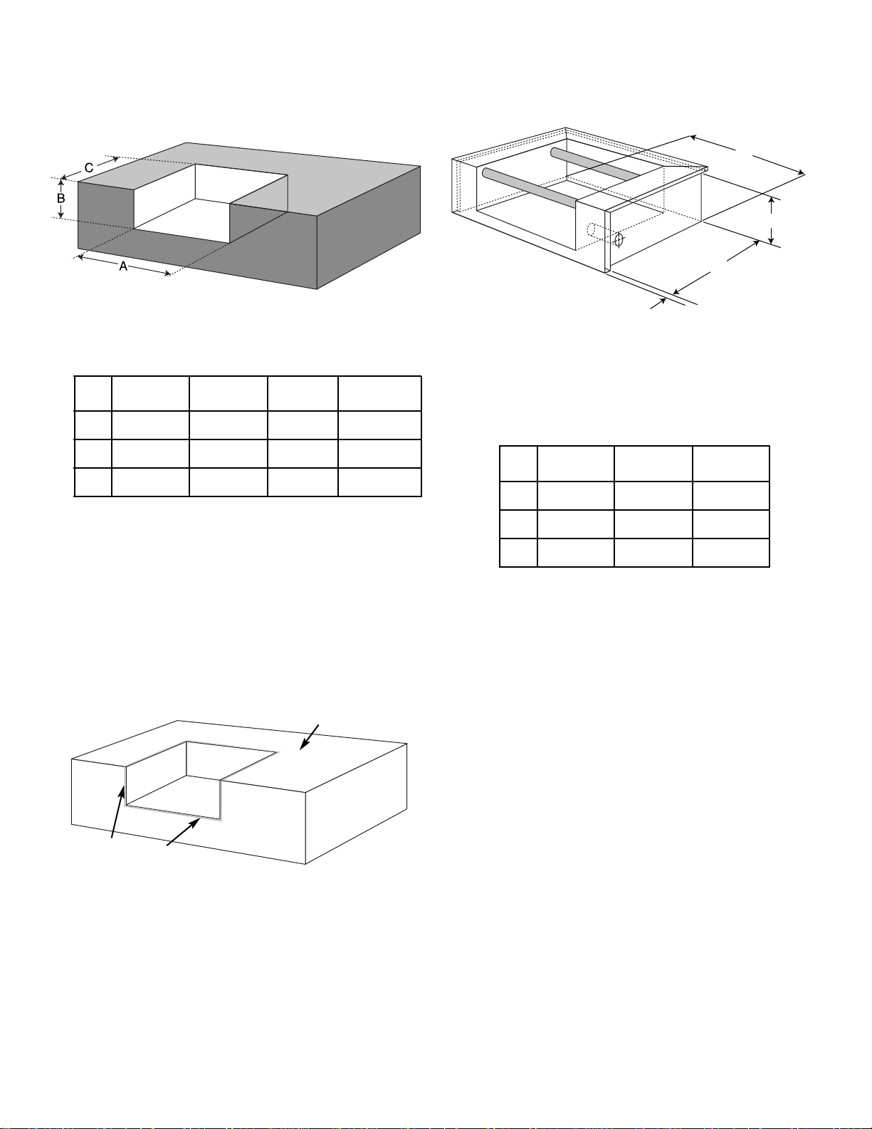
BUILT-IN STRUCTURE
CUTOUT DIMENSIONS
Side
475 675 Burner Tolerances
A31
5
⁄8”43
5
⁄8”10
3
⁄4”
B21
1
⁄8”21
1
⁄8”4
1
⁄2”
C 25” 25” 24”
WT 240 285 40
DIMENSIONS
+ 3⁄16”
- 0
+ 3⁄32”
- 0
+ 3⁄16”
-0
BUILT-IN CUTOUT DIMENSIONS
BUILT-IN STRUCTURE
SLEEVE DIMENSIONS
A
B
C
.625
TYP. TRIM
OVERHANG
DEPTH
HEIGHT
WIDTH
475 675 Tolerances
A31
1
⁄2”43
1
⁄2”
B21
1
⁄16”21
1
⁄16”
C2415⁄16”24
15
⁄16”
WT 240 285
DIMENSIONS
+ 1⁄4”
- 0
+ 3⁄16”
- 0
+ 3⁄16”
-0
BUILT-IN INSULATED SLEEVE
DIMENSIONS
Weight (expressed in pounds) represents the total weight
of the insulated sleeve and the cooking unit and does not
include the permanent structure housing the sleeve.
Specified insulated sleeve dimensions “A through C”
reflect the dimension to the mounting surface of the trim
excluding the .625 trim overhang.
If the supporting structure is going to have an
electrical outlet for a rotisserie, it should be on the
left side of the structure.
WARNING: Air holes must be provided in the
structure at the top and bottom to provide ventilation
in the event of a gas leak.
Air holes can be located in a low visibility area and should
be protected by screening material to prevent rodents and
insects from entering the structure. Air holes will also help
dry moisture.
Before installing the sleeve, lay a bead of silicon sealant
around the top perimeter and front sides of the structure
in the areas that the flanges of the sleeve will rest. This
will prevent moisture seepage. The sealant you use must
have a temperature rating above 120°F. If necessary,
caulk between the flange of the sleeve and finished
countertop surface.
WARNING: All countertop finished surfaces must be
constructed of a noncombustible material.
Countertop
Silicon sealant
Figure 3
Figure 4
Figure 5
Weight (expressed in pounds) represents the total weight
of the insulated sleeve and the cooking unit and does not
include the permanent structure housing the sleeve.
The sleeve must be supported from the bottom.
Recommended cutout dimensions “A through C” include a
nominal clearance dimension to facilitate installation. Any
additional clearance must be within tolerances shown or
fit-up of sleeve and built-in structure may be adversely
affected.
All dimensions are to finished surfaces.
All dimensions are to finished surfaces.
Page 3
3
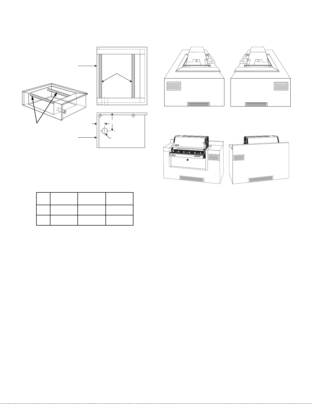
BUILT-IN SLEEVE GAS
LINE LOCATIONS
A
B
C
Support tubes
Front of sleeve
Front of sleeve
Plan view
Right side view
475 675 Tolerances
A 5.0” 5.0”
B 10.1” 10.1”
C 2.5” 2.5”
DIMENSIONS
+ 1⁄16
- 1⁄16
+ 1⁄16
- 1⁄16
+ 1⁄32
- 1⁄32
BUILT-IN SLEEVE GAS LINE
LOCATIONS
The dimensions shown indicate the location of the gas
line inlet flange in the insulated sleeve. The support
members of the built-in structure must not impede
passage of the gas lines.
Area should be kept clear of sharp, jagged, or extremely
abrasive surfaces to avoid possible damage to gas supply
lines. Exercise caution when pulling gas lines through
built-in structure.
Note: Leave an access in the structure for gas supply
and regulator service.
Figure 6
Support tubes
■ Cross ventilation must be incorporated in the
supporting structure. We recommend a minimum of
100 square inches of venting per side.
■ Vents should be on two sides of the structure.
Figures 5 and 6 are references only.
■ Location of the vents should be from the center,
outward.
■ Locate the vents at both the bottom of the structure
and at the top of the structure.
■ The bottom vents should be as close to ground level
as possible. Make sure the vent area is not blocked
by interior supports of the structure.
■ We recommend vents with screens.
■ Access doors to the structure are not considered vents.
■ Clean the vents periodically.
DANGER: Failure to follow recommended minimum
venting instructions can cause gas to collect in the
structure in the event of a gas leak.This may result in
a fire or an explosion which can cause serious bodily
injury or death, and damage to property.
Note:These drawings are only a reference.
VENTILATION
View of left side View of right side
View of front side View of back side
Figure 7
Figure 8
Page 4

4
TYPICAL GAS SUPPLY
INSTALLATION
Gas line piping
■ If the length of line required does not exceed 50 feet,
use a 5/8" O.D. tube. One size larger should be used
for lengths greater than 50 feet.
■ Gas piping may be copper tubing, type K or L;
polyethylene plastic tube, with a minimum wall
thickness of .062 inch; or standard weight (schedule
40) steel or wrought iron pipe.
■ Copper tubing must be tin-lined if the gas contains
more than 0.3 grams of hydrogen sulfide per 100 cubic
feet of gas.
■ Plastic tubing is suitable only for outdoor,
underground use.
■ Gas piping in contact with earth, or any other material
which may corrode the piping, must be protected
against corrosion in an approved manner.
■ Underground piping must have a minimum of 18" cover.
Test connections
All connections and joints must be thoroughly tested for
leaks in accordance with local codes and all listed
procedures in the latest edition of ANSI Z223.1.
DANGER
Do not use an open flame to check for gas
leaks. Be sure there are no sparks or open
flames in the area while you check for gas
leaks. This will result in a fire or explosion
which can cause serious bodily injury or death,
and damage to property.
WE RECOMMEND THAT THIS INSTALLATION BE
DONE BY A LICENSED PROFESSIONAL.
General Specifications for Piping
Note - Contact your local municipality for building
codes regulating outdoor gas barbecue installations.
In absence of Local Codes, you must conform to the
latest edition of ANSI Z223.1.
■ This barbecue is designed to operate at 4.5 inches of
water column pressure. Use only the regulator
supplied with the cooking module.
■ A manual shut-off valve must be installed outdoors,
and be accessible, not in the “built-in” structure. An
additional manual shut-off valve indoors should be
installed in the branch fuel line in an accessible
location near the supply line.
CAUTION: If young children are in the area, a locking
valve should be considered.
■ Pipe compound should be used which is resistant to the
action of natural gas when gas connections are made.
■ The gas connections must be firmly attached to rigid,
permanent construction.
The information provided in this manual is general for
typical installations.We cannot cover all possible
installation ideas.We recommend prior to installation
that you contact your municipality for local building
codes and your local fire department for installation
verification.You can also call Weber-Stephen
Products Co. at 1-888-33SUMMIT (1-888-337-8664) and
we will try and answer any questions you may have.
If you have any questions, contact the Weber-Stephen
Customer Service Center at 1-888-33-SUMMIT
(1-888-337-8664).
Page 5

5
BUILT-IN SIDE BURNER
For Summit Natural
Gas Cooking Modules
THIS ACCESSORY MAY BE PURCHASED SEPERATELY.
GENERAL INFORMATION
BUILT-IN CONSTRUCTION GENERAL INFORMATION
WARNING
A Weber-Stephen Products Co. insulated sleeve must be used for any built-in installation.
CLEARANCE FROM COMBUSTIBLE SURFACES OR
STRUCTURES
Warning: Clearance from the outside walls of the sides and
back of the sleeve must be a minimum of 24 inches from a
combustible surface. Measure from the outside wall of the
sleeve to the combustible surface. Figure 2. Refer to “Install
Gas Supply” on page 2 before starting installation.
Figure 2
Figure 1
CLEARANCE FROM NON-COMBUSTIBLE SURFACES OR
STRUCTURES
Warning: Clearance from the outside walls of the sides and
back of the sleeve must be a minimum of 6 inches from a
non-combustible surface. Measure from the outside wall of
the sleeve to the non-combustible surface. Figure 1. Refer to
“Install Gas Supply” on page 2 before starting installation.
COMBUSTIBLE SURFACE
24 inches
24 inches
24 inches
NON- COMBUSTIBLE SURFACE
6 inches
6 inches
6 inches
WARNING: All countertop finished surfaces must be
constructed of a noncombustible material.
WARNING: All countertop finished surfaces must be
constructed of a noncombustible material.
Countertop
Countertop
Insulated sleeve
Insulated sleeve
LOCA TING YOUR SIDE BURNER
When determining a suitable location for your side burner installation, give attention to concerns such as exposure to wind, proximity
to traffic paths, and keeping any gas supply lines as short as possible. Never locate the Weber Gas Side Burner in a garage,
breezeway, shed, under an unprotected overhang, or other enclosed area. Locate the side burner and structure so there is enough
room to safely evacuate the area in case of a fire.
THIS GAS APPLIANCE IS DESIGNED
FOR OUTDOOR USE ONLY.
Page 6

6
BUILT-IN STRUCTURE
CUTOUT DIMENSIONS
Side Burner Tolerances
A10
3
⁄
4”
B4
1
⁄
2”
C 24”
WT 40
DIMENSIONS
+ 3⁄16”
- 0
+ 3⁄32”
- 0
+ 3⁄16”
-0
BUILT-IN CUTOUT DIMENSIONS
BUILT-IN STRUCTURE
SLEEVE DIMENSIONS
Side burner Tolerances
A1019⁄32”
B4
9
⁄64”
C2325⁄32”
WT 40
DIMENSIONS
+ 1⁄4”
- 0
+ 1⁄8”
- 0
+ 1⁄4”
-0
BUILT-IN INSULATED SLEEVE
DIMENSIONS
Weight (expressed in pounds) represents the total weight
of the sleeve and the cooking unit and does not include
the permanent structure housing the sleeve.
Specified sleeve dimensions “A through C” reflect the
dimension to the mounting surface of the trim excluding
the overhang.
WARNING:Air holes must be provided in the structure
at the top and bottom to provide ventilation in the event
of a gas leak.
Air holes can be located in a low visibility area and should
be protected by screening material to prevent rodents and
insects from entering the structure. Air holes will also help
dry moisture.
If you are going to use a rotisserie with the cooking module,
make sure you space the side burner far enough away to
facilitate its use.
Before installing the sleeve, lay a bead of silicon sealant
around the top perimeter and front sides of the structure
in the areas that the flanges of the sleeve will rest. This
will prevent moisture seepage. The sealant you use must
have a temperature rating above 120°F. If necessary,
caulk between the flange of the sleeve and finished
countertop surface.
WARNING: All countertop finished surfaces must be
constructed of a noncombustible material.
Countertop
Silicon sealant
Figure 3
Figure 4
Figure 5
Weight (expressed in pounds) represents the total weight
of the sleeve and the cooking unit and does not include
the permanent structure housing the sleeve.
The sleeve must be supported from the bottom.
Recommended cutout dimensions “A through C” include a
nominal clearance dimension to facilitate installation. Any
additional clearance must be within tolerances shown or fitup of sleeve and built-in structure may be adversely affected.
A
B
C
DEPTH
HEIGHT
WIDTH
All dimensions are to finished surfaces.
Page 7

7
BUILT-IN CONSTRUCTION GENERAL INFORMATION
WARNING
A Weber-Stephen Products Co. factory
installed sleeve must be used for any
built-in installation.
CLEARANCE FROM COMBUSTIBLE SURFACES OR
STRUCTURES
Warning: Clearance from the outside walls of the
sides and back of the sleeve must be a minimum of
24 inches from a combustible surface. Measure from
the outside wall of the sleeve to the combustible
surface. Figure 2. Refer to “Install Gas Supply”on
page 2 before starting installation.
Figure 2
Figure 1
LOCA TING Y OUR SIDE BURNER
When determining a suitable location for your side burner
installation, give attention to concerns such as exposure
to wind, proximity to traffic paths, and keeping any gas
supply lines as short as possible. Never locate the Weber
Gas Side Burner in a garage, breezeway, shed, under an
unprotected overhang, or other enclosed area. Locate the
side burner and structure so there is enough room to
safely evacuate the area in case of a fire.
CLEARANCE FROM NON-COMB
USTIBLE SURFACES
OR STRUCTURES
Warning: Clearance from the outside walls of the
sides and back of the sleeve must be a minimum of 6
inches from a non-combustible surface. Measure from
the outside wall of the sleeve to the non-combustible
surface. Figure 1. Refer to “Install Gas Supply”on
page 2 before starting installation.
COMBUSTIBLE SURFACE
24 inches
24 inches
24 inches
NON- COMBUSTIBLE SURFACE
6 inches
6 inches
6 inches
WARNING: All countertop finished surfaces must be
constructed of a noncombustible material.
WARNING: All countertop finished surfaces must be
constructed of a noncombustible material.
Countertop
Countertop
Sleeve
Sleeve
Page 8

8
TYPICAL GAS SUPPLY
INSTALLATION
■ A manual shut-off valve must be installed outdoors,
and be accessible, not in the “built-in” structure. An
additional manual shut-off valve indoors should be
installed in the branch fuel line in an accessible
location near the supply line.
CAUTION: If young children are in the area, a locking
valve should be considered.
■ Pipe compound should be used which is resistant to the
action of natural gas when gas connections are made.
■ The gas connections must be firmly attached to rigid,
permanent construction.
The information provided in this manual is general
for typical installations.We cannot cover all possible
installation ideas.We recommend prior to installation
that you contact your municipality for local building
codes and your local fire department for installation
verification.You can also call Weber-Stephen Products
Co. at 1-888-33SUMMIT (1-888-337-8664) and we will try
and answer any questions you may have.
Gas line piping
■ If the length of line required does not exceed 50 feet,
use a 5/8" O.D. tube. One size larger should be used
for lengths greater than 50 feet.
■ Gas piping may be copper tubing, type K or L;
polyethylene plastic tube, with a minimum wall
thickness of .062 inch; or standard weight
(schedule 40) steel or wrought iron pipe.
■ Copper tubing must be tin-lined if the gas contains
more than 0.3 grams of hydrogen sulfide per 100 cubic
feet of gas.
■ Plastic tubing is suitable only for outdoor,
underground use.
■ Gas piping in contact with earth, or any other material
which may corrode the piping, must be protected
against corrosion in an approved manner.
■ Underground piping must have a minimum of 18" cover.
Test connections
All connections and joints must be thoroughly tested for
leaks in accordance with local codes and all listed
procedures in the latest edition of ANSI Z223.1.
DANGER
Do not use an open flame to check for gas
leaks. Be sure there are no sparks or open
flames in the area while you check for gas
leaks. This will result in a fire or explosion
which can cause serious bodily injury or death,
and damage to property.
WE RECOMMEND THAT THIS INSTALLATION BE
DONE BY A LICENSED PROFESSIONAL.
General Specifications for Piping
Note - Contact your local municipality for building
codes regulating outdoor gas barbecue installations.
In absence of Local Codes, you must conform to the
latest edition of ANSI Z223.1.
■ This barbecue is designed to operate at 4.5 inches of
water column pressure. Use only the regulator
supplied with the cooking module.
If you have any questions, contact the Weber-Stephen
Customer Service Center at 1-888-33-SUMMIT
(1-888-337-8664).
BUILT-IN SLEEVE GAS
LINE LOCATIONS
Side Burner Tolerances
A1
19
⁄32”
B8”
DIMENSIONS
+ 1⁄16
- 1⁄16
+ 1⁄16
- 1⁄16
BUILT-IN SLEEVE GAS LINE
LOCATIONS
The dimensions shown indicate the location of the gas line
inlet flange in the sleeve. The support members of the builtin structure must not impede passage of the gas lines.
Area should be kept clear of sharp, jagged, or extremely
abrasive surfaces to avoid possible damage to gas supply
lines. Exercise caution when pulling gas lines through
built-in structure.
Note: Leave an access in the structure for gas supply
and regulator service.
Figure 6
B
A
 Loading...