

Page 1
SUMMITTM450 & 650
LP Gas Barbecues
Step-By-Step Guide
72627 10/25/00
W
E
B
E
R
W
E
B
E
R
W
E
B
E
R
W
E
B
E
R
DANGER
If you smell gas:
1. Shut off gas to the appliance.
2. Extinguish any open flames.
3. Open lid
4. If odor continues, keep away from the
appliance and immediately call your gas
supplier or your fire department.
Leaking gas may cause a fire or explosion
which can cause serious bodily injury or
death, or damage to property.
WARNING:
1. Do not store spare liquid propane
cylinder within 10 feet (3m) of this
appliance.
2. Do not store or use gasoline or other
flammable liquids or vapors within 25 feet
(8m) of this appliance.
WARNING: Follow all leak-check
procedures carefully in this manual prior to
barbecue operation. Do this even if the
barbecue was dealer-assembled.
NOTICE TO INSTALLER: These instructions
must be left with the owner and the owner
should keep them for future use.
THIS GAS APPLIANCE IS DESIGNED FOR
OUTDOOR USE ONLY.OUTDOOR USE
ONLY.
WARNING: Do not try to light this
appliance without reading the "Lighting"
Instructions section of this manual
Page 2
“U” rails (2)
CONTINUE TO REMOVE PACKAGED CONTENTS
2
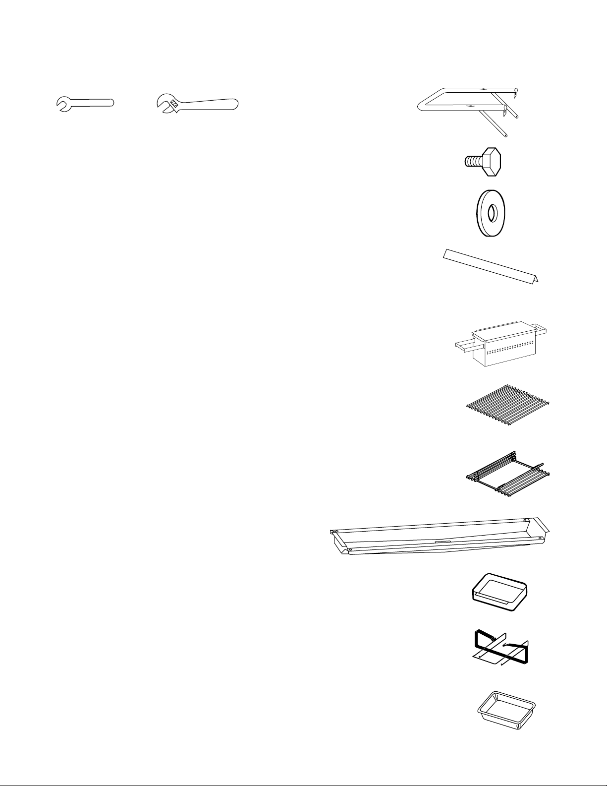
TOOLS NEEDED
SUPPLIES NEEDED
7/16 inch open end or an adjustable wrench
You will need a soap and water solution to check for gas
leaks. (See Step "Check for gas leaks.")
Note - The hardware size of nuts, bolts and screws is
given. For example "1/4-20 x 2 inch bolt" means a bolt
1/4 inch in diameter with 20 threads to the inch, 2 inches
long. On a small screw for example, "6-32 x 1/2 inch
screw" means a number 6 screw, with 32 threads to the
inch, 1/2 inch long.
Bottom tray
Catch pan holder
Catch pan
1/2 inch bolts
(1/4-20 x 1/2 inch bolts) (8)
Nylon washer (8)
Cooking grate
Summit 450 (1)
Summit 650 (2)
Flavorizer bars
Summit 450 (7)
Summit 650 (11)
Steam-N-Chips Smoker
Note: If you use the Steam-NChips Smoker, you will be
removing one of the Flavorizer
bars. You have a full set of
Flavorizer bars to use when not
using the Steam-N-Chips smoker.
Disposable drip pan
Note: Remove all
packaging materials
from the barbecue,
the front, back sides,
inside the barbecue
cart, and the bottom
shipping platform.
Once the packaging
material is removed,
carefully roll the
barbecue off the
shipping platform
and lock the casters.
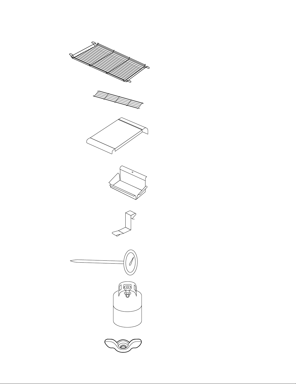
Hinged cooking grate
Page 3
3
REMOVE PACKAGED CONTENTS (CONTINUED)
Cylinder hanger
Stainless steel work surface (2)
Condiment holder (2)
Tool holder (4)
Bottom shelf
Warm-up basket
1/4-20 wing nuts (4)
Thermometer
Page 4
4
a)
b)
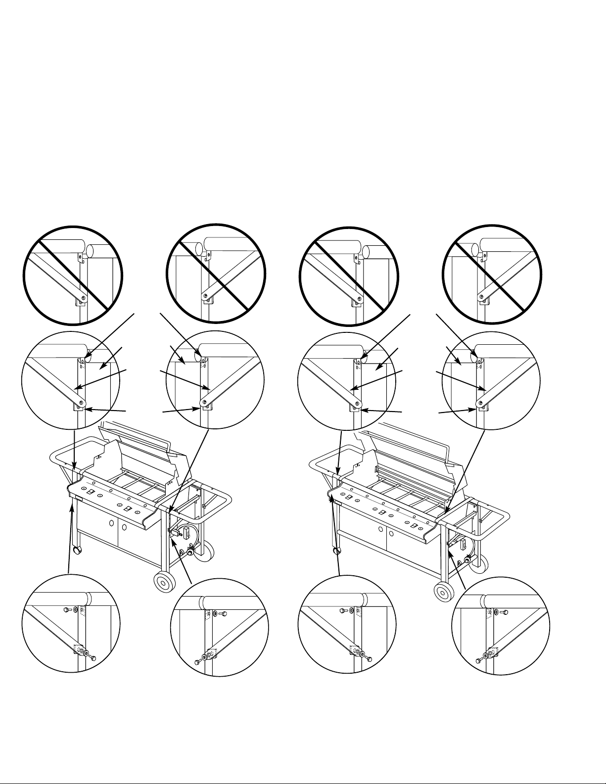
INSTALL “U” RAILS
Figure 1
“U” rail
support
mounts
Tabs
Frame rails
“U” rail
supports
Note: lock the casters before starting assembly.
You will need: two “U” rails, eight 1/4-20 x 1/2 inch bolts,
eight nylon washers, and a 7/16 inch or adjustable wrench.
Insert the tabs of the “U” rail into the frame rails. Make sure
both tabs are inside the frame rails. Figure 1(a) and that the
“U” rail supports are outside of the “U” rail support mounts.
Figure 1(a).
Push the “U” rail down into place on top of the frame rail.
Add a nylon washer to a bolt and start the bolt through the
a)
b)
Figure 1
“U” rail
support
mounts
Tabs
Frame rails
“U” rail
supports
Summit 450
Summit 650
hole of the frame rail into the tab of the “U” rail. Only start the
two bolts. Figure 1(b).
Align the holes of the “U” rail support with the holes in the
“U” rail support mount. Add a washer to a bolt and start the
bolt through the “U” rail support and into the “U” rail support
mount. Figure 1(b). Only start the two bolts.
Once you have started the four bolts per side, use the
7/16 inch or adjustable wrench to tighten the four bolts on
each side of the barbecue.
Page 5
5
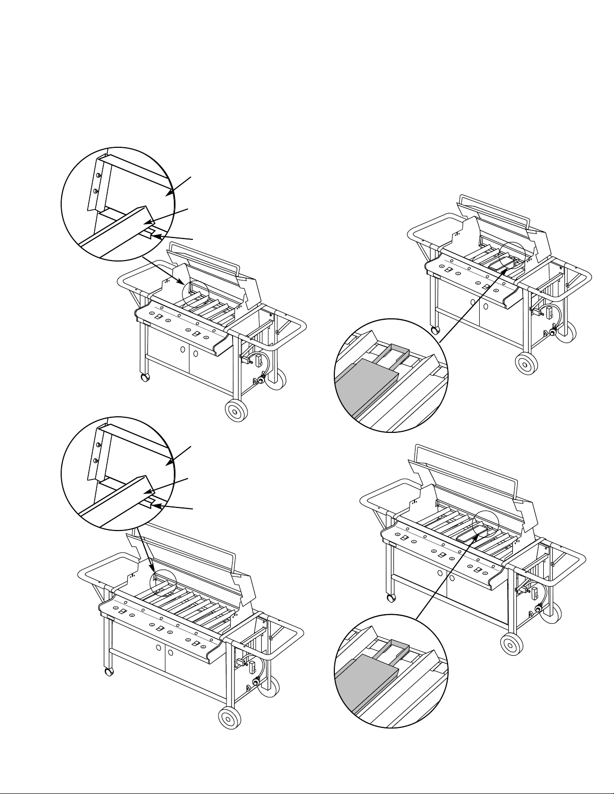
INSTALL STEAM-N-CHIPS SMOKER
You will need: smoker box.
Remove the center Flavorizer bar (the one that is not over
a burner). Set the handles of the Steam-N-Chips smoker
on the Flavorizer bar holder.
Note: For directions on how to use the Steam-N-Chips
smoker, see the Operating Guide.
INSTALL FLAVORIZER BARS
You will need: seven Flavorizer bars.
Set the Flavorizer bars front to back over the burners in the
slots of the Flavorizer Bar/cooking grill support..
Flavorizer Bar/cooking grill
support
Flavorizer Bar
Slot
Flavorizer Bar/cooking grill
support
Flavorizer Bar
Slot
Summit 450
Summit 650
Summit 450
Summit 650
Page 6

6
ADD COOKING GRATES
You will need: (1) cooking grate and (1) Hinged Cooking
Grate .
The cross-rail of the cooking grate goes down. Set the
cooking grates in place next to each other.
WARNING: Use heat-resistant barbecue mitts or
gloves when adding wood to the
Steam-N-Chips Smoker.
Use a barbecue tool to swing open the hinged portions of
the cooking grate.
Summit 450
Summit 650
Summit 450
Summit 650
Page 7
7
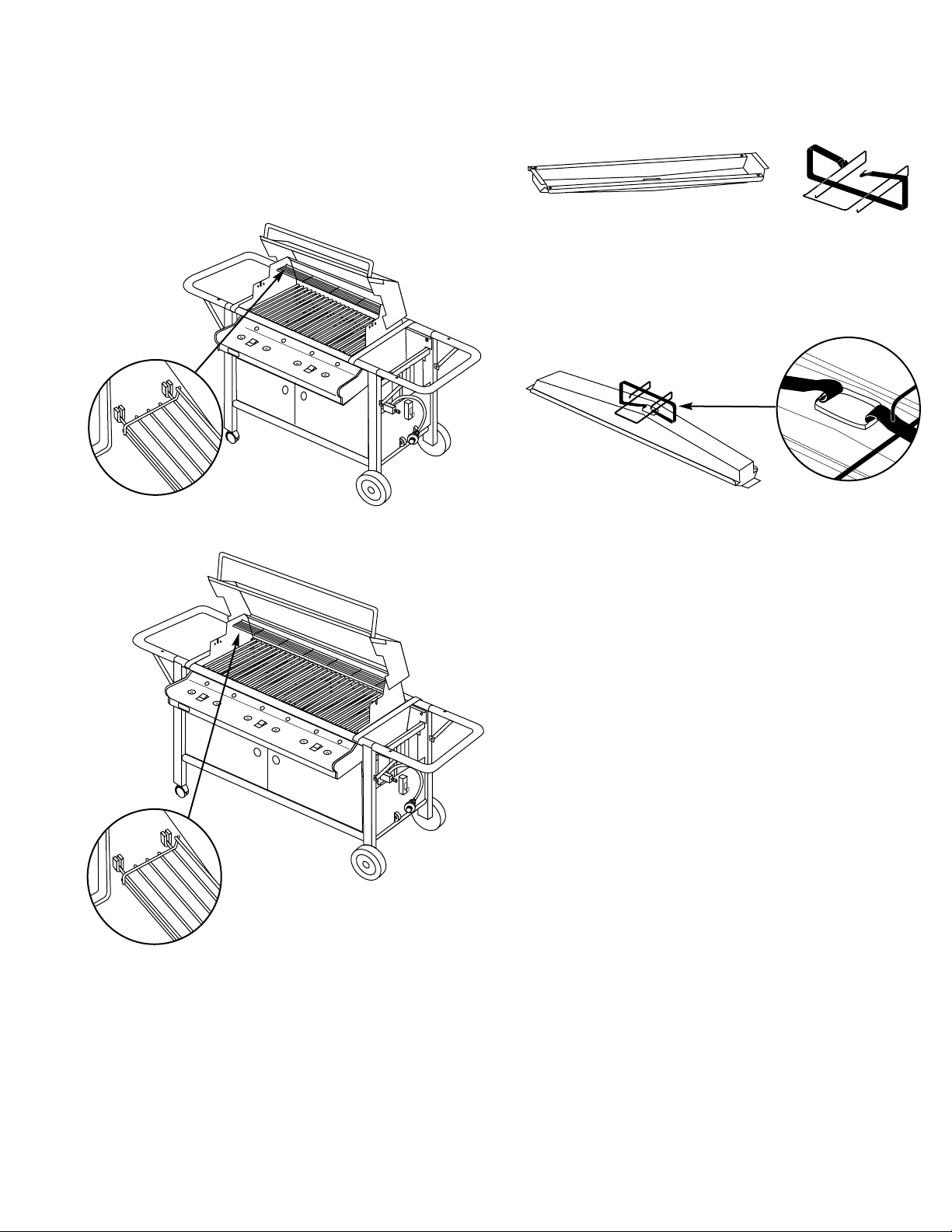
INSTALL WARM-UP BASKET
You will need: warm-up basket.
Install one end of the warm-up basket into the hole on the
right end of the lid and the other end into the slot in the
left end of the lid.
Summit 450
Summit 650
INSTALL BOTTOM TRAY
You will need: Bottom tray, catch pan holder, catch pan,
and one drip pan.
Note: It may be easier to install the catch pan holder by
removing the catch pan from the holder.
Hook the ends of the catch pan holder into the hole in the
bottom tray.
Page 8

8
INSTALL BOTTOM SHELF
Place the bottomshelf under the cart between the frame
supports. Lift up one end of the shelf so it clears the
crosspiece. Continue to lift until the opposite end clears
the opposite crosspiece. Set the shelf in place on both
crosspieces.
8
Slide the bottom tray into the mounting slots under the
bottom of the cooking box with the finger grip of the catch
pan toward you.
CAUTION: Do not line the bottom tray with aluminum
foil. It can cause grease fires by trapping the grease
and not allowing grease to flow into the catch pan.
Put the foil drip pan into the catch pan.
Mounting
slots
View from front of the Cooking Box
Tabs of
bottom tray
Summit 450
Summit 650
Summit 450
Summit 650
Page 9

9
INSTALL CONDIMENT HOLDERS AND WORK SURFACES
Figure 11
You will need: two condiment holders, two stainless steel
work surfaces, and four wing nuts.
Place the condiment holders on the left and right side of
the frame. Figure 11(a). Set the work surfaces over the
condiment holders on both sides of the barbecue. The
studs of the work surface go through the holes in the
top of the condiment holder and through the frame rail.
Thread on the wing nuts on the front and back and
tighten. Figure 11(b).
a)
b)
Studs
underneath
work surfaces
FILL LIQUID PROPANE CYLINDER
Note - The liquid propane cylinder manufacturer is
responsible for the materials, workmanship and
performance of the cylinder. If the cylinder has a defect,
malfunctions, or you have a question regarding the
cylinder, call the cylinder manufacturer’s customer service
center. The phone number is on the warning decal, which
is permanently attached to the cylinder. If the cylinder
manufacturer has not resolved the issue to your
satisfaction, then contact the Customer Service
Representative in your region using the contact
information sheet provided with your manual.
To fill, take the liquid propane cylinder and filler adapter to
an RV center or look up gas-propane in the phone book
for other sources of liquid propane gas.
WARNING: We recommend that your liquid propane
cylinder be filled at an authorized liquid propane gas
dealer by a qualified attendant, who fills the tank by
weight.
IMPROPER FILLING IS DANGEROUS.
Tell your liquid propane dealer that this is a new liquid
propane cylinder. The air must be removed from a new
liquid propane cylinder before the initial filling. Your liquid
propane cylinder dealer is equipped to do this.
The liquid propane cylinder must be installed, transported
and stored in an upright position, and should not be
dropped or handled roughly.
Never store or transport the liquid propane cylinder where
temperatures can reach 125° Fahrenheit (too hot to hold
by hand – for example: do not leave the liquid propane
cylinder in a car on a hot day).
For full instructions on safe handling of liquid propane
cylinders, see Section “Operating”.
CHECKING THE FUEL LEVEL IN YOUR TANK
Check the fuel level by viewing the color indicator
level line on the side of the tank scale.
1) Empty
2) Medium
3) Full
(1)
(2)
(3)
Page 10

10
IMPORTANT LP CYLINDER INFORMATION
Failure to follow these DANGER statements exactly may
result in a fire causing death or serious injury.
DANGER
NEVER store a spare LP Cylinder under or near this
barbecue.
NEVER fill the tank beyond 80% full.
Your Weber gas grill is equipped with a cylinder
supply system designed for vapor withdrawal.
WARNING: Only use this grill outdoors in a wellventilated area. Do not use in a garage, building,
breezeway or any other enclosed area.
The LP cylinder supplied with your barbecue is
equipped with an OPD (Overfilling Prevention Device)
and a QCC1 or Type 1 (CGA810) cylinder connection.
The cylinder connection is compatible with the
barbecue connection.
This is a secondary device to prevent the overfilling of
your LP cylinder. The proper filling methods for the filling
of your cylinder are by weight or volume, as described in
NFPA 58. Please make sure your filling station fills your
LP cylinder by weight or volume. Ask your filling station to
read purging and filling instructions on the LP cylinder
before attempting to fill.
WARNING: Do not exchange the LP tank provided
with your barbecue, unless the exchange LP tank is
equipped with an OPD. Otherwise you will lose the
OPD (Overfilling Prevention Device) feature. If there is
not an LP tank available for exchange equipped with
an OPD, we recommend that you have your LP tank
filled at an authorized LP gas dealer by a qualified
attendant.
Raises up while filling
then stops when full.
CONNECT FILLED LIQUID PROPANE CYLINDER
WARNING: Make sure that the cylinder valve is
closed. Close by turning clockwise.
We utilize various LP tank manufacturers. Some of the
tanks have differing top collar assembles. (The top collar
is the metal protective ring around the valve.) One series
of tanks mount with the valve facing front. The other
tanks mount with the valve facing away from the fuel
scale. These types of tanks are illustrated below.
Hook the liquid propane cylinder onto the fuel gauge.
Loosen the cylinder lock wing nut. Swing the cylinder lock
down. Tighten the wing nut.
Remove plastic dust cover from the fuel cylinder valve.
Screw the regulator coupling onto the cylinder valve(1),
clockwise, or to the right. Hand tighten only.
Note: This is a new type of connection. It tightens
clockwise and will not allow gas to flow unless the
connection is tight. The connection requires tightening by
hand only.
WARNING: Do not use a wrench to tighten the
connection. Using a wrench could damage the
regulator coupling and could cause a gas leak.
(1)
Page 11

11
SAFE HANDLING TIPS FOR LIQUID PROPANE GAS CYLINDERS
• Liquid Propane (LP) gas is a petroleum product as are
gasoline and natural gas. LP gas is a gas at regular
temperatures and pressures. Under moderate
pressure, inside a cylinder, LP gas is a liquid. As the
pressure is released, the liquid readily vaporizes and
becomes gas.
• LP gas has an odor similar to natural gas. You should
be aware of this odor.
• LP gas is heavier than air. Leaking LP gas may collect
in low areas and prevent dispersion.
• To fill, take the LP cylinder to an RV center, or look up
"gas-propane" in the phone book for other sources of
LP gas.
• WARNING: We recommend that your LP cylinder
be filled at an authorized LP gas dealer, by a
qualified attendant, who fills the tank by weight.
IMPROPER FILLING IS DANGEROUS.
• WARNING: If you exchange your LP cylinder,
make sure you get a similar tank in return. Your LP
cylinder is equipped with a quick closing coupling
or type 1 valve and an OPD (Overfilling Prevention
Device). Other LP cylinders may not be compatible
with your barbecue connection.
• Air must be removed from a new LP cylinder before
the initial filling. Your LP dealer is equipped to do this.
• The LP cylinder must be installed, transported and
stored in an upright position. LP cylinders should not
be dropped or handled roughly.
• Never store or transport the LP cylinder where
temperatures can reach 125° F (too hot to hold by
hand - for example: do not leave the LP cylinder in a
car on a hot day).
Note - A refill will last about 20 hours of cooking time at
normal use. The fuel scale will indicate the propane
supply so you can refill before running out. You do not
have to run out before you refill.
• Treat "empty" LP cylinders with the same care as
when full. Even when the LP tank is empty of liquid
there still may be gas pressure in the cylinder. Always
close the cylinder valve before disconnecting.
• CAUTION: When transporting the LP cylinder
make sure the plastic dust cover is in place over
the valve. This will keep dust and dirt from the
threaded portion of the valve.
• Do not use a damaged LP cylinder. Dented or rusty LP
cylinders or LP cylinders with a damaged valve may
be hazardous and should be replaced with a new one
immediately.
Liquid Propane (LP) Cylinder(s)
• The joint where the hose connects to the LP cylinder
must be leak tested each time the LP cylinder is
reconnected. For example, test each time the LP
cylinder is refilled.
• Be sure the regulator is mounted with the small vent
hole pointed downward so that it will not collect water.
This vent should be free of dirt, grease, bugs etc.
• The LP cylinder and connections supplied with your
Weber Gas Barbecue have been designed and tested
to meet government, American Gas Association, and
Underwriters Laboratories requirements.
Liquid Propane Cylinder requirements
• Replacement LP cylinders supplied by Weber satisfy
the above requirements. Check to be sure other
cylinders have a D.O.T. certification(1), and date
tested(2) is within five years. Your LP gas supplier can
do this for you.
If you have questions about spare LP cylinders
contact the Customer Service Representative in your
region using the contact information sheet provided
with your manual.
• All LP tank supply systems must include a collar to
protect the cylinder valve.
• The LP cylinder must be a 20-lb. size (18 1/4 inches
high, 12 1/4 inches in diameter).
• The LP cylinder must be constructed and marked in
accordance with the specifications for LP gas cylinders
of the U.S. Department of Transportation (D.O.T.).
DOT 4BA240
00/00
(1)
(2)
Page 12

12
CHECK FOR GAS LEAKS
Remove burner control knobs, control
panel(1) and front panel(2)
Remove the burner control knobs. The control panel(1) is
separate from the front panel(2). The control panel needs
to be removed before the front panel can be removed.
Front edge of the
control panel
Put your fingers under the front edge of the control panel
and lift up and pull evenly toward you.
Front Panel
Control Panel
WARNING
The gas connections of your Weber Gas
Barbecue have been factory tested.We do
however recommend that you leak check
all gas connections before operating your
Weber Gas Barbecue.
Summit 450
Summit 650
Front edge of the
control panel
Front Panel
Control Panel
Summit 450
Summit 650
(1)
(2)
(1)
(2)
Page 13

13
Pull the front panel(1) up and out of the cooking box
assembly.
Summit 450
Summit 650
DANGER
Do not use an open flame to check for gas
leaks. Be sure there are no sparks or open
flames in the area while you check for
leaks. This will result in a fire or explosion
which can cause serious bodily injury or
death and damage to property.
WARNING:You should check for gas leaks every
time you disconnect and reconnect a gas fitting.
You will need: a soap and water solution and a rag or
brush to apply it.
Note: Since some leak test solutions, including soap and
water, may be slightly corrosive, all connections should be
rinsed with water after checking for leaks.
WARNING: Make sure all burner control knobs are
in the OFF position, including the side burner, if the
barbecue has a side burner.
Turn on gas supply by turning the tank valve handwheel
counterclockwise.
CHECK FOR GAS LEAKS
(CONTINUED)
(1)
(1)
Page 14

1414
Manifold
a)
b)
c)
Manifold
Figure 19
Check for leaks by wetting the connections with the soap
and water solution and watching for bubbles. If bubbles
form or if a bubble grows there is a leak.
WARNING: Do not ignite burners while checking
for leaks.
Check:
a) Left valves to manifold connection. Figure 19 (a).
b) Right valves to manifold connection. Figure 19 (b).
c) Gas line to manifold connection. Figure 19 (c)
Manifold
a)
b)
c)
Manifold
WARNING: If there is a leak at connection 19 (c) turn
OFF the gas and retighten the fitting with a wrench and
recheck for leaks with soap and water solution.
If a leak persists after retightening the fitting, turn
OFF the gas. DO
NOT OPERATE THE BARBECUE.
Contact your dealer.
Summit 450
Summit 650
Page 15

15
Figure 20
(b)
(a)
a) Hose to regulator connection. Figure 20 (a).
b) Regulator to tank connection. Figure 20 (b).
WARNING: If there is a leak at connections
19 (a), 19 (b), 20 (a), or 20 (b) turn OFF the gas.
Do not operate the barbecue. Contact your dealer.
When leak checks are complete, turn gas supply OFF at
the source and rinse connections with water.
(b)
(a)
Summit 450
Summit 650
REINSTALL FRONT PANEL
You will need: front panel.
With the Weber logo to the left, slide front panel down
into place.
Summit 450
Summit 650
Page 16

16
REINSTALL CONTROL PANEL
Front Panel
Control Panel
You will need: control panel.
Pull igniter buttons up until they stay in the up position.
Place the control panel into the grooves on either side of
the front of the cooking box. Push the control panel into
place, using even pressure while pushing.
Front Panel
Control Panel
Use your fingers to lift the front edge of the control panel
slightly and set it into the recess on both sides of the
cooking box.
Summit 450
Summit 650
Page 17

17
REINSTALL BURNER CONTROL KNOBS
You will need: four burner control knobs.
Push on the burner control knobs.
Summit 450
Summit 650
INSTALL TOOL HOLDERS
You will need: four tool holders.
Place the tool holder under the control panel(1) and over
the front panel(2). Set the tool holder on top of the front
panel(2) and slide to the left.
REFER TO OPERATING
GUIDE BEFORE LIGHTING
BARBECUE
Summit 450
Summit 650
(1)
(2)
(1)
(2)
Page 18

1818
Summit 450 LP
1
2
3
4
5
6
7
8
9
10
11
12
13
14
15
16
17
18
19
20
21
22
23
24
25
26
27
28
29
30
31
32
33
34
36
35
72
66
67-71
65
64
63
62
61
60
59
58
57
56
55
54
53
52
51
50
49
48
47
46
45
44
43
42
41
39
40
38
37
Page 19

191919
1 Left pivoting endcap
2 Shroud assembly
3 Stainless steel handle
4 Thermometer
5 Hinged cooking grate
6 Stainless steel work surface (2)
7 Condiment holder (2)
8 Steam-N-Chips smoker
9 Flavorizer bar / cooking grate holder (2)
10 Igniter (2)
11 Manifold mounting clips (2)
12 Manifold assembly
13 Left fixed endcap
14 Cookbox assembly
15 Burner control knob (4)
16 Control panel
17 Igniter button (2)
18 Front panel
19 Bottom tray
20 Back panel
21 Left "U" rail
22 Nylon washer (24)
23 1/4-20 x 1/2 inch bolt (14)
24 1/4-20 wing nut (4)
25 Plastic button (2)
26 1/4-20 x 3 1/2 inch bolt (6)
27 Left panel
28 Caster frame
29 Caster (2)
30 Frame support (2)
31 Left front door
32 Door knob (2)
33 Bottom connector with bushing (2)
34 Accessory rack
35 Tool holder (4)
36 Match holder and chain
37 Right pivoting endcap
38 Thermometer mount assembly
39 Warm-up rack
40 Cooking grate
41 Flavorizer bar (7)
42 Crossover tube (2)
43 Right burner (2)
44 Left burner (2)
45 Rear shroud
46 Corrugated gas line
47 T-assembly
48 Burner tube rest
49 Hair pin cotter (2)
50 Clevis pin (2)
51 Right fixed endcap
52 Catch pan holder
53 Catch pan kit
54 Disposable drip pan
55 Frame rail (2)
56 Right "U" rail
W
E
B
E
R
W
E
B
E
R
WARNING: Use only Weber factory
authorized parts. The use of any part that
is not factory authorized can be dangerous.
This will also void your warranty.
57 Rear panel
58 Wheel frame
59 Regulator mounting bracket
60 1/4-20 keps nut (2)
61 Wheel hubcap (2)
62 Wheel (2)
63 Right panel
64 1/4-20 wing nut (2)
65 Tank scale assembly
66 LP tank
67 Cylinder glide (2)
68 Glide axle
69 Glide hubcap
70 Cylinder panel
71 1/4-20 x 1 3/4 inch bolt
72 Hose / regulator
Summit 450 LP
Page 20

202020
W
E
B
E
R
W
E
B
E
R
1
2
3
4
5
6
7
8
9
10
11
12
13
14-17
18
19
20
21
22
23
24
25
26
27
28
29
30
31
32
40
38
39
37
41
42
43
44
45
47
46
48
49
50
51
55
56
57
62
60
64-67
58
69
70
71
72
75
76
61
68
63
74
73
52
54
53
59
35
36
33
34
Summit 650 LP
Page 21

21
Summit 650 LP
W
E
B
E
R
W
E
B
E
R
WARNING: Use only Weber factory
authorized parts. The use of any part that
is not factory authorized can be dangerous.
This will also void your warranty.
1 Left pivoting endcap
2 Shroud assembly
3 Stainless steel handle
4 Cooking grates (2)
5 Flavorizer bars(11)
6 Flavorizer bars/Cooking grate holder (2)
7 Left fixed endcap
8 Stainless steel work surface (2)
9 Condiment holder (2)
10 Crossover tube (3)
11 Left burner (3)
12 Right burner (3)
13 Burner control knob (6)
14 Igniter (3)
15 Igniter lock nut (3)
16 Igniter wire (black) (3)
17 Igniter wire (white) (3)
18 Manifold mounting clips (2)
19 Gas catcher ignition chamber (3)
20 Control panel
21 Igniter button (3)
22 Front panel
23 Manifold assembly
24 "U" rail (2)
25 Frame rail (2)
26 Left panel
27 Caster frame
28 Match holder and chain
29 Tool holder (4)
30 Bottom connector with bushing (2)
31 1/4-20 x 3 1/2 inch bolt (6)
32 Caster (2)
33 Left front door
34 Door knob (2)
35 Accessory rack
36 Right front door
37 Thermometer mount assembly
38 Thermometer
39 Hinged cooking grate
40 Right pivoting endcap
41 Warm-up rack
42 Steam-N-Chips smoker
43 Rear shroud
44 Hair pin cotter (2)
45 Clevis pin (2)
46 Burner tube rest
47 Cookbox assembly
48 Right fixed endcap
49 T-assembly
50 Corrugated gas line
51 Bottom tray
52 Catch pan holder
53 Catch pan kit
54 Disposable drip pan
55 Rear panel
56 Nylon washers (22)
57 1/4-20 x 1/2 inch bolt (14)
58 1/4-20 wing nut (5)
59 Back panel
60 Wheel frame
61 Bottom connector
62 Wheel (2)
63 Regulator mounting bracket
64 Cylinder glide (2)
65 Glide axle
66 Glide hubcap
67 Cylinder panel
68 Plastic button (4)
69 Right panel
70 Fuel Scale
71 Liquid Propane Cylinder
72 1/4 x 20 x 1 3/4 inch bolt
73 Hose/regulator
74 1/4 x 20 keps nut
75 Frame support (4)
76 Wheel hubcap (2)
 Loading...