

Page 1
WeatherHawk
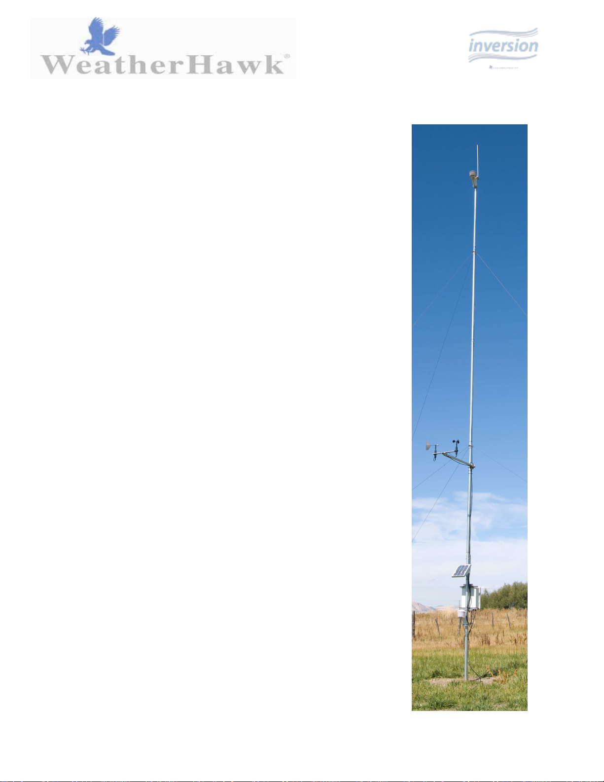
Temperature Inversion System
Site Installation Manual
Page 2

Page 3

Table of Contents
1. Overview................................................................................1
1.1. Power Sources .........................................................................................1
1.2. Site Selection............................................................................................1
1.3. Communications Considerations ..............................................................2
1.3.1 Direct Communications....................................................................................... 2
1.3.1.1 Cable Lengths..................................................................................... 2
1.3.1.2 Grounding Issues................................................................................ 2
1.3.2. Wireless Communications.................................................................................. 2
1.3.2.1. Transmission Ranges ........................................................................ 3
1.3.2.2. Line-of-Sight....................................................................................... 3
1.3.2.3. Testing Radio Transmissions............................................................. 4
2. Installation Procedures.........................................................4
2.1. Inversion System on Pre-Installed 30-foot Tower/Pole .............................4
2.1.1 Mounting Sensors and Enclosure....................................................................... 5
2.1.2 Cable Connections.............................................................................................. 6
2.1.3. Grounding the System ....................................................................................... 7
2.2. Installing CM375 Mast with the Inversion System.....................................8
2.2.1. Assembling CM375 Mast Sections .................................................................... 9
2.2.2. Mounting Top Temperature Sensor and Wind Set Sensor.............................. 14
2.2.3. Lightning Rod Assembly .................................................................................. 15
2.2.4. Guy-Anchor Kit Installation............................................................................... 16
2.2.5. Raise, Plumb Mast ........................................................................................... 19
2.2.6. Mounting Equipment to Lower Part of Mast..................................................... 20
2.2.7. Cable Connections........................................................................................... 21
2.2.8. Grounding Rod Installation............................................................................... 22
3. Maintenance.......................................................................23
Appendix A. Separately Purchased Equipment ......................26
A.1. Communications Options .......................................................................26
A.1.1 USB-AD Serial-to-USB Adapter........................................................................ 26
A.1.2. RS485-KT Communications Module Kit.......................................................... 26
A.2. Power Supply Options............................................................................27
A.2.1. SP2-KT Solar Panel Kit ................................................................................... 27
A.2.2. ACP1 AC Converter......................................................................................... 27
A.3. Instrument Mounts and Mounting Hardware...........................................27
A.3.1 Grounding Kit (pn. 21660) ................................................................................ 27
A.3.2. CM375 10-Meter Mast..................................................................................... 28
A.3.3. Heavy-Duty Duckbill Anchor Kit (pn. 25699) ................................................... 28
A.3.4. Standard Anchor Kit (pn. 19282)..................................................................... 28
A.3.5. Guy Tensioning Kit (pn. 22071)....................................................................... 29
Page 4
Site Installation Guide
The WeatherHawk Temperature Inversion System is a meteorological platform designed for detecting the presence of
a surface temperature inversion. A temperature inversion occurs when temperature increases with height within the
lowest layer of the atmosphere (troposphere). This is called an inversion because normally within the troposphere,
temperature decreases with height. Temperature inversions can effect human-environment interaction in different
ways including agriculture, air quality, prescribed burns, and many others.
This guide includes procedures for installing your WeatherHawk Inversion system on a 30 foot tower for permanent
or portable installations. For permanent installations, use the WeatherHawk CM375 Mast with the Heavy Duty
Anchor Kit ( pn. 25699), UT30 Permanent Tower, or preinstalled user-supplied tower. For temporary installations,
use the WeatherHawk CM375 mast with the Standard Anchor Kit (pn. 19282) or a user-supplied temporary mast.
Before installing your WeatherHawk Inversion system read over the sections on power sources, site selection, and
communications considerations. Equipment that is purchased separately is described in Appendix A.
1. Overview
1.1. Power Sources
WeatherHawk Inversion systems are provided with an internal sealed rechargeable lead acid battery that must be
recharged to assure continued system function. To recharge the battery, WeatherHawk offers solar panels or an
AC/DC power converter. If no power supply has been ordered, you must provide an external DC power source with
an output of 18 V @ 1.2 A.
Connecting an incompatible power source to your WeatherHawk voids your Warranty. Please
check with WeatherHawk Customer Service before connecting a third party power source.
1.2. Site Selection
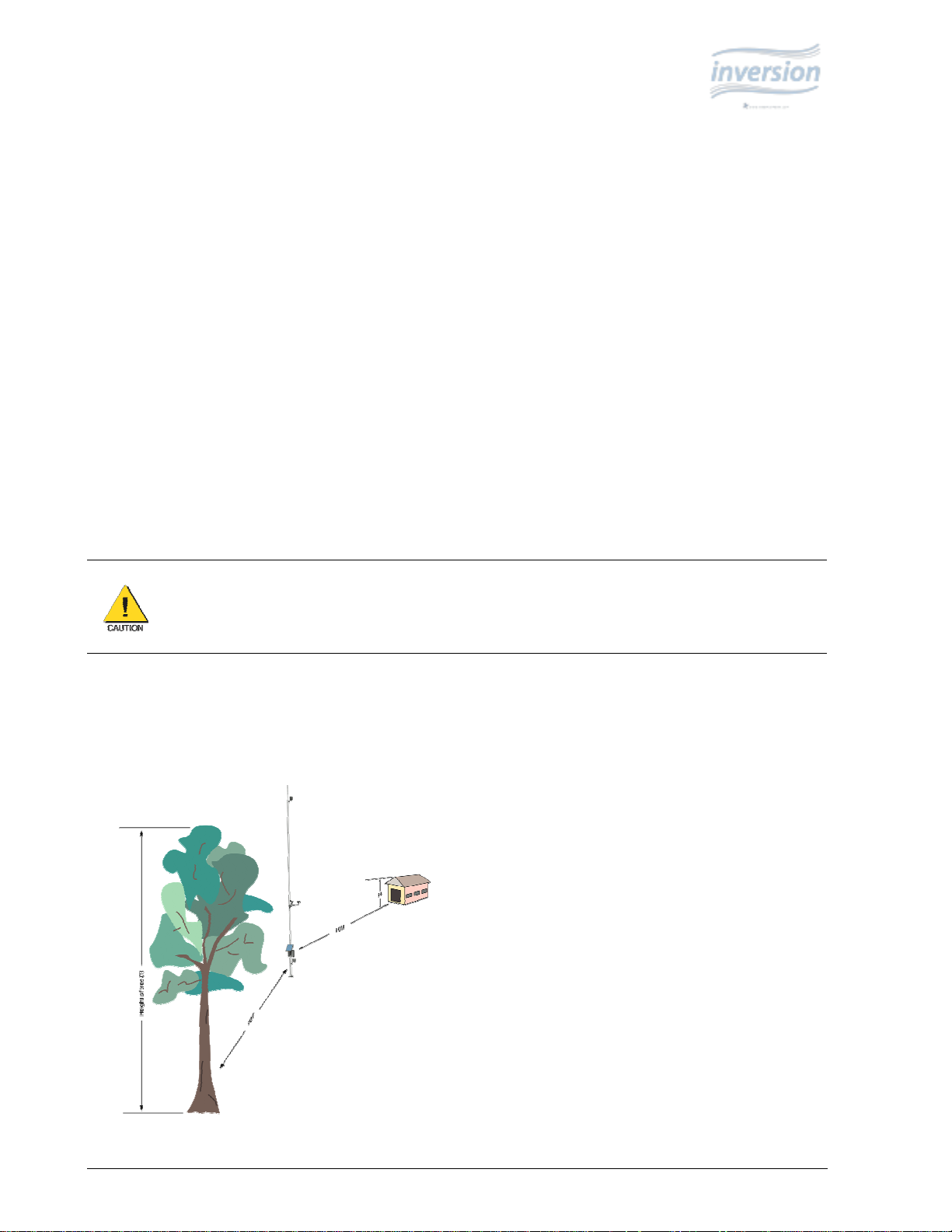
WeatherHawk Inversion systems are designed for installations on a 30-foot mast or tower. The ideal WeatherHawk
Inversion installation site is level and well away from obstructions such as buildings, trees and steep slopes. If
obstructions do exist, use the “Ten Times the Height Rule”, which is illustrated in Figure 1.
WeatherHawk ® 1
815 W. 1800 N. Logan, Utah 84321-1784, Email: service@weatherhawk.com Copyright © 2004, 2010
Toll free in USA: 866-670-5982, International: 435-750-1802, FAX: 435-750-1749 Printed November 2010
Figure 1: Ten Times the Height Rule. n example, if the height of the
tree, T, is 37 feet and the height of the shed, H, is 24 feet then the
WeatherHawk station should be placed at least 370 feet from the tree
(i.e., 10T = 10 x 37 = 370 ft) and 240 feet away from the shed (i.e.,
10H = 10 x 24 = 240 ft).
Page 5

If your WeatherHawk station will be inside a fence to discourage vandalism, the fence top
edge must be lower than the wind sensors even if the fence is chain-link. .
1.3. Communications Considerations
WeatherHawk offers a variety of communication options for use with the WeatherHawk Temperature Inversion
System. The best communication option to use is dependent on the end user’s application and location resources.
The most common options used are direct RS232 or wireless, spread spectrum radio. Other communication options
are available for the Temperature Inversion System. For information on other communications options, contact
WeatherHawk Customer Service.
1.3.1. Direct Communications
Direct communications simply use an RS232 cable connected directly to the WeatherHawk and a host computer. If
direct communications are used, an optical isolation kit is recommended to help protect the host computer in case of a
lightning strike.
1.3.1.1. Cable Lengths
The maximum length for an RS232 cable is 75 feet. For cable lengths longer than 75 feet, use an MD485-KT
Communications Module Kit and a user-supplied CAT 5 cable, or a StrikeGuard fiber optic modem kit.
1.3.1.2. Grounding Issues
The tower or mast must be properly grounded to protect the WeatherHawk Inversion system and/or any connected
Host device or computer from electrical surges caused by lightning or other environmental sources. The Grounding
Kit (pn. 21660) includes the equipment required to properly ground the system. This kit consists of a lightning rod,
lightning rod bracket, U-bolt with matching nuts, grounding rod, ground wire, ground wire clamp, and locking nut.
The Grounding Kit is included with the CM375 mast and can also be purchased separately.
1.3.2. Wireless Communications
Wireless communications use a spread spectrum radio to transmit data between the WeatherHawk Inversion System
and a host computer over short distances. In order for the wireless communications to work properly, line-of-site
between the WeatherHawk and the radio receiver attached to the host computer must be present.
To minimize the possibility of equipment damage or personal hazard, we strongly recommend a
qualified electrician install the grounding and data isolation components of a directly wired
installation.
WeatherHawk ® 2
815 W. 1800 N. Logan, Utah 84321-1784, Email: service@weatherhawk.com Copyright © 2004, 2010
Toll free in USA: 866-670-5982, International: 435-750-1802, FAX: 435-750-1749 Printed November 2010
Page 6
The ranges assume no obstructions are in the line
-of-
sight. Line
-of-
sight is defined and described below.
1.3.2.1. Transmission Ranges
Site your WeatherHawk within the spread spectrum radio transmission range. Typical line-of-sight (LOS)
transmission ranges are listed below:
• Standard WeatherHawk Antennas: up to ½ mile (0.8 km)
• Optional Higher Gain Antennas on Both the Weatherhawk Station and the Base Station: Up to 7
miles
1.3.2.2. Line-of-Sight
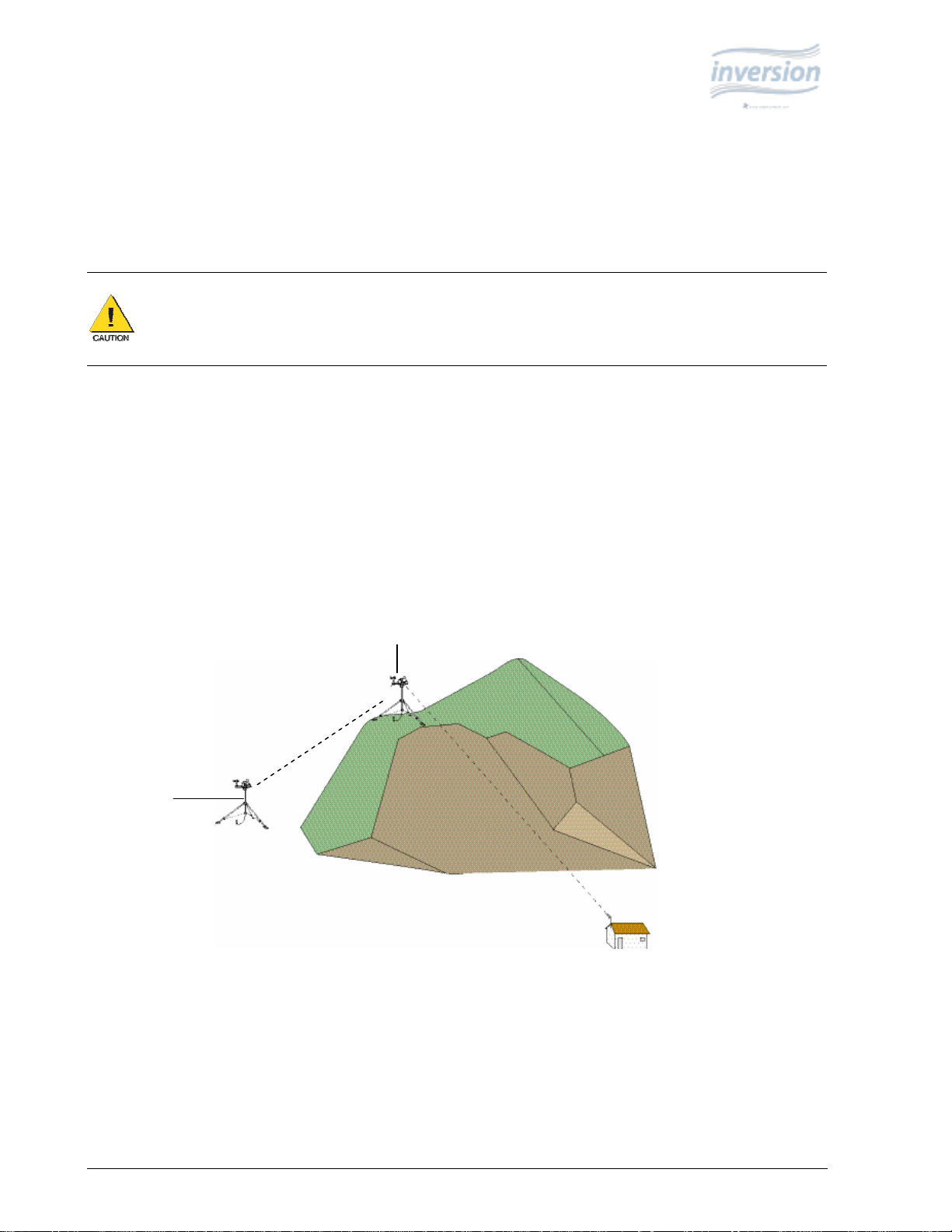
Line-of-sight is defined as a straight path between a transmitting and receiving antenna that is unobstructed by
intermediate topography or obstructions (see Figure 2). A clear line-of-sight is required to achieve the optimum
transmission range.
The affect of obstructions on the transmission range can vary. Generally, trees, foliage, metal siding, and metal
roofing absorb or reflect radio frequency—reducing the direct transmission range of a WeatherHawk wireless system.
Wood frame and brick buildings affect the radio frequency less significantly. Sometimes, radio frequencies find an
indirect path by reflecting from the weather station to the base location. However, over-the-horizon sites must use
repeaters or antennas mounted high on a tall mast to get a clear line-of-sight.
Station 2
Station 1
Figure 2: Line-of-sight examples. As the dotted line indicates, Station 1 has a clear line-of-sight with the Computer
Site. The mountain obstructs Station 2's line-of-sight and would attenuate the RF signal or prevent the
communications completely. Station 1 can be used as a repeater for Station 2.
If obstructions lie within the line-of-sight, you should test radio transmission range before permanently installing your
WeatherHawk station (see Testing Radio Transmissions below).
WeatherHawk ® 3
815 W. 1800 N. Logan, Utah 84321-1784, Email: service@weatherhawk.com Copyright © 2004, 2010
Toll free in USA: 866-670-5982, International: 435-750-1802, FAX: 435-750-1749 Printed November 2010
Page 7

1.3.2.3. Testing Radio Transmissions
Test the radio transmission of your WeatherHawk Inversion system by doing the following:
1. Connect your WeatherHawk Inversion System to the Host computer using the RS-232 cable or the RS-232
cable/USB adapter combination.
2. Initiate communications using WeatherHawk Inversion software. If the Inversion system is not properly
communicating with the computer, check the settings and connections. You can also contact WeatherHawk
Customer Service for help.
3. After establishing communications with the computer via the hard-wired connection, disconnect the cable from
the WeatherHawk and the host computer.
4. Initiate wireless communications between with the WeatherHawk and the host computer. If the Inversion system
is not properly communicating with the computer, check the settings and connections. You can also contact
WeatherHawk Customer Service for help.
5. After successfully establishing wireless communications in the office, move the WeatherHawk station to the field
site.
6. Initiate wireless communications with the WeatherHawk station using the Host computer. If the station is not
properly communicating with the computer, obstructions in the line-of-sight may be preventing communications.
If obstructions in the line of sight are preventing the WeatherHawk from communicating, try the following:
• Relocate your WeatherHawk away from obstructions.
• Remove the obstructions.
• Mount the computer base station antenna outside of the building by running the antenna cable through a
window or cable run.
• Use a higher gain antenna at the computer site.
• Install a higher gain antenna on the roof of the computer site’s building and align it above the obstructions.
If you experience problems with RF communications, you can contact WeatherHawk Customer
Service. To allow us to effectively help you, please be prepared to describe, in detail, your
installation and site conditions.
2. Installation Procedures
This document provides installation procedures for two standard configurations. Other configurations for the
WeatherHawk are possible. For questions about configurations not described in this document, contact
WeatherHawk Customer Service.
2.1. Inversion System on Pre-Installed Tower/Pole at Least
30-feet Tall
This procedure is for customers who are using a pre-existing tower or pole that is at least 30 feet tall. If the
tower/pole is not collapsible or foldable to ground level, a lift bucket will be required to mount the equipment at the
30 feet level. The user will need a cross-arm with which to mount the wind sensor on. The cross-arm should mount
perpendicular to the tower/pole, extend at least 3 feet away from the tower, and have a diameter of 1 inch. The user
will also need a grounding rod and cable with which to ground the system. A compass should be used to ensure
proper alignment of instrumentation. These items are available for purchase from WeatherHawk if needed.
WeatherHawk ® 4
815 W. 1800 N. Logan, Utah 84321-1784, Email: service@weatherhawk.com Copyright © 2004, 2010
Toll free in USA: 866-670-5982, International: 435-750-1802, FAX: 435-750-1749 Printed November 2010
Page 8
If you are installing the CM375 mast at the same time as the Inversion System, go to Section 2.2.
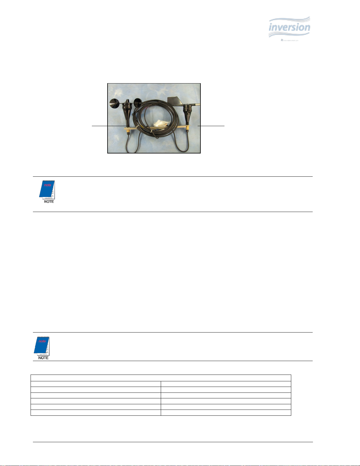
The following tables list the equipment that is included with an inversion system for mounting on a pre-existing
tower/pole. It is advisable to inventory the system for completeness before beginning installation. Power supply
options are listed in Appendix A.
Inversion System Common Components
Equipment Description Part Number Quantity
Temperature Probe, Top 21414 1
Temperature/RH Probe, Bottom 21415 1
6-Plate Gill Solar Radiation Shield 4020 2
Lead Acid Battery, 12 Volt, 2.9 AHr 18860 1
Wind Sensor Set w/Mounting Hardware 21413 1
Cable Tie, Black, UV Resistant 17592 12
Direct Connect System Specific Components
Equipment Description Part # Qty
Enclosure Assembly – 232 21379 1
RS – 232 Optical Isolator, 9 – pin 21429 1
RS – 232 Optical Isolator Power
Supply
RS – 232 Data Cable 10873 1
21435 1
Wireless System Specific Components
Equipment Description Part # Qty
Enclosure Assembly – 916 21380 1
900MHz Spread Spectrum
Radio
900MHz Dipole Antenna 15970 1
Radio Power Adapter 15966 1
18102 1
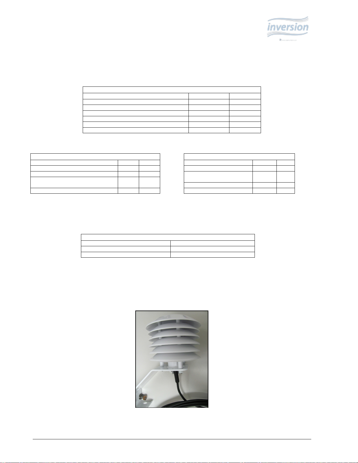
The top temperature probe and the bottom temperature/RH probe should already be mounted inside the solar radiation
shields. The following table lists the hand tools necessary to install a WeatherHawk Temperature Inversion System.
½ inch wrench Compass
#2 Phillips Screwdriver Post Level
Small Wire Cutters Tape Measure
Hand Tools List
2.1.1. Mounting Sensors and Enclosure
1. Mount the top Temperature Sensor (pn. 21414) at a height of 30 feet on the south side of the tower/pole. Place the
provided U-bolt in the side holes of the radiation shield (see Figure 5) and tighten the nuts.
Figure 5: Temperature
radiation shield
(pn 21414).
WeatherHawk ® 5
815 W. 1800 N. Logan, Utah 84321-1784, Email: service@weatherhawk.com Copyright © 2004, 2010
Toll free in USA: 866-670-5982, International: 435-750-1802, FAX: 435-750-1749 Printed November 2010
Page 9
2. Mount the wind speed and direction sensors onto the crossarm using the provided U-bolts (see Figure 6). The
cross-arm should be mounted to the tower such that the wind sensors are at a height of 11 feet, on the south side
of the tower with the direction sensor to the west and the speed sensor to the east. There is a reference mark on
the wind direction sensor that should face north when mounted correctly.
Wind Speed Sensor
Wind Direction Sensor
Figure 6: Wind speed and direction sensors.
A compass is included in the Tensioning Kit (pn. 22071) to help you properly align the sensors. The
tensioning kit is purchased separately from WeatherHawk.
3. Secure the sensor cables to the mast using UV-tolerant plastic cable ties (supplied).
4. At a height of 3 feet , use the supplied U-bolt to mount the Temperature/RH sensor (pn. 21415), on the south side
of the tower/pole . The U-bolt is placed in the side holes of the radiation shield and then the nuts tightened.
5. Open the enclosure and retrieve the mounting U-bolts from the battery mounting bracket (wrapped in bubble
wrap). At a height of 4 feet, mount the enclosure to the tower/pole so that it’s facing NORTH.
6. If applicable, mount the solar panel to the mast using the provided U-bolts. The solar panel should be mounted 1
foot above the enclosure and facing SOUTH.
2.1.2. Cable Connections
1. Connect the sensor cables to the underside of the enclosure (see Table 1).
WeatherHawk Inversion sensor cables and enclosure connectors are color coded to assist with correct
installation (see Table 1).
Table 1. Connections
Sensor/Device Color
21414 Top Temperature Sensor Blue
Lower Temperature/RH sensor Brown
Wind Direction Sensor Purple
Wind Speed Sensor Yellow
Power/Charge Red
WeatherHawk ® 6
815 W. 1800 N. Logan, Utah 84321-1784, Email: service@weatherhawk.com Copyright © 2004, 2010
Toll free in USA: 866-670-5982, International: 435-750-1802, FAX: 435-750-1749 Printed November 2010
Page 10
2. Secure the sensor cables to the mast with the provided cable ties.
3. If your system is direct communications, attach the serial cable connector to the WeatherHawk 9-pin RS232
connector.
4. If your system is wireless, attach the antenna to the enclosure connector labeled ANTENNA (antenna is taped to
the inside of enclosure).
5. Open the enclosure and install battery on battery mounting bracket using strap to secure battery to bracket.
Remove plastic protective caps from battery posts and attach battery cables making sure to connect the red cable
to the red battery post and the black cable to the black battery post.
6. Attach the AC power converter or solar panel cable to the enclosure connector labeled CHARGE (Red).
7. Open the enclosure and turn the system power switch to the ON position, making sure the green light is
illuminated.
a. If using a serial connection, ensure that the serial port on host computer is not already assigned to
an open program.
b. Connection to a computer’s USB port is possible via the USB-AD serial-to-USB converter cable.
The USB-AD (pn. 16878) can be purchased separately from WeatherHawk.
2.1.3. Grounding the System
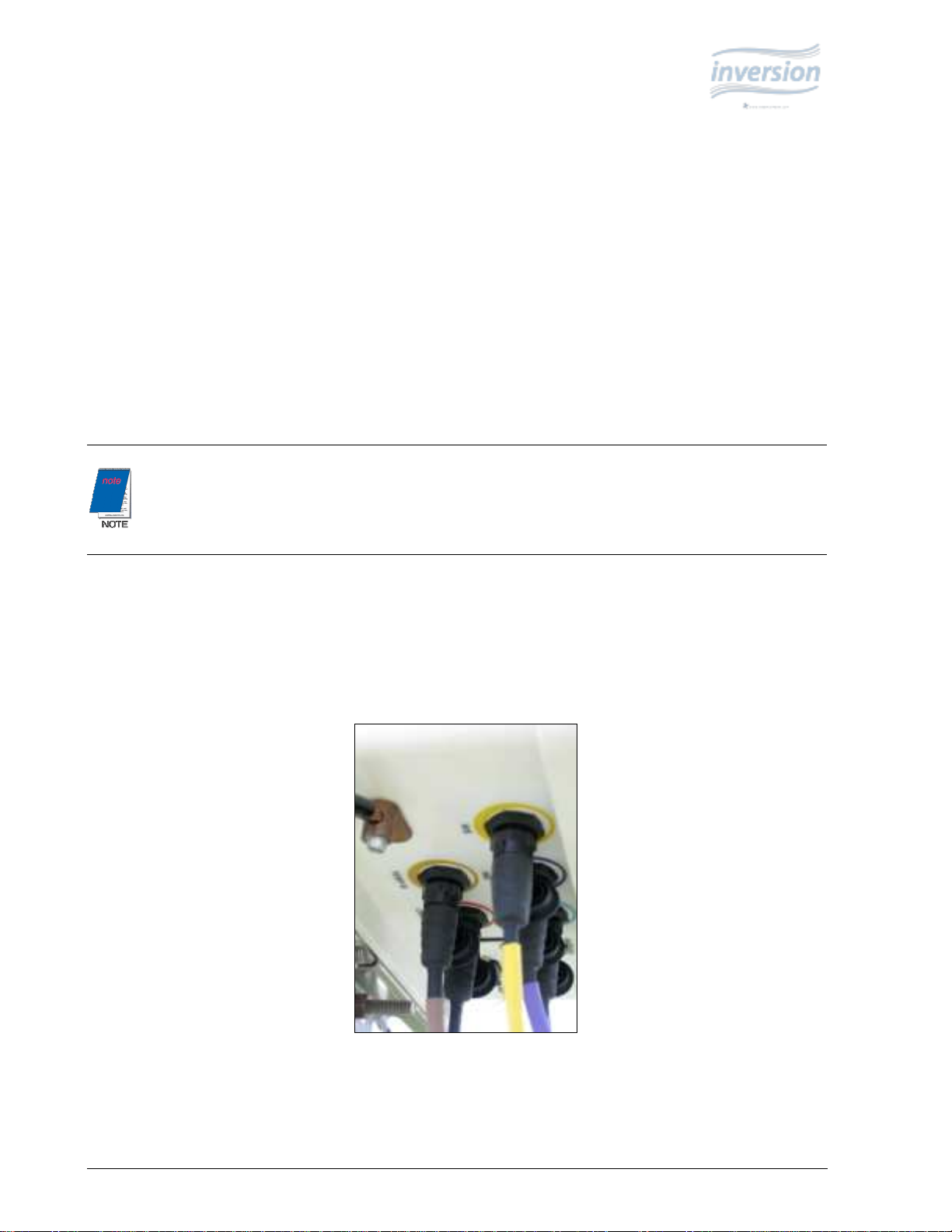
If not already present, drive ground rod into ground within 1 foot of tower and attach ground cable to rod.
1. Insert the grounding cable into the ground lug on the bottom of the system enclosure, and tighten the lug (see
Figure 8).
Figure 8: Ground Cable
connected to enclosure
ground lug (upper left).
WeatherHawk ® 7
815 W. 1800 N. Logan, Utah 84321-1784, Email: service@weatherhawk.com Copyright © 2004, 2010
Toll free in USA: 866-670-5982, International: 435-750-1802, FAX: 435-750-1749 Printed November 2010
Page 11

2.2. Installing the CM375 Mast with the Inversion System
This procedure is for customers who are installing the CM375 30-foot mast at the same time as their inversion system.
Use Procedure 1 (instead of this procedure) if your CM375 mast has already been installed. The table below is a list of
hand tools necessary for installing the CM375 mast with the inversion system.
½ inch Wrench Compass
#2 Phillips Screwdriver Rubber Mallet
Small Wire Cutters Guy-wire Tension Tool
Tape Measure (25 ft) Post Level
Hand Tool List
The compass, guy-wire tension tool, and post level are included in the Tensioning Kit which can be purchased
separately from WeatherHawk.
The following tables list the equipment that is included with the WeatherHawk Inversion System. To ensure that all
equipment is present, and inventory should be conducted before beginning installation.
Inversion System Common Components
Equipment Description Part Number Quantity
Temperature Probe, Top 21414 1
Temperature/RH Probe, Bottom 21415 1
6-Plate Gill Solar Radiation Shield 4020 2
Lead Acid Battery, 12 Volt, 2.9 AHr 18860 1
Wind Sensor Set w/Mounting Hardware 21413 1
Cable Tie, Black, UV Resistant 17592 12
Direct Connect System Specific Components
Equipment Description Part # Qty
Enclosure Assembly – 232 21379 1
RS – 232 Optical Isolator, 9 – pin 21429 1
RS – 232 Optical Isolator
Power Supply
RS – 232 Data Cable 10873 1
21435 1
Description Qty Description Qty
Baseplate Assembly 1 Grounding cable w/hardware 1
Baseplate Stakes 4 Duckbilled anchor driver 1
Mast Extensions 5 Duckbilled anchor w/cables 3
Mast Extension Couplers 3 Guy wire set, short 1
Mast Hardware 8 sets Guy wire set, long 1
Lightning Rod with bracket 1 Turnbuckles 6
Cross-arm w/mounting hardware 1 Ground Rod 1
CM375 Mast Assembly
The top temperature probe and bottom temperature/RH probe should already be housed in the 6-plate solar radiation
shield. The mast extension couplers should already be installed on the proper mast extensions.
Wireless System Specific Components
Equipment Description Part # Qty
Enclosure Assembly – 916 21380 1
900MHz Spread Spectrum
Radio
900MHz Dipole Antenna 15970 1
Radio Power Adapter 15966 1
18102 1
WeatherHawk ® 8
815 W. 1800 N. Logan, Utah 84321-1784, Email: service@weatherhawk.com Copyright © 2004, 2010
Toll free in USA: 866-670-5982, International: 435-750-1802, FAX: 435-750-1749 Printed November 2010
Page 12

2.2.1. Assembling CM375 Mast Sections
1. Remove mast sections and other bundled hardware from the tote (see Figure 9).
The crossarm-to-pole
mounting kit (pn. 21669)
contains the lightning rod,
copper grounding rod, and
duckbill anchor drive rod.
2. Place Mast Section 1 at the site location with the base oriented as shown in Figure 11, and with the mast aligned
NORTH/SOUTH.
Sections are numbered for sequential assembly (see Figure 10).
Base
Figure 11: Mast Section 1
Oriented on Base
Figure 9: CM375 Tote (pn. 21720)
Figure 10: Mast Sections and Base
WeatherHawk ® 9
815 W. 1800 N. Logan, Utah 84321-1784, Email: service@weatherhawk.com Copyright © 2004, 2010
Toll free in USA: 866-670-5982, International: 435-750-1802, FAX: 435-750-1749 Printed November 2010
Page 13

3. Use the provided spikes (three each) to secure the base to the ground (see Figure 12).
A compass is included in the Tensioning Kit (pn. 22071) to help you properly align the sensors. The
tensioning kit is purchased separately from WeatherHawk.
Figure 12: Spikes Installation
4. Insert the coupler from Mast Section 2 into the top of Mast Section 1 (see Figure 13).
Figure 13: Coupler Installed in Top of Mast Section 1
WeatherHawk ® 10
815 W. 1800 N. Logan, Utah 84321-1784, Email: service@weatherhawk.com Copyright © 2004, 2010
Toll free in USA: 866-670-5982, International: 435-750-1802, FAX: 435-750-1749 Printed November 2010
Page 14

5. Secure the coupler joint using two flat washers, two lock washers and two bolts from the hardware bag (see
Figure 14)
Figure 14: Bag
Containing Hardware
6. Place Mast Section 3 near the top of Mast Section 2 (see Figure 15).
The BLACK tape around Mast Section 2 is a reference indicator (11 foot level) for wind set sensor mounts.
7. Remove the collars from Mast Section 3 and place them next to the mounting holes in Mast Section 2 (see
Figures 15 and 16).
Figure 15: Mast Section 2 and Mast Section 3
Figure 16: Guy Ring, Mast Section 2, and Mast Section 3
WeatherHawk ® 11
815 W. 1800 N. Logan, Utah 84321-1784, Email: service@weatherhawk.com Copyright © 2004, 2010
Toll free in USA: 866-670-5982, International: 435-750-1802, FAX: 435-750-1749 Printed November 2010
Page 15

8. Remove the guy ring from the bottom guy kit (pn. 21663); see Figures 16 and 17.
9. Insert the ball end of each guy cable into its slot in the guy ring, and place the coupler of Mast Section 3 into the
guy ring (see Figure 18).
10. Slide the coupler into Mast Section 2, and assemble the collars as shown in Figure 19.
Only one of three cables is shown.
Figure 19: Mast Section 3 and Guy Ring/Collar Assembly
Figure 17: Bottom Guy Kit (pn. 21663)
Figure 18: Guy Cables Inserted into Guy Ring
WeatherHawk ® 12
815 W. 1800 N. Logan, Utah 84321-1784, Email: service@weatherhawk.com Copyright © 2004, 2010
Toll free in USA: 866-670-5982, International: 435-750-1802, FAX: 435-750-1749 Printed November 2010
Page 16

11. Slide the coupler end of Mast Section 4 into the top of Mast Section 3, and fasten with the remaining components
from hardware bag (see Figure 20).
Figure 20: Mast Section 4 Ready to Be Installed in Mast Section 3
12. Remove the collars from Mast Section 5 (see Figure 21).
Figure 21: Mast Section 5
13. Slide mast into Section 4 and assemble the collars as shown in Figure 22.
Figure 22: Mast Section 5 Installed in Mast Section 4
WeatherHawk ® 13
815 W. 1800 N. Logan, Utah 84321-1784, Email: service@weatherhawk.com Copyright © 2004, 2010
Toll free in USA: 866-670-5982, International: 435-750-1802, FAX: 435-750-1749 Printed November 2010
Page 17

14. Remove the guy collar from the top guy kit (pn. 21661); see Figure 23.
15. Insert the ball ends of the guy cable into the guy ring, and then slide the ring down the mast to the collar (see
Figure 24).
Figure 23: 21661 Guy Kit
Figure 24: Mast Section 5 and Guy Ring/Collar Assembly
2.2.2. Mounting Top Temperature Sensor and Wind Set Sensor
1. Mount the top Temperature Sensor (pn. 21414) 10 inches from the top of Mast Section 5. Place the provided Ubolt in the side holes of the radiation shield and tighten the nuts.
WeatherHawk ® 14
815 W. 1800 N. Logan, Utah 84321-1784, Email: service@weatherhawk.com Copyright © 2004, 2010
Toll free in USA: 866-670-5982, International: 435-750-1802, FAX: 435-750-1749 Printed November 2010
Page 18

2. Mount the wind speed and direction sensors onto the crossarm using the provided U-bolt (see Figure 25).
3. Use the supplied U-bolts and mounting hardware to attach the crossarm to the mast. The cross-arm should be
mounted such that the cross-arm is perpendicular to the mast at a height of 11 feet on the mast. The wind sensors
should be oriented such that they are on the south side of the mast when upright, and the directions sensor
reference mark is facing due north. Black masking tape on Mast Section 2 indicate the proper location for the
crossarm.
Figure 25: Wind speed and direction sensors.
Be sure to run guy wires under the crossarm.
4. Secure the cables to the mast using UV-tolerant plastic tie wraps (supplied).
2.2.3. Lightning Rod Assembly
1. Retrieve the lightning rod clamp, lightning rod, U-bolt, and nuts from the Grounding Kit (pn. 21660);
see Figure 26.
Figure 26: Lightning Rod Assembly
WeatherHawk ® 15
815 W. 1800 N. Logan, Utah 84321-1784, Email: service@weatherhawk.com Copyright © 2004, 2010
Toll free in USA: 866-670-5982, International: 435-750-1802, FAX: 435-750-1749 Printed November 2010
Page 19

2. Mount the lightning rod clamp onto the top of Mast Section 5 using the U-bolt and nuts (see Figure 27).
3. Insert the lightning rod into the clamp and tighten the screws (see Figure 27).
Figure27: Installed Lightning Rod
2.2.4. Guy-Anchor Kit Installation
A choice of duckbill anchor kits is offered for the CM375. The Duckbill Standard Anchor Kit (pn. 19282) is for
standard soils, and the Duckbill Heavy Duty Anchor Kit (pn. 25699) is for aggressive soils. Aggressive soils have:
• Resistivity of less than 3000 ohm-cm
• pH of less than 5
• Chloride of greater than 1000 ppm
• Sulfate of greater than 500 ppm
• Poor aeration
Both anchor kits have one drive rod. The Standard Duckbill Anchor Kit has three duckbill anchors with a cable
attached to each of them. At the end of the cable is a loop for connecting the guy wires. The Heavy-Duty Duckbill
Anchor Kit has a threaded rod attached to each of the three duckbill anchors instead of the cable. At the end of the
threaded rod is a metal ring for connecting the guy wires.
1. For the SOUTH anchor, place the tape measure in the base slot centering the tape in the notch on the edge of the
base. Locate a point 20 feet from the mast base (see Figure 28).
Figure 28: Tape Measure in Slot for South Anchor
WeatherHawk ® 16
815 W. 1800 N. Logan, Utah 84321-1784, Email: service@weatherhawk.com Copyright © 2004, 2010
Toll free in USA: 866-670-5982, International: 435-750-1802, FAX: 435-750-1749 Printed November 2010
Page 20

NE
Drive Bar
2. At 20 feet, install the duckbill anchor with the supplied drive rod. The anchor needs to be driven into the ground
at a 45° angle (see Figure 29). Drive the anchor into the soil until the loop or metal ring is approximately 4
inches above the ground.
3. With a rod through the loop or metal ring, pull up on the cable or threaded rod until the anchor rotates and locks
(see Figure 30).
Duckbill Anchor
o
60
UTDUK
Figure 29: Anchor Driven into Ground at 45° Angle.
(towers)
Figure 30: Locking Anchor
4. Fill-in the hole around the cable or threaded rod with loose dirt and tap firm.
5. Repeat process for the northeast (see Figure 31) and northwest anchors.
Figure 31: Tape Measure in slot
for North East Anchor
WeatherHawk ® 17
815 W. 1800 N. Logan, Utah 84321-1784, Email: service@weatherhawk.com Copyright © 2004, 2010
Toll free in USA: 866-670-5982, International: 435-750-1802, FAX: 435-750-1749 Printed November 2010
Page 21

6. Attach guy wires to anchors by first opening the turnbuckle to the widest setting. Attach turnbuckle to wedge
end of the guy cable, and then attach the other end of the turnbuckle to an anchor (see Figure 32).
Guy Cable Wedge
7. If using a rope ratchet to assist assembly, set to 7 feet and attach to tension clamp on cable and to anchor end. Do
this for both NE and NW anchors and top bottom guy cables.
8. Course adjustments to cable length are made by loosening screw clamp and then releasing wedge with a flatbladed screwdriver. This allows the cable to be adjusted through the wedge clamp (see Figure 33).
Do not connect the SOUTH cables at this time.
Figure 32: Turnbuckle Fastened to Guy Cable and Anchor.
Open turnbuckle to widest setting Anchor
Retighten screw when adjustment is complete.
Figure 33: Adjusting Cable through Wedge Clamp
WeatherHawk ® 18
815 W. 1800 N. Logan, Utah 84321-1784, Email: service@weatherhawk.com Copyright © 2004, 2010
Toll free in USA: 866-670-5982, International: 435-750-1802, FAX: 435-750-1749 Printed November 2010
Page 22

2.2.5. Raise and Plumb the Mast
1. With NW and NE cables attached to anchors, have one person lift the mast, while another person pulls on the
SOUTH cables to bring the mast to an upright position (see Figure 34). If using rope ratchets, adjust them to
allow further steps.
2. Attach the SOUTH cables to the anchor. While one person holds onto the mast and uses the post level, the
second person can adjust each of the bottom guy cable wedge clamps—maintaining level in all directions (see
Figure 35). The rope ratchet can be used to temporarily remove the load from the wedge assembly during wedge
adjustments.
Figure 35: Pole
Level Ensures
Vertical Mast.
3. Repeat the process with the top guy cables to establish a straight mast.
4. Apply fine tensioning adjustments using the turnbuckles (see Figure 36).
Figure 36: Adjusting
Turnbuckles.
Figure 34: Raising the Mast.
WeatherHawk ® 19
815 W. 1800 N. Logan, Utah 84321-1784, Email: service@weatherhawk.com Copyright © 2004, 2010
Toll free in USA: 866-670-5982, International: 435-750-1802, FAX: 435-750-1749 Printed November 2010
Page 23

5. Adjust each cable turnbuckle to maintain plumb and increase cable tension. A deflection of 3 inches (when using
a 4.4 pound (2N) perpendicular force 68 inches from the duckbill anchor loop) equates to 100 pounds of tension
in the cables (see Figure 37).
Figure 37: Guy Cables with 100 lbs of Tension.
6. After tensioning the top guy cables, recheck the bottom guy cables. Adjust as necessary.
2.2.6. Mounting Equipment to Lower Part of Mast
1. Use the U-bolt to mount the Temperature/RH sensor (pn. 21415) onto Mast Section 1. Mount the sensor so that
it’s facing SOUTH at a height of 3 feet (see Figure 38).
2. Open the system enclosure and remove the mounting U-bolts (wrapped in bubble wrap) from the battery
mounting bracket. Mount the enclosure to Mast Section 1, so that it’s facing NORTH at a height of 4 feet
(see Figure 38).
Figure 38: Temperature
and RH sensor and
enclosure mounted to
CM375 Mast.
WeatherHawk ® 20
815 W. 1800 N. Logan, Utah 84321-1784, Email: service@weatherhawk.com Copyright © 2004, 2010
Toll free in USA: 866-670-5982, International: 435-750-1802, FAX: 435-750-1749 Printed November 2010
Page 24

3. Open the enclosure and install battery on battery mounting bracket using strap to secure battery to bracket.
Remove plastic protective caps from battery posts and attach battery cables making sure to connect the red cable
to the red battery post and the black cable to the black battery post.
4. If applicable, mount the solar panel to Mast Section 1 using the provided U-bolts. The solar panel should be
mounted 1 foot above the enclosure and facing SOUTH.
2.2.7. Cable Connections
1. Connect the sensor cables to the underside of the enclosure (see Table 2).
2. Secure the cables to Mast Section 1 with the provided cable ties.
3. If your system is direct connect, attach the serial cable connector to the WeatherHawk 9-pin RS232 connector.
4. If your system is wireless, attach the antenna to the enclosure connector labeled ANTENNA.
5. Attach the AC Power Converter or solar panel cable to the enclosure connector labeled CHARGE (Red).
6. Open the enclosure and turn the system power switch to the ON position, making sure the green light is
illuminated.
WeatherHawk Inversion sensor cables and enclosure connectors are color coded to assist with correct
installation (see Table 2).
Sensor/Device Color
Table 2. Connections
21414 Top Temperature Sensor Blue
Lower Temperature/RH sensor Brown
Wind Direction Sensor Purple
Wind Speed Sensor Yellow
Power/Charge Red
a. If using a serial connection, ensure that the serial port is not already assigned to an open
program.
b. Connection to a computer’s USB port is possible via the USB-AD serial-to-USB converter cable.
The USB-AD (pn. 16878) can be purchased separately from WeatherHawk.
WeatherHawk ® 21
815 W. 1800 N. Logan, Utah 84321-1784, Email: service@weatherhawk.com Copyright © 2004, 2010
Toll free in USA: 866-670-5982, International: 435-750-1802, FAX: 435-750-1749 Printed November 2010
Page 25

2.2.8. Grounding Rod Installation
1. Retrieve the grounding rod, ground wire, ground wire clamp, and locking nut from the grounding kit.
2. Within 1 foot of the base, drive the copper grounding rod into the ground (see Figure 39).
3. Fasten the grounding cable to the grounding rod using with the locking nut (see Figure 39).
4. Insert the grounding cable to the ground lug on the underside of the enclosure, and tighten the lug
Leave approximately 5 inches of the rod above the ground.
Figure 39: Grounding Rod Driven into Ground
with Grounding Cable Secured
(see Figure 40).
Figure 40: Grounding
cable fastened to the
ground lug (top left).
WeatherHawk ® 22
815 W. 1800 N. Logan, Utah 84321-1784, Email: service@weatherhawk.com Copyright © 2004, 2010
Toll free in USA: 866-670-5982, International: 435-750-1802, FAX: 435-750-1749 Printed November 2010
Page 26

3. Maintenance
In order to ensure continued optimal operation, routine maintenance should be performed by the user on the
WeatherHawk Inveriosn System.
The following tasks should be performed on a monthly basis for permanently installed stations.
1. Inspect the mast base
• Check base for damage, cracks, corrosion, etc.
o If the base is damaged in any way, repair or replace the base immediately
• Ensure base is securely attached to ground
o The stakes holding the base to the ground may become loose for a number of reasons including:
freezing and thawing of the ground, heavy rains, strong winds, etc. If the base is not securely
attached to the ground, secure it immediately
2. Inspect mast assembly
• Check mast assembly for damage, corrosion, etc.
• Ensure mast is plumb
o Use a post level to ensure that the mast is plumb
• Check security/tightness of mast section couplers
o Check each individual bolt holding mast sections together for tightness and tighten all loose bolts
3. Inspect guy wires
• Ensure anchors are secure
o Tighten any loose components
• Inspect guy wires, turnbuckles, and wedge ends for damage, corrosion, etc.
o Repair or replace any damaged components
• Check tension of guy wires
o Tighten/loosen any guy wires not within specifications
4. Inspect vegetation around station
• Ensure vegetation is not growing into system sensors or enclosure
o Cut vegetation as necessary
The following tasks should be performed on a quarterly basis for permanently installed stations
1. Inspect lightning rod
• Check lightning rod for damage and corrosion
o Replace any damaged components
• Ensure lightning rod is securely fastened to top of mast
o Tighten any loose connections
WeatherHawk ® 23
815 W. 1800 N. Logan, Utah 84321-1784, Email: service@weatherhawk.com Copyright © 2004, 2010
Toll free in USA: 866-670-5982, International: 435-750-1802, FAX: 435-750-1749 Printed November 2010
Page 27

2. Inspect top temperature sensor and radiation shield
• Remove temperature sensor from radiation shield and inspect sensor for visible damage
o Replace any damaged sensors
• Inspect radiation shield for damage, debris, insects, and spider nests
o Replace any damaged shields. Remove any foreign objects from shield and clean shield
• Once radiation shield is clean, replace top temperature sensor
• Ensure radiation shield is securely mounted to mast
3. Inspect wind sensors
• Check wind speed sensor for damage
• Check wind direction sensor for damage
• Ensure sensors are securely mounted to crossarm
• Ensure crossarm is securely mounted to mast
• Ensure crossarm is level
4. Inspect bottom temperature/RH sensor and radiation shield
• Remove temperature/RH sensor from radiation shield and inspect sensor for visible damage
• Inspect radiation shield for damage, debris, insects, and spider nests
• Once radiation shield is clean, replace temperature/RH sensor
• Ensure radiation shield is securely mounted to mast
Do not spray insect/spider killer inside radiation shield while temperature sensor is housed inside
shield. Contact with these chemicals could damage temperature sensor.
o Check wind speed sensor for smooth turning operation
o Listen for any grinding noise while speed sensor is turning
o Check wind direction sensor for 360° of smooth operation
o Ensure reference mark is facing north
o Replace any damaged sensors
o Replace any damaged shields. Remove any foreign objects from shield and clean shield
Do not spray insect/spider killer inside radiation shield while temperature/RH sensor is housed inside
shield. Contact with these chemicals could damage temperature/RH sensor.
WeatherHawk ® 24
815 W. 1800 N. Logan, Utah 84321-1784, Email: service@weatherhawk.com Copyright © 2004, 2010
Toll free in USA: 866-670-5982, International: 435-750-1802, FAX: 435-750-1749 Printed November 2010
Page 28

5. Inspect system enclosure
• Check outside of system enclosure for damage and corrosion
o Clean outside of enclosure
• Open system enclosure and check for insects and spiders
o Remove any insects or spiders
• Visually inspect wires/cables inside enclosure for frays and breaks
• Ensure battery is secured to mounting bracket with strap
o Tighten battery strap if loose
• Ensure enclosure is securely mounted to mast
o Tighten any loose nuts/bolts
6. Inspect solar panel (if equipped)
• Inspect solar panel for damage, corrosion, and cleanliness
7. Inspect all sensor, power, and communication cables
• Inspect all system cables for breaks and frays
• Ensure all cables are secured to mast using cable ties
For systems that are used for temporary installations, all maintenance procedures should be performed between
deployments or according to the above schedule if deployment time is greater than one month.
Do not spray insect/spider killer inside enclosure. Contact with these chemicals will damage
electronic components inside system enclosure.
o Replace any damaged panels
o Clean panels if necessary
o Repair or replace any damaged cables
o Secure any loose cables to mast using cable ties
WeatherHawk ® 25
815 W. 1800 N. Logan, Utah 84321-1784, Email: service@weatherhawk.com Copyright © 2004, 2010
Toll free in USA: 866-670-5982, International: 435-750-1802, FAX: 435-750-1749 Printed November 2010
Page 29

Appendix A. Separately Purchased Equipment
The following equipment can be used with the WeatherHawk Inversion System, but is purchased separately. This
equipment can be ordered on-line at www.weatherhawk.com. Contact WeatherHawk Customer Service for questions
concerning the equipment.
A.1. Communications Options
A.1.1 USB-AD Serial-to-USB Adapter (pn. 16878)
The USB-AD Serial-to-USB Adapter allows the WeatherHawk station to be connected to the USB port on a
computer. It is required for newer laptops or PCs that do not have a 9-pin RS-232 port. The USB-AD supports data
rates up to 230 kbps.
The USB-AD includes:
• Universal Serial Bus (USB) Converter with a 1 m cable
•
Driver Software from the manufacturer (FTDI Chip): The driver software runs on Windows
98/98SE/ME/2000/XP and Linux operating systems. The WeatherHawk Inversion XP/X software CD
includes this software. It is also available from: www.ftdichip.com
A.1.2. RS485-KT Communications Module Kit (pn. 16685-5)
The RS485-KT is a wired communication option that allows the distance between the WeatherHawk Inversion 232
weather station and a host computer (PC) to be up to 4,000 feet (1300 m). A user-supplied CAT5 cable is required to
connect the WeatherHawk to the host computer. Each end of the CAT5 cable must terminate in RJ-11 connectors.
The RS485-KT includes:
•
•
• RS485 interface module for the WeatherHawk weather station
This product is commercially produced and may not always be available in this specific configuration.
WeatherHawk may substitute a part of equal or greater value if this device is discontinued by the
manufacturer.
Opto-isolated RS485 interface module for the Host PC
Power supply for the RS485 module located at the Host PC
The RS485 module for the WeatherHawk is not weatherproof and must be housed in a non-condensing
environment within 50 feet of the WeatherHawk station, or in a weatherproof enclosure at the
WeatherHawk station.
WeatherHawk ® 26
815 W. 1800 N. Logan, Utah 84321-1784, Email: service@weatherhawk.com Copyright © 2004, 2010
Toll free in USA: 866-670-5982, International: 435-750-1802, FAX: 435-750-1749 Printed November 2010
Page 30

A.2. Power Supply Options
A.2.1. SP2-KT Solar Panel Kit (pn. 16851)
The SP2-KT is a solar panel kit for recharging the internal battery. It has a 72 inch2 surface area and produces 5 W of
power at a peak of 17.1 V. The SP2-KT includes:
•
5 W solar panel
•
Mounting hardware
A.2.2. ACP1 AC Converter (pn. 18863)
The ACP1 recharges the WeatherHawk battery by converting 110-220 VAC, 50/60 Hz power to 18 VDC. It must be
housed in a non-condensing environment or a weatherproof enclosure. The ACP1 includes:
• UL-approved, AC/DC converter with US Standard plug prongs 20 feet (6.2 m)
•
UV resistant waterproof cable with an environmental connector for connecting to the WeatherHawk station.
A.3. Instrument Mounts and Mounting Hardware
A.3.1. Grounding Kit (pn. 21660)
The Grounding Kit provides the equipment required to properly ground the system. It is included with the CM375
mast, but can also be purchased separately for preinstalled towers or masts. This kit consists of:
• Lightning rod
• Lightning rod bracket
• U-bolt with matching nuts
• Copper grounding rod
• Ground wire
• Ground wire clamp
• Locking nut
WeatherHawk ® 27
815 W. 1800 N. Logan, Utah 84321-1784, Email: service@weatherhawk.com Copyright © 2004, 2010
Toll free in USA: 866-670-5982, International: 435-750-1802, FAX: 435-750-1749 Printed November 2010
Page 31

A.3.2. CM375 10-Meter Mast (pn. 21722)
The CM375 10-meter Mast can be used for either permanent or temporary installations. It comes with five 6-foot
galvanized pipes, a stainless-steel base, guy cables, a 1 m crossarm, and a mounting bracket. A duck-bill anchor kit
(required) and the guy-wire tensioning kit (recommended) are ordered separately; see below. An 80-inch-long bag is
included with the CM375; all of the CM375's components fit inside the bag allowing the CM375 to be carried from
site to site.
A.3.3. Heavy-Duty Duckbill Anchor Kit (pn. 25699)
The Heavy-Duty Duckbill Anchor Kit is one of the two kits offered by WeatherHawk; an anchor kit is required when
using the CM375. The heavy-duty anchor kit is used for permanent installations and is also recommended for areas
with aggressive soils. It consists of:
• Three duckbill anchors
• Three threaded rods (attached to each duckbill anchor)
• One driver rod (used to drive the duckbill anchors into the soil)
A.3.4. Standard Duckbill Anchor Kit (pn. 19282)
The Standard Duckbill Anchor Kit is one of the two kits offered by WeatherHawk; an anchor kit is required when
using the CM375. The standard anchor kit is used for temporary installations located in areas with standard soils. It
consists of:
• Three duckbill anchors
• Three cables (attached to each duckbill anchor)
• One driver rod (used to drive the duckbill anchors into the soil)
Anchor Cable
Figure 41: The drive rod (right) is included
with both the standard and heavy duty
anchor kits. A duckbill anchor and anchor
cable from the Standard Anchor Kit is
shown at left. The heavy duty anchor kit
includes a threaded rod instead of the cable.
Anchor
WeatherHawk ® 28
815 W. 1800 N. Logan, Utah 84321-1784, Email: service@weatherhawk.com Copyright © 2004, 2010
Toll free in USA: 866-670-5982, International: 435-750-1802, FAX: 435-750-1749 Printed November 2010
Page 32

A.3.5. Guy Tensioning Kit (pn. 22071)
The Guy Tensioning Kit provides equipment that helps you install the WeatherHawk to the correct three-axis vertical
orientation and to align the station to the magnetic North. Using this kit to properly orient the weather station helps
assure accurate measurements. The tension Kit consists of:
• One TP1-TK Tripod Installation Kit (includes multi-axis bubble level, compass, and rubber band for attaching
the bubble level to the mast)
• Three Ratchet Tie Downs
• One Guy Cable Tensiometer
WeatherHawk ® 29
815 W. 1800 N. Logan, Utah 84321-1784, Email: service@weatherhawk.com Copyright © 2004, 2010
Toll free in USA: 866-670-5982, International: 435-750-1802, FAX: 435-750-1749 Printed November 2010
 Loading...