

Page 1
TM
WeatherHawk
Quick Start Guide
Signature Series Model 232/916/922/240
Read Me First
Computer Requirements
• Available Serial Port or USB Port (Serial-to-USB Converter
Cable required)
WeatherHawk Setup Procedure
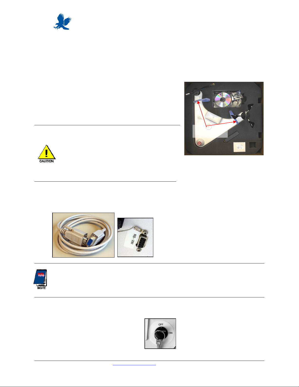
1. Remove the top foam packing from the WeatherHawk box and
verify you have all ordered equipment; then unpack equipment.
a. Use the lift straps to remove the WeatherHawk
station, since removing the station by lifting on the
sensors may damage the sensors (see Figure 1).
b. Avoid resting the WeatherHawk on the wind speed
and wind direction sensors.
c. Report missing or damaged equipment to
WeatherHawk Customer Service before installing
your system.
2. Install your application software on your computer.
Lift Straps
Figure 1: Box of standard and
wireless equipment. The lift straps
allow easy removal of the
WeatherHawk from the box.
3. Connect the serial cable male connector to the WeatherHawk RS-232 port and the serial cable female
connector to a computer serial port (Figure 2).
Figure 2: Serial cable (left) and the
WeatherHawk serial port in which the serial
cable male connector connects. A dust cover
must be removed from the WeatherHawk
RS-232 port before connecting the cable.
a. If you are using a serial connection, ensure the serial port is not already assigned to an open program.
b. If you’re connecting the cable to a USB port, a serial-to-USB converter cable is required and
optionally available from WeatherHawk (P/N 16878, USB-AD).
4. Turn the key to the on position (Figure 3), and observe a red flashing light through the small rectangular
Scan/Receive window on the underside of the WeatherHawk.
Figure 3: Keyed power switch
is located on the bottom of the
WeatherHawk station.
WeatherHawk™
815 W. 1800 N. Logan Utah 84321-1784, Email: service@weatherhawk.com Copyright © 2004
Toll free in USA: 866-670-5982, International: 435-750-1802, FAX: 435-750-1749 WeatherHawk
Printed October 2004
Page 2
5. Start application software and monitor the sensor displays. Within a couple of minutes, numerical values
should appear confirming that the WeatherHawk is functioning. The lights labeled Scan/Receive on the underside
of the station should also blink every ten seconds.
If the WeatherHawk does not function properly , cont act WeatherHawk Customer Service to solve the
problem before continuing to the next steps.
6. Using your PC and weather station software, enter the setup parameters for the station. If you are using
Virtual Weather Station software, see the section in this document labeled “Station Setup using Virtual
Weather Station Software”. If you are using the WeatherHawk XP/X software, please refer to the software
manual in the WeatherHawk folder that was created on your computer when the software was installed.
7. Disconnect the serial cable from the WeatherHawk and place the dust cover back on the serial port.
8. If your WeatherHawk is wireless (Model 916/922/240), setup the radio (see “Radio Setup” section below).
9. Install the WeatherHawk weather station at the site. Refer to the Installation Guide provided on the CD
shipped with your station for siting information and installation procedures.
Station Setup Using Virtual Weather Station Software
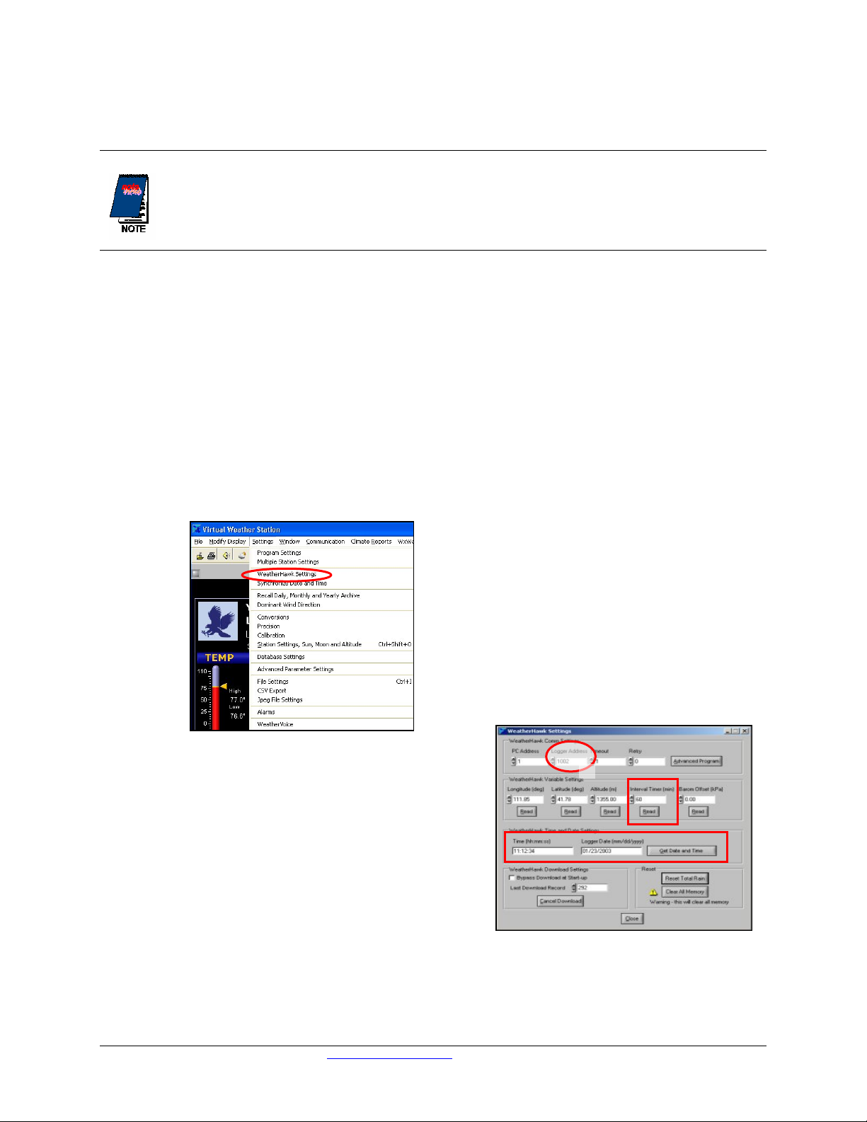
1. Click on the Settings menu and choose WeatherHawk Settings from the drop down menu (Figure 4).
2. If your WeatherHawk is wireless, change the Logger
Address to your WeatherHawk station’s serial number
(1 of Figure 5). The serial number of your WeatherHawk
is located on the underside of the station.
3. Enter the interval timer (2 of Figure 5). This value
determines how often the WeatherHawk stores the
measurements. The default is 60 minutes.
4. Click on Get Date and Time to see the date and time
stored in the WeatherHawk station (3 of Figure 5). If
the WeatherHawk’s date or time is incorrect, click on
Synchronize to Computer Time Now to set the
WeatherHawk’s date and time to the computer’s date
and time (3 of Figure 5).
Figure 4: The settings menu of Virtual
Weather Station Software. Select
WeatherHawk Settings (circled in red).
Figure 5: The Settings Screen of
Virtual Weather Station Software.
WeatherHawk™
815 W. 1800 N. Logan Utah 84321-1784, Email: service@weatherhawk.com Copyright © 2004
Toll free in USA: 866-670-5982, International: 435-750-1802, FAX: 435-750-1749 WeatherHawk
Printed October 2004
Page 3

5. Enter the Longitude, Latitude, and Altitude
(1 of Figure 6).
Longitude, Latitude, and Altitude can be
determined with a GPS Receiver, a Good
Topographical Map, or found at:
(Figure 7).
http://weather.noaa.gov/weather/ccus.html
The latitude and longitude must be entered as
decimal numbers. To convert the values to
decimal, ignore the seconds, divide the minutes by
60, then add that value to the degrees.
Example:
Latitude in Figure 6 is 41 degrees, 46 minutes,
58 seconds.
Decimal value = 41 + (46/60) = 41.78
Figure 6: The Settings Screen of Virtual
Weather Station Software. Circled are the
settings for the longitude, latitude, altitude,
and barometric pressure offset.
6. Enter the Barometric Pressure Offset (2 of Figure 6). To calculate, use the following equation:
Barometric Pressure Offset = _________ - ___________=________
Current VWS
WHERE:
Current—the current barometric pressure (in Hg)
obtained from a Radio or Television Weather
Program or from the Web site:
http://weather.noaa.gov/weather/ccus.html
(Figure 7).
VWS—the barometric pressure (in Hg) found in
the Virtual Weather Station Software on the
Broadcast Display screen (Figure 8).
Zero, negative numbers, and very small
numbers are possible and acceptable as the
Barometric Pressure Offset.
41-46-58N 111-51-14W 1355M
Latitude Longitude Altitude
Pressure
Figure 7: NOAA Website. To find the
information for your site, select your state
then the nearest location to the site.
Figure 8: Virtual Weather Station
(VWS) Broadcast Display screen.
The VWS Barometric pressure
value is circled in red.
7. Close the WeatherHawk Settings Window and exit the Virtual Weather Station Software.
WeatherHawk™
815 W. 1800 N. Logan Utah 84321-1784, Email: service@weatherhawk.com Copyright © 2004
Toll free in USA: 866-670-5982, International: 435-750-1802, FAX: 435-750-1749 WeatherHawk
Printed October 2004
Page 4

Radio Setup
(
1. Attach the antenna or cable to the radio connector labeled Antenna (Figures 9 and 10).
Figure 9: The WeatherHawk antenna may
be a 900 MHz surface mount antenna (left),
a 2.5 GHz whip antenna(right) that con nect s
directly to the radio, or a tri-band surface
mount antenna
Figure 10: The connector labeled
Antenna on an RF400-series radio is
where the antennas attach.
2. Connect the serial cable male connector to the radio
connector labeled RS232 and the female connector to a
computer serial port (Figure 11).
3. Plug the RF400 AC Adapter into a grounded AC wall
outlet.
4. Connect the other end of the AC adapter to the RF400
connector labeled DC Pwr input (Figure 11). The red
Pwr/Tx status light should illuminate.
not shown).
5. Start your applications software.
6. Monitor the sensor displays. After a few minutes,
numeric values should appear if the WeatherHawk and
radio are communicating. Also indicator lights on both
the RF400-series radio and the WeatherHawk will blink.
If the radio is not communicating properly, you may be experiencing interference from nearby
equipment such as wireless phones, other spread spectrum radios, or another WeatherHawk. Changing
some settings on your radio and WeatherHawk station should rectify this situation. The procedure for
changing these settings is provided in the WeatherHawk Advanced Radio Settings.
7. If your radio is working properly, close the software and turn the key to the off position. You are now
ready to install your WeatherHawk station at the site (see Site Installation Guide).
Figure 11: Radio connections. The serial
cable (left) connects to the port labeled
RS232 and the AC adapter connects to the
port labeled DC Pwr input.
Help and Support
For product support, specifications, and installation troubleshooting, refer to the WeatherHawk Site Installation
Guide or the Frequently Asked Questions (FAQ) on our website (
call us at 435-866-670-5982 (toll-fee in US) or 435-750-1802 (international) or email us at
service@weatherhawk.com.
www.WeatherHawk.com). Customers may also
Notes
1. WeatherHawk
2. Virtual Weather Station Software
TM
and WeatherHawk XP/X TM are trademarks of Campbell Scientific Inc.
TM
is a trademark of Ambient L.L.C., used by permission.
WeatherHawk™
815 W. 1800 N. Logan Utah 84321-1784, Email: service@weatherhawk.com Copyright © 2004
Toll free in USA: 866-670-5982, International: 435-750-1802, FAX: 435-750-1749 WeatherHawk
Printed October 2004
 Loading...