

Page 1
Notes Manual of Installation, Use, and Maintenance
In Between Jambs Without Integrated Operator
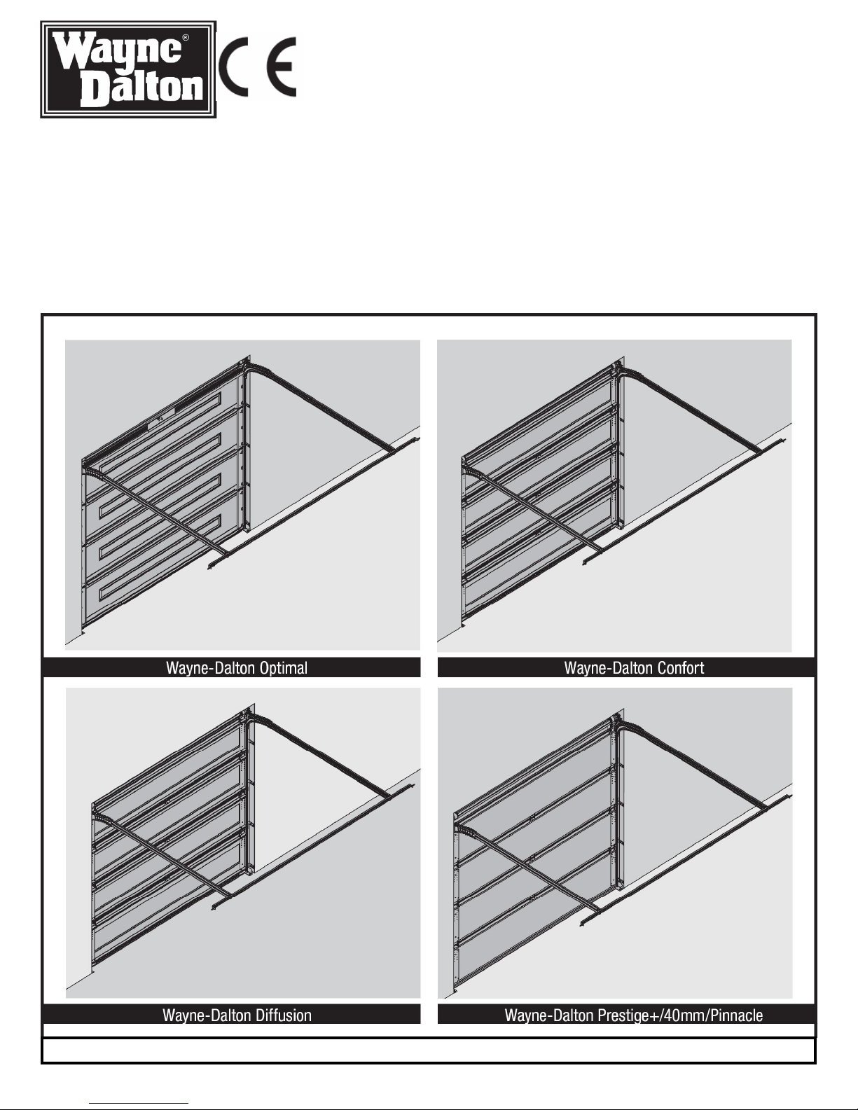
Models: Wayne-Dalton Optimal, Wayne-Dalton Confort,
Wayne-Dalton Europe
1 Rue Maurice Hollande
51100 Reims, France
www.waynedaltoneurope.com
NOTE: THIS NOTES MANUAL MUST BE ACCOMPANIED BY THE DRAWINGS MANUAL, PART NR. 324623.
© Copyright 2005 Wayne-Dalton Corp.
Part Nr. 324624 - ENGLISH REV1 01/20/2006
Wayne-Dalton Diffusion, Wayne-Dalton Prestige+/40mm/Pinnacle
Page 2

TABLE OF CONTENTS
Notes of Installation, Use, and Maintenance
Definition Of Symbols ..................................................................................................................................................... 3.
Important Safety Instructions For Installation .................................................................................................................. 3.
Package Contents ........................................................................................................................................................... 4.
Required Tools ................................................................................................................................................................ 4.
“INSTALLATION”
Door Assembly Mounting .......................................................................................................................................... 5.
Horizontal Track Mounting ........................................................................................................................................ 5.
Spreader Bar Pre-mounting ...................................................................................................................................... 6.
Back Hanging Horizontal Track, Spreader Bar And Manual Door Testing ............................................................... 6.
Striker Plate Mounting (If required) ........................................................................................................................... 7.
CE / Serial Number Label ......................................................................................................................................... 7.
Spring Adjustments (If required) ............................................................................................................................... 7. - 8.
External Electrical Operator Installation (If required) ................................................................................................ 8.
“MAINTENANCE”
Dismantle / Discard ................................................................................................................................................... 8.
Opening And Closing ................................................................................................................................................ 8.
Locking And Unlocking ............................................................................................................................................. 8.
Monthly Maintenance ................................................................................................................................................ 9.
Service / Repair ........................................................................................................................................................ 9.
Maintenance / Painting ............................................................................................................................................. 10.
Limited Warranty ............................................................................................................................................................. 11.
Manufacturer’s Declaration Of Conformity ...................................................................................................................... 12.
Website ........................................................................................................................................................................... 12.
After installation is complete, fasten this manual near the garage door. Perform monthly maintenance (see maintenance section on page 9) and periodic
checks, as recommended.
2
Page 3

DEFINITION OF SYMBOLS
WARNING
ATTENTION - Risk Of Injury
WARNING IT IS VITAL FOR THE SAFETY OF PERSONS TO FOLLOW ALL
INSTRUCTIONS.SAVE THESE INSTRUCTIONS.
1. READ AND FOLLOW ALL INSTALLATION INSTRUCTIONS.
2. Wear eye protection when using tools to install, repair, or adjust door or opener to prevent eye injuries.
3. Wear protective gloves to install, repair, or adjust door or opener to avoid hand injuries.
4. The door system should not be installed and is not intended for use in an explosive environment.
5. Door is under extreme spring tension. To prevent possible injury, repairs or adjustments not covered in this manual should
only be performed by an authorized, qualified door system service representative.
6. Operate door only when properly installed, properly adjusted and free of obstructions.
7. The door should not be installed in a corrosive environment.
8. The door is designed to operate in an ambient temperature range of -40°C (-40°F) to 57°C (135°F).
9. Avoid standing in open doorway or walking through doorway while door is moving. Do not go under a stopped, partially open
door.
10. After installation, ensure that the parts of the door do not extend over public footpaths or roads.
11. Keep away from the all moving parts of the door and opener system while the system is being operated.
12. Watch the moving door and keep people, and objects away from the door until the door is completely closed. NO ONE
SHOULD CROSS THE PATH OF A MOVING DOOR.
13. KEEP THE GARAGE DOOR PROPERLY BALANCED. An improperly balanced door could cause severe or fatal injury.
Have an authorized, qualified door system representative make repairs to the cables, spring assemblies, and other hardware.
3
Page 4

Note: Use these notes of installation, Use, and Maintenance in conjunction with the Drawings of installation, Use, and maintenance to perform the
installation. The following letters & numbers in parenthesis, [example: (a1)] cross reference items listed in each diagram of the Drawings of Installation,
Use, and Maintenance manual.
PACKAGE CONTENTS
PACKAGE CONTENTS “A” (SEE PAGE 2 OF DRAWINGS OF INSTALLATION, USE AND MAINTENANCE MANUAL)
CALL OUTS PARTS QUANTITY
A1 Pre-assembled Door 1
A2 Horizontal Track 1 pair
A3 Yellow And Black Warning Label 1
A4 Spreader Bar Assembly * 1
[*Attached to the bottom door section during packaging]
A4.1 Spreader Bar 1
A4.2 Slider Bars ** 2
A4.3 “L” Bracket ** 2
[**Attached To Spreader Bar]
A5 “L” Bracket 2
A6 Ø 6 x 15 mm (1/4” - 20 x 9/16”) Track Bolt 10
A7 Ø 6 mm (1/4” – 20) Flange Hex Nut 10
A8 Ø 8 x 40 mm (5/16” x 1-5/8”) Lag Screw 13
A9 Striker Plate 1
A10 Molded Transition Track 1 Pair
A11 Anchors 13 (not supplied)
TOOLS REQUIRED “B” (SEE PAGE 3 OF DRAWINGS OF INSTALLATION, USE AND MAINTENANCE MANUAL)
CALLOUTS PARTS QUANTITY
B1 Electric Drill (With Clutch) 1
B2 5 mm (3/16”) Drill Bit 1
B3 Level 1
B4 Ratchet Wrench 1
B5 75 mm (3”) extension 1
B6 11 mm (7/16”) Wrench 1
B7 Tape measure 1
B8 Screw Driver (Flat Head) 1
B9 Step ladder 1
B10 Safety Glasses 1
B11 Gloves 1
B12 11 mm (7/16”) Hex Head Driver 1
4
Page 5

Installation
IMPORTANT: Stainless steel lag screws or PT2000 coated lag screws must be used when installing center bearing brackets, end bearing brackets, jamb
brackets, operator mounting / support brackets and disconnect brackets on treated lumber (preservative-treated). Stainless steel or PT2000 coated lag
screws are not necessary when installing products on un-treated lumber.
NOTE: Pilot drilling, using a 5mm (3/16”) drill bit (B2), is recommended when fastening ø8x40mm (5/16” x 1 5/8”) lag screws (A8) into wood structure.
IMPORTANT: Right and left hand is always determined from inside the building looking out.
Door Assembly Mounting
1
(See Diagram 1 on page 3 of Drawings of Installation, Use and Maintenance manual)
Tools Needed:
Electric Drill (With
Clutch)
5mm (3/16”) Drill Bit
Level
Tape Measure
Step Ladder
11mm (7/16”) Hex
Head Driver
11mm (7/16”)
Wrench
NOTE: Spreader bar will always be shipped at the bottom of the door assembly (A1) to secure the door frame. To ensure
proper door spacing and alignment, do not remove the spreader bar assembly (1a) until door frame is secured to the jamb and
bottom plate (1b) is anchored to the floor.
NOTE: TorqueMaster
III counterbalance system or serious injury may occur.
NOTE: Do not operate emergency disconnect handle until frame, horizontal track, and spreader bar are completely installed.
NOTE: Start assembly / installation process only after door assembly is positioned vertically in the opening.
Remove the shipping brackets (1c) by removing the two screws (1d) and bolt (1e). Re-install the two screws (1d) to secure the
top brackets (1f) to the top section, as shown in FIG. 1.1. Repeat for right hand side.
Starting on the left side, align the outside edge of flagangle (1i) with the groove of the molded transition track (A10). Slide the
molded transition track assembly into position until the slot (1j) in flagangle aligns with hole (1k) in the molded transition track.
Secure molded transition track assembly to flagangle with one Ø6 x 15mm (1/4” - 20 x 9/16”) track bolt (A6) and Ø6mm (1/4” -
20) flange hex nut (A7), as shown in FIG. 1.2 and 1.3. Repeat for right hand side.
NOTE: ensure the Ø6 x 15mm (1/4” - 20 x 9/16”) track bolt is going through the molded transition track first, and the Ø6mm
(1/4” - 20) flange hex nut is on the outside of flagangle, as shown in FIG. 1.3.
NOTE: Check for smooth transition between molded transition track (A10) and top of vertical track (1m), as shown in FIG. 1.3.
Place the door frame (A1) into the door opening. level (B3) the door frame horizontally and vertically. Secure leveled door frame
with proper anchors (A10) and Ø8 x 40mm (5/16” x 1-5/8”) lag screws (A8) through the four jamb brackets (1g), as shown in
FIG. 1.4 and FIG. 1.5. Secure the angle bracket located on the left hand side of the opener (1x), to the ceiling using one proper
anchor (A10) and one Ø8 x 40mm (5/16” x 1-5/8”) lag screw (A8) through the slotted hole in the angle bracket (2o), as shown in
FIG. 1.6. Once the angle bracket is secured to the ceiling, tighten the Ø6mm (1/4” - 20) flange hex nut (A7).
NOTE: ensure that the angle bracket is secured to a ceiling joist or other structurally sound framing member and not just into
drywall or into paneling.
Secure the bottom plate (1b) to the floor with one Ø8 x 40mm (5/16” x 1-5/8”) lag screw (A8) and anchor (A10), as shown in
FIG. 1.5. Repeat for opposite side.
® III counterbalance system and cables are under extreme tension! Never tamper with the TorqueMaster®
2
Tools Needed:
11mm (7/16”) Wrench
Screw Driver (Flat
Head)
Slide the horizontal track (A2) into the groove of the molded transition track (A10) and secure with one Ø6 x 15mm (1/4”
- 20 x 9/16”) track bolt (A6) and Ø6mm (1/4” - 20) flange hex nut (A7), as shown in FIG. 2.1. Repeat for other side.
NOTE: On some models this may already have been done at the factory.
NOTE: ensure the Ø6 x 15mm (1/4” - 20 x 9/16”) track bolt is going through the inside of horizontal track first, and the
Ø6mm (1/4” - 20) flange hex nut is on the outside of the molded transition track, as shown in FIG. 2.1.
Remove the spreader bar assembly (1a) from the door frame by removing the Ø6 x 15mm (1/4” - 20 x 9/16”) track bolts
(A6) and Ø6mm (1/4” - 20) flange hex nuts (A7), as shown in FIG. 2.4. Repeat for other side. Set the spreader bar assembly
with the Ø6 x 15mm (1/4” - 20 x 9/16”) track bolts and Ø6mm (1/4” - 20) flange hex nuts aside.
(See Diagram 2 on page 4 of Drawings of Installation, Use and Maintenance manual)
Horizontal Track Mounting
5
Page 6

3
Spreader Bar Pre-Mounting
(See Diagram 3 on page 5 of Drawings of Installation, Use and Maintenance manual)
Tools Needed:
11mm (7/16”) Wrench
Screw Driver (Flat
Head)
4
Tools Needed:
Electric Drill (With
Clutch)
5mm (3/16”) Drill Bit
11mm (7/16”) Wrench
Tape Measure
Screw Driver (Flat
Head)
Step Ladder
11mm (7/16”) Hex
Head Driver
Attach the “L” bracket (A4.3) to the right side of the slider bar (A4.2) with one ø6x15mm (1/4” - 20 x 9/16”) track bolt (A6) and
ø6mm (1/4” – 20) flange hex nut (A7), as shown in FIG. 3.1. Repeat for other slider bar.
Attach the “L” bracket (A5) to the right hand horizontal track (A2) with one ø6x15mm (1/4” - 20 x 9/16”) track bolt (A6) and
ø6mm (1/4” – 20) flange hex nut (A7), as shown in FIG. 3.2. Repeat for the left hand side.
Back Hanging Horizontal track and Spreader Bar And Manual Door
Testing
(See Diagram 4 on page 5 of Drawings of Installation, Use and Maintenance manual)
Adjust the width of the spreader bar (A4.1), by adjusting the slider bar (A4.2) “In and Out” to the approximate width of the side
walls or perforated angle (not provided) if mounting to the ceiling, as shown in FIG. 4.1. Attach the right hand side of the
spreader bar (A4.1) with one Ø6 x 15mm (1/4” - 20 x 9/16”) track bolt (A6) and Ø6mm (1/4” - 20) flange hex nut (A7) to the “L”
bracket (A5) at the horizontal track extremity. Repeat for the left hand side.
NOTE: Make certain the track is level and perpendicular to the door (A=B).
Secure the “L” bracket (A4.3) on the slider bar (A4.2) to the wall with one anchor (A11) (if necessary) and one Ø8 x 40mm
(5/16” x 1-5/8”) lag screw (A8). If fastening into drywall or concrete, proper anchors will need to be used. Use one Ø6 x 15mm
(1/4” - 20 x 9/16”) track bolt (A6) and Ø6mm (1/4” - 20) flange hex nut (A7) for attaching to perforated angle (not provided).
Repeat for the left hand side. Verify that the tracks (A2) are level and perpendicular to the inside face of the door, adjust slider
bars (A4.2) if necessary, as shown in FIG. 4.2. Re-check dimensions (A=B) to ensure they have not changed, as shown in FIG.
4.3.
MANUALLY TESTING THE FUNCTIONING OF THE DOOR
Before performing Step 5 (Striker Plate Mounting (If Required)), it is NECESSARY to check the manual operation of the door, to
ensure that it operates easily.
TEST 1:
Lift the door slowly checking that the torque tube turns until the door is fully open. Check that the counterbalance cables are
wound correctly on their respective drums.
TEST 2:
Check for proper counterbalance of the door: positioning it at mid-height, the door should remain in position. It should neither go
up, nor fall under its own weight. Adjust spring(s), if door lifts by itself and is hard to pull down, or if door is difficult to lift and
comes down by itself. Refer to Step 7, Spring Adjustment (If Required). Also check that the distance between the door and the
horizontal tracks is identical on the left and right side.
Once these checks have been made, close the door.
6
Page 7
5
Striker Plate Mounting (If Required)
(See Diagram 5 on page 6 of Drawings of Installation, Use and Maintenance manual)
Tools Needed:
11mm (7/16”)
Wrench
Screw Driver
(Flat Head)
6
Tools Needed:
None
7
IMPORTANT: If the door is electrically operated, the secure lock MUST NOT be installed. In which case, skip this step.
Locate desired side of door for striker plate placement. Locate the striker plates over the pre-punched holes in the vertical track
on the selected side, nearest the center of the lock (second) section. Fasten the striker plate to the vertical track (1m) using two
ø6x15mm (1/4” - 20 x 9/16”) track bolts (A6) and ø6mm (1/4” – 20) flange hex nuts (A7).
CE / Serial Number Label
(See Diagram 6 on page 6 of Drawings of Installation, Use and Maintenance manual)
When all steps of the installation are completed and door is ready for use, remove the strip covering the CE/ Serial Number
Label (1p). This label is located on the end stile (1o) of the door’s top section (1n).The limited Warranty is conditioned upon
exact compliance with the Manufacturer’s Notes of Installation, Use and Maintenance manual.
Place the yellow and black warning label (A3) on the lock section as shown.
Note: The lock section can be identified by the CE / Serial number Label (1p) attached to the right side of the section.
Spring Adjustment (If Required)
(See Diagram 7 on page 6 of Drawings of Installation, Use and Maintenance manual)
Tools Needed:
Ratchet Wrench
75mm (3”)
Extension
NOTE: The counterbalances system is pre-set at the factory, due to different materials and application a small adjustment may
be needed.
WARNING COUNTERBALANCE SYSTEM AND CABLES ARE UNDER EXTREME TENSION! ALL ADJUST-
MENTS SHOULD ONLY BE PERFORMED BY AN AUTHORIZED, QUALIFIED DOOR SYSTEM
SERVICE REPRESENTATIVE.EXTREME CARE NEEDS TO BE TAKEN DURING THIS PROCESS.
Lift the door and check its balance. Adjust spring, if door lifts by itself and is hard to pull down, or if door is difficult to lift and
comes down by itself. A ¼” square tool (ratchet wrench) (B4 and B5) is required to wind TorqueMaster® springs. With the door
fully down, clamp mole grips (locking pliers) on horizontal track just above top roller. To adjust springs, only add or remove 3/10
of a turn (3 teeth of ratchet wheel) maximum at a time. Adjust both sides equally.
IMPORTANT: On some models, the TorqueMaster® is provided with only ONE SPRING, the right one. In this case, the
following operations are to be made only for the right side.
WARNING BE PREPARED TO HOLD THE FULL TENSION OF THE SPRING
ADJUSTMENT + ADDING TENSION:
Insert wrench (B4 and B5) on the outside of the TorqueMaster (1q), ensure tool seats firmly inside, as shown in FIG. 7.1. Gently
pull wrench (B4 and B5) downwards (counter clockwise for the right side, clockwise for the left side) enough to release the pawl
(1s), as shown in FIG. 7.3. Pull down (counter clockwise for the right side, clockwise for the left side) to add tension to the
spring. When desired tension is achieved, re-engage the pawl (1r) by pushing on it with a finger, ensuring it seats properly in
between the teeth of the gear (1t) as shown in FIG 7.2, and then, gently release the wrench (B4 and B5) (clockwise for the right
side, counter clockwise for the left side), until pawl is engaged in the gear. Carefully remove the wrench (B4-B5) from gear (1q).
In case of TorqueMaster® with two springs, repeat for opposite side, until desired tension is achieved.
ADJUSTMENT – RELEASING Of TENSION:
Insert wrench (B4 and B5) on the outside of the TorqueMaster (1q), ensure wrench seats firmly inside, as shown in FIG. 7.1.
Gently pull wrench (B4 and B5) downwards (counter clockwise for the right side, clockwise for the left side) enough to release
the pawl (1s), as shown in FIG. 7.3.
7
Page 8

7
Spring Adjustment (If Required) - Continued
(See Diagram 7 on page 6 of Drawings of Installation, Use and Maintenance manual)
Tools Needed:
Ratchet Wrench
75mm (3”)
Extension
Let wrench rotate clockwise for the right side, counter clockwise for the left side until desired tension is achieved as shown in
FIG. 7.3. Re-engage the pawl (1r) by pushing on it with a finger, ensuring it seats properly in between the teeth of the gear (1t),
as shown in FIG. 7.2, and then, gently release the wrench (B4 and B5) clockwise for the right side, counter clockwise for the left
side, until pawl is engaged in the gear. Carefully remove the wrench from gear. In case of TorqueMaster® with two springs,
repeat for opposite side, until desired tension is achieved.
External Electrical Operator Installation (If Required)
(see : Manual of Installation supplied with the operator)
After and only after spring adjustment and door balance checked, the installation of an external electrical operator is possible.
DISMANTLE AND DISCARDMENT
To dismantle the installed garage door system, remove the garage door system in the reverse order in which it was installed in the installation section of
this manual. Check local codes for proper discardment.
OPENING AND CLOSING
To open the door, rotate either the inside or outside handle 45 degrees until the handle locks into place and the door lock unlatches. Use the furnished
handles to open and close the door manually.
On closing the door, ensure the door latches securely when completely closed by rotating the handle back to the original position.
LOCKING AND UNLOCKING
The door does not automatically lock when closed manually. To lock and unlock the door, use the provided key or the locking pin.
FROM THE OUTSIDE:
To unlock: Turn the key counterclockwise 360°.
To lock: Turn the key clockwise 360°.
FROM THE INSIDE:
To unlock: Push the locking pin down.
To lock: Push the locking pin up.
NOTE: If using the door with an automatic garage door opener, the door lock must be removed or made in operative, in unlock position.
Use the provided key.
Actuate the locking pin on the lock.
8
Page 9
MONTHLY MAINTENANCE
WARNING
KEEP AWAY FROM ALL MOVING PARTS OF THE DOOR AND OPENER SYSTEM WHILE THE SYSTEM IS BEING OPERATED.
WARNING
NEGLIGENT OR IMPROPER MAINTENANCE INCREASES THE RISK OF INJURY TO PERSONS AND DAMAGE TO PROPERTY.
WARNING
TORQUEMASTER™ COUNTERBALANCE SYSTEM AND CABLES ARE UNDER EXTREME TENSION! NEVER TAMPER WITH THE
TORQUEMASTER™ COUNTERBALANCE SYSTEM OR SERIOUS INJURY MAY OCCUR.
The following maintenance procedures should be performed every six months by a competent person:
1. Visually inspect all moving components during normal operation of the door system.
2. Open door completely and close door. If the door feels unbalanced or binds have an authorized, qualified door system service representative make
adjustments to door.
Door cables:
Check door cables for signs of wear or fraying. If cables need replacing, contact a qualified authorized, door service representative.
Spring tension:
To check spring tension: Open the door halfway. The springs should hold the door in this position. Should the door slide down or raise on its
own, contact a qualified authorized door service representative to adjust the spring tension.
Fixing points:
Check all fixing points, ensuring that they are firmly secured. Tighten any loose screws and/or bolts.
Track rollers and door track:
The door should open and close smoothly. Ensure the door rollers are rotating freely when opening and closing the door. Should the rollers not
turn easily or not turn at all: Clean the door track, removing dirt and any foreign substances. Clean and lubricate rollers inside of roller guides.
Do not lubricate the door track.
Cylinder lock:
Do not oil cylinder lock! If actuation is difficult, lubricate the lock with graphite dust.
SERVICE / REPAIR
TorqueMaster™ springs are designed to provide service life of 10,000 cycles. Springs will need to be replaced in approximately 5 ½ years if you operate
your door 5 times a day.
Door hardware (Hinges, rollers, Counterbalance cables, Track etc.) are designed to provide service life of 40,000 cycles. To obtain a copy of the
counterbalance cable tensile strength documentation, contact your local authorized dealer or manufacturer.
WARNING
DO NOT ATTEMPT TO REPAIR OR SERVICE ANY DAMAGED DOOR YOURSELF. FOR ALL SERVICE AND REPAIRS, CONTACT A
QUALIFIED AUTHORIZED DOOR SERVICE REPRESENTATIVE.
9
Page 10

MAINTENANCE / PAINTING INSTRUCTIONS FOR PRE-PAINTED DOORS
MAINTENANCE
While factory-applied finishes on steel garage doors are durable, it is desirable to clean them on a routine basis. Some discoloration of the finish may
occur when a door has been exposed to dirt-laden atmosphere for a period of time. Slight chalking may also occur as a result of direct exposure to
sunlight. Cleaning the door will generally restore the appearance of the finish. To maintain an aesthetically pleasing finish of the garage door, an annual
washing of the door is recommended. A mild solution of detergent and water will aid in the removal of most dirt. The following solution mixture is
recommended: One cup of Tide™, or other common detergents, which contain less than 0.5% phosphate, dissolved into five gallons of warm water.
CAUTION: NEVER MIX CLEANSERS OR DETERGENTS WITH BLEACH.
SURFACE PREPARATION FOR PAINTING
Wax on the surface must be removed or paint peeling/flaking will result. To remove this wax, it will be necessary to lightly scuff the surface with a fine
steel wool pad, saturated with soapy water. A final wipe and rinse should be done with clean water only, to remove any loose particles and any soapy
film residue. Surface scratches, which have not exposed the metal substrate, can be lightly buffed or sanded with 0000 steel wool or no. 400 sand paper
to create a smoother surface. Care must be taken to not expose the substrate under the paint (see NOTE no. 2). Once the substrate is exposed, the
likelihood for rusting is greatly increased. See the following paragraph if metal substrate is observed. The exposed substrate must be treated to prevent
rust from forming (see NOTE no. 2). Sand the exposed area lightly and paint with a high quality metal primer, specifically intended for galvanized
surfaces, to protect the area from corrosion. Follow drying time on primer can label before applying topcoat. The surface of the factory-applied finish, that
is being painted, must not be too smooth, or the paint will not adhere to it (see NOTE no. 2). It is advisable to test in an inconspicuous area, to evaluate
adhesion. If poor adhesion is observed, surface preparation for painting the factory- applied finish must be repeated until desired results are achieved.
Again, care must be taken to not expose the substrate under the paint.
PAINTING
After the surface has been properly prepared it must be allowed to dry thoroughly, then coated immediately with premium quality latex house paint.
Follow the paint label directions explicitly. Oil base, or solvent base paints are not recommended. Please note that if substrate is exposed and not
properly primed, painting with latex paint may cause accelerated rusting of the steel in the exposed area.
NOTE:
1. Repainting of finish painted steel doors cannot be warranted, as this condition is totally beyond the door manufacturer’s control.
2. If the finish painted steel door surface has a textured surface representing wood grain, stucco, etc., this step should not be attempted as danger of
exposing substrate is greatly increased.
3. Consult a professional coatings contractor if in doubt about any of the above directions.
4. Follow directions explicitly on the paint container labels for proper applications of coatings and disposal of containers. Pay particular attention to
acceptable weather and temperature conditions in which to paint.
DÉCOR LITES ACRYLIC GLAZING CLEANING INSTRUCTIONS:
1. Clean acrylic glazing with nonabrasive soap or detergent and plenty of water. Use your bare hands to feel and dislodge any caked on particles a soft,
grit-free cloth, sponge or chamois may be used to wipe the surface. Do not use hard or rough cloths that will scratch the acrylic glazing. Dry glazing with
a clean damp chamois.
2. Kerosene may be used to remove grease and oil. When using kerosene for cleaning purposes, make sure that you are familiar with its proper ties,
using it only in a well ventilated area away from any sources of sparks and/or fire.
3. DO NOT USE: Window cleaning fluids, scouring compounds, gritty cloths, gasoline, or solvents such as alcohol, acetone, carbon tetrachloride, etc.
10
Page 11

Wayne-Dalton Optimal, Wayne-Dalton Confort, Wayne-Dalton Diffusion, and
Wayne-Dalton Prestige+/40mm/Pinnacle
LIMITED WARRANTY
1. The manufacturer (Wayne-Dalton Corp.) warrants the Optimal steel garage door sections from the time of installation, for a period of ten years against
structural failure of the door section(s) (rendering the door inoperable) due to separation / degradation of the foam insulation.
2. The manufacturer also warrants the above referenced steel garage door sections from the time of installation, for a period of ten years against
deterioration such as cracking or splitting due to rust-through.
3. The manufacturer warrants the garage door hardware, track, and springs for the above referenced steel garage door system for a period of two years
from the time of installation against defects in material or workmanship.
4. The above conditions apply provided that the above referenced insulated steel garage door is properly installed, used, maintained, and serviced in
accordance with the Manufacturer’s Notes of Installation, Use and Maintenance under normal residential use and service.
5. This limited warranty extends only to the original purchaser, provided the above referenced insulated steel garage door and is properly installed, used,
maintained, and serviced in his/her place of primary residence. This limited warranty is not transferable. This limited warranty applies to residential
property only and is not valid on commercial or commercial rental property.
6. This limited warranty covers a consumer product as defined by Directive 1999/44/eC of the European Parliament and of the Council of 25 may 1999
(herein referred to as the Directive) on certain aspects of the sale of consumer goods and associated guarantees. No warranties, expressed or implied,
shall extend beyond the applicable time periods as set forth above. The above warranties and warranty language shall also not operate to extend any
rights granted by the above referenced Directive or any applicable Member State provision of national law beyond the dates specified in said Directive or
provision of national law.
7. The Manufacturer shall, upon notification, correct product non conformities by repairing, replacing, or refunding the original purchase price of any
defective part(s). The charges that will be covered include those as listed in the above referenced Directive.
8. No employee, distributor, or other representative is authorized to change the foregoing limited warranty in any way or grant any other warranty on
behalf of the Manufacturer.
9. The Manufacturer shall not be responsible for damage resulting to or caused by its products by reason of improper installation, improper storage,
unauthorized service, alteration of products, neglect or abuse, or attempt to use the products for other than the customary usage or for their intended
purposes. This limited warranty is null and void if any above referenced insulated steel garage door section is punctured with any hole or if a hole is
drilled into any door sections other than those specified in the Manufacturer’s Notes of Installation, Use and Maintenance.
10. Claims for defects in material and workmanship covered by this limited warranty shall be made in writing to the distributor from whom the product was
purchased within the warranty period. The Manufacturer may either send a service representative or have the product returned to the Manufacturer for
inspection. If judged by the Manufacturer to be defective in material or workmanship, the product will be replaced or repaired at the option of the
Manufacturer, free from charges as described in the Directive.
11. The remedies of the purchaser set forth herein with respect to the express limited warranties referenced herein are exclusive and are in lieu of all
other remedies. The liability of the Manufacturer, whether in contract, tort, or pursuant to any other types of liability under the applicable system of law, or
under any limited warranty or otherwise, shall not extend beyond its obligation to repair or replace, at its option, any product or part found by
Manufacturer to be defective in material or workmanship. The Manufacturer shall not be responsible for any direct, indirect, special, or consequential
damages of any kind or nature.
12. The legal rights which you, the purchaser, are granted under applicable national legislation governing the sale of consumer goods are not affected by
this limited warranty.
13. This limited warranty is conditioned upon exact compliance with the Manufacturer’s Notes of Installation, Use and Maintenance which accompany the
above referenced insulated Steel Garage Door.
11
Page 12
MANUFACTURER’S DECLARATION OF CONFORMITY
Garage Door Models: Wayne-Dalton Optimal, Wayne-Dalton Confort, Wayne-Dalton
Diffusion, Wayne-Dalton Prestige+/40mm/Pinnacle
is in conformity to the applicable sections of Door Standards EN 292, EN 294, EN 349, EN 418, prEN894, EN 1037,
EN 1088, EN 12424, EN 12444, EN 12453, EN 12604,
EN 60204-1
Per the provisions & all amendments of the EU Directives 73/23/EEC, 89/336/EEC, 89/392/EEC, 89/106/EEC
Declaration of Conformity
The above listed garage door models, when installed and maintained according to all the Manufacturer’s Instructions, meet the provisions of the above
listed EU Directives and all amendments.
I, the undersigned, hereby declare that the equipment specified above, as well as any accessories to such equipment listed in the Notes of Installation,
Use, and Maintenance conform to the above listed Directives and Standards.
Signature of manufacturer:
François Médart – President Wayne-Dalton Europe January 20, 2006
Place: Wayne-Dalton Europe
1 rue Maurice Hollande
51100 Reims, France
Please Do Not Return This Product To The Store
Questions?
Need Information?
Visit our website:
www.waynedaltoneurope.com
Thank you for your purchase
Models: Wayne-Dalton Optimal, Wayne-Dalton Confort, Wayne-Dalton Diffusion, Wayne-Dalton Prestige+/40mm/Pinnacle
Covered under one or more of the following U.S. patents:
D413,055/D413,579/D413,867/D421,031/D466,141/D472,568/D472,910/D473,573/D473,574/D474,215/D475,146/5,259,143/5,408,724/5
,409,051/5,419,010/5,929,580/5,931,212/6,078,249/6,145,570/6,164,014/6,253,824/6,263,947/6,325,134/6,326,751/6,326,754/6,401,7
92/6,442,897/6,561,255/6,561,256/6,568,454/6,605,910/6,588.156/6,640,872/6,667,591/6,672,362/6,739,372/6,899,157
European Patent: EP0975417 other U.S. and foreign patents pending.
12
 Loading...