


DS-50/DS-75/DS-100 MINI ROLL-UP DOORS
INSTALLATION INSTRUCTIONS
IMPORTANT NOTICE !!
Read the enclosed instructions carefully before attempting to install this door. Pay close attention to all warnings and important safety notices.
This manual MUST be attached to the wall in close proximity of the door.
©Copyright 2004 Wayne-Dalton
P/N 300847, DOC #101-0117 REV 03
IMPORTANT SAFETY NOTICES
Read the enclosed instructions carefully before attempting installation. If there are any questions about any of the procedures, do not perform the work. Instead, have a trained door technician do the installation or repairs.
1.Operate the door ONLY when it is properly adjusted and free of all obstructions.
2.The door is constantly under EXTREME SPRING TENSION. Repairs, adjustments, installation and removal, ESPECIALLY of SPRINGS AND RELATED PARTS, are dangerous. Such work should be performed ONLY by trained door technicians.
3.DO NOT PERMIT children to play with the door. Children could get caught between the door and the floor causing severe injury or death.
4.Avoid standing in the open doorway or walking through the doorway while the door is moving. One could get caught between the door and the floor causing severe injury or death.
5.Should the door become hard to operate or completely inoperative, it is recommended that a trained door technician correct the problem to prevent possible injuries or door damage.
6.Avoid installing the door on windy days. The door could fall causing personal injury or door damage.
7.To prevent injuries due to loose components, at least monthly check all bolted connections to make sure they are secure.
8.To prevent injuries, never place hands or fingers between the curtain and the guides while the door is being operated.
9.This manual is not intended to provide "take-down" instructions for existing doors. Consult your local door agency if this is required, before new doors are to be installed.
10.Thoroughly familiarize yourself with the building codes in your region before initiating work.
11.Wear the proper protective safety gear at all times when installing, adjusting, and/or repairing doors.
12.Use a 2-person (or larger) crew for installing, adjusting, and/or repairing larger doors.
13.Definitions of key words used in this manual are as follows:
This is the safety alert symbol. It is used to alert you to potential personal injury hazards. Obey all safety messages that follow this symbol to avoid possible injury or death.

 WARNING
 CAUTION
CAUTION
IMPORTANT!
WARNING indicates a potential hazardous situation which, if not avoided, could result in serious injury or death.
CAUTION indicates a potentially hazardous situation which, if not avoided, may result in minor or moderate injury.
CAUTION used without the safety alert symbol indicates a potentially hazardous situation which, if not avoided, may result in property damage.
IMPORTANT! indicates a required step for safe and proper door operation.
NOTE:
HINT:
NOTE: indicates information assuring proper installation of the door.
HINT: indicates a suggested step to simplify installation based on experience.
2
INTRODUCTION
This manual's main function is to assist the installer in correctly installing the doors to ensure safe operation. Compliance with building codes, enforced in your area, is required.
All Wayne-Dalton DS-50, DS-75, and DS-100 Mini Roll-Up Doors follow these general instructions. Additional installation information for the specific door shipped is found with the packing slip and on supplementary drawings. There are also bolt and small sealed parts bags with accessory lists, describing proper application.
PREPARATION
Read the installation instructions thoroughly to become familiar with the names of the various components and their relation to each other. It is necessary for the installer to determine the following:
Type of jamb material (wood, masonry, or steel) on which the door guides will be mounted.
The dimensions for the opening width, opening height, headroom, and side room.
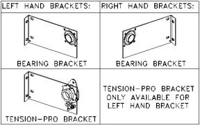
Type of support brackets provided (bearing bracket or Tension-Pro™ bracket).
MATERIAL
Inspect your door for possible damage or shortage of parts. Immediately report any shortages to your door supplier, or transit related damage claims to your freight carrier.
CLEARANCES
Compare the door opening dimensions and available clearances against the dimensions listed on the packing slip, taking special note of the opening width and height.
TOOLS
Commonly used tools for proper installation are:
Electric drill with 3/8" or 1/2" chuck with nut driver and drill bits.
Masonry drill or impact hammer and bits.
Ladders and/or scaffolding.
Hammer and pliers.
Large Pipe Wrench (if Tension-Pro bracket).
Center punch and Screwdrivers.
Wrenches, vise grips, and C-clamps.
Tape measure and a water level.
FASTENER TABLE
Jamb Condition |
Bracket Fasteners |
Guide Fasteners |
Wood |
5/16 x 1-1/2” Lag Screw |
5/16 x 1-1/2” Lag Screw |
Masonry |
5/16 x 1-1/2” Wedge Anchor |
1/4 x 1-3/4” Tapcon |
Steel |
1/4 x 3/4” Self Drilling |
1/4 x 3/4” Self Drilling |
|
Screw |
Screw |
3
STEP 1 UNPACKING DOORS
Before removing the door from any packaging, inspect the packaging for visible signs of damage. If damage is noted, file a freight claim with the freight company immediately. Remove the door from the packaging.
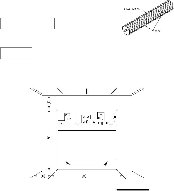
Do not cut tape that holds door IMPORTANT! in a roll. You will be told in STEP
#7 when to cut the tape.
No guarantee will be given by Wayne-Dalton if the door is not installed as
instructed. Please review all instructions thoroughly before starting installation. For proper operation, follow these instructions step by step.
NOTE: Rightside. and Left Hand is determined by facing the door opening, on the coil
STEP 2 CHECKING THE DOOR OPENING
Verify that dimensions W and H (see below) match those recorded on the door packing slip. Consult the factory if the actual opening width is greater than that shown on the packing slip by more than 1-1/2 inches. Check to make certain that the door opening is square and plum and that the floor is level. Check to be certain there is sufficient clearance from the opening to the ceiling and the sidewalls (see Required Clearances below).
OPENING HEIGHT |
HEADROOM (A) |
|
SIDE ROOM (B) |
|
|
|
|
|
|
|
|
UP TO 6’8” HIGH |
13” |
|
4” |
|
|
|
|
FROM 6’8-1/4” TO 8’ HIGH |
14” |
|
4” |
|
|
|
|
OVER 8’ HIGH |
16” |
|
4” |
|
|
|
|
REQUIRED CLEARANCES - MINIMUM INDICATED
4
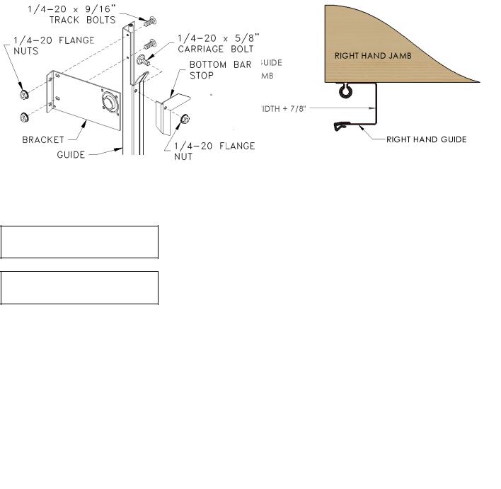
STEP 3 INSTALLING GUIDES
Position the left hand guide 3/8” from the edge of the left hand jamb and loosely clamp in place. Using a level, adjust the guide so that it is plumb and tighten the clamp.
Measure the exact curtain width of the door and add 7/8” to obtain the inside of guide to inside of guide measurement. Use this measurement to locate the right hand guide. Loosely clamp the right hand guide to the jamb. Plumb the guide and tighten the clamp.
Using a string and level, ensure that the tips of the left and right hand guides are level to each other. Shim guides as needed. Double check the inside of guide to inside of guide measurement at top, middle, and bottom to ensure that the guides are plumb and parallel. Fasten both guides to the jambs using the fasteners provided (See Fastener Table in the front of this manual).
IMPORTANT!
IMPORTANT!
Inside of guide to inside of guide measurement must be held to ensure proper door operation.
Use of any other fasteners than those provided must be approved by Wayne-Dalton and cannot be of lesser diameter or grade.
STEP 4 INSTALLING BRACKETS
Install the brackets to the outside of the guides (away from the opening) using two 1/4-20 x 9/16” track bolts in the two holes at the top of the guides, as shown. Loosely install the 1/4-20 flange nuts on the bolts to hold the brackets in place. Check that the brackets are straight and square with one another, shimming if necessary, and fasten the brackets to the wall using the fasteners provided (See Fastener Table in the front of this manual). Tighten the flange nuts on each bracket.
Install the bottom bar stops to the guides as shown using 1/4-20 x 5/8” carriage bolts and flange nuts. Leave the fasteners loose to allow the bottom bar stops to pivot out of the way of the bottom bar angle when the curtain will be pulled into the guides. You will be instructed to tighten the bottom bar stop fasteners in STEP #7.
5
 Loading...