

Page 1
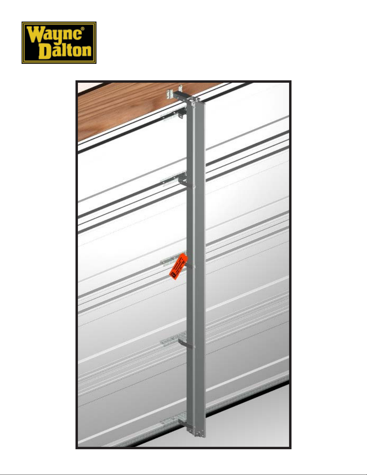
Windload Post
9100/9600/99009100/9600/9900
9100/9600/9900
9100/9600/99009100/9600/9900
www.wayne-dalton.com
Installation Instructions
See garage door owner’s manual for warranty information.
© Copyright 2002 Wayne-Dalton Corp. New 1/6/2002
305214
Page 2
Packaged Parts
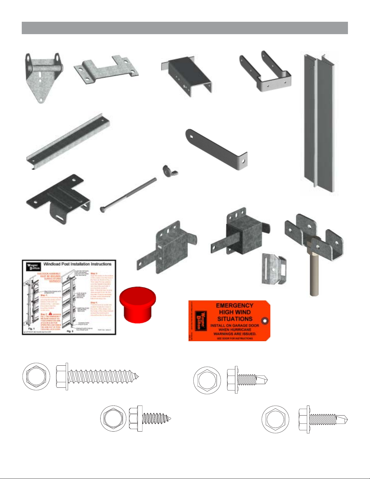
NOTE: The quantities below represent a single post for a single car garage. Double car doors require (2) posts. The
quantities for the parts below (with the exception of SLIDE LOCKS) are doubled for double car doors.
(2) HEADER LOCK
BRACKETS
# 141092
(1) HALF HINGE
# 130352
(5) STRAP BRACKETS (8’ kit
supplies (6) strap brackets)
# 305225
(1) TOP PLATE EXTENSION
# 305205
(5) J-STRUTS (8’ kit
supplies (6) J-struts)
1) 9100 # 305208
2) 9600 # 305324
3) 9900 # 305331
(4) WING NUTS (8’ kit supplies
(5) wing nuts)
# 305211
(4) CARRIAGE BOLTS
(8’ kit supplies (5)
carriage bolts)
# 305210
(1) TOP STRAP
BRACKET
# 305206
(8) STRAPS (8’ kit
supplies (10) straps)
# 305209
(1) WINDLOAD POST
7’ # 305207
8’ # 305332
(1) POST INSTALLATION DECAL
# 305213
(8) 5/16” X 1-5/8” LAG SCREW
# 100292
9100/9600 SLIDE
LOCK
# 292857
(1) PLASTIC PLUG
# 305226
9900 SLIDE
LOCK KIT
# 245773
(1) BOTTOM BRACKET
ASSEMBLY
# 305327
(1) POST TAG
# 161384
(18) 1/4-20 X 11/16” SELFDRILLING SCREW
# 300723
(12) 1/4-14 X 5/8” UNDERCUT
SELF-TAPPING SCREW
# 236565
(18) 1/4-20 X 7/8” SELFDRILLING SCREW
# 100507
2
Page 3
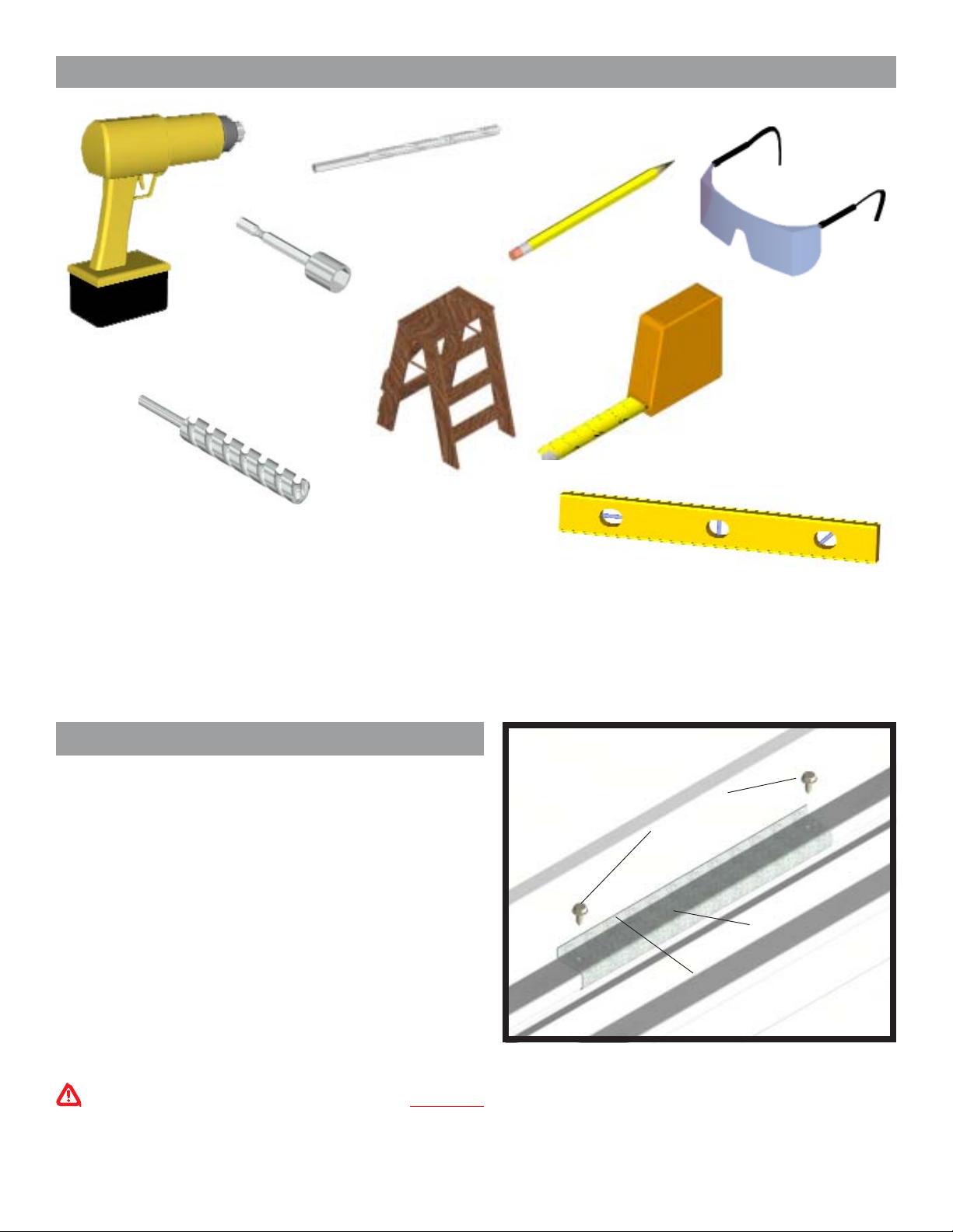
Required Tools
(1) 3/16” DRILL BIT
PENCIL
(1) 7/16” DRILL BIT
DRILL
(1) 5/8” X 4” MASONRY
DRILL BIT
STEP LADDER
Windload Post Installation
J-Strut Installation
IMPORTANT! Refer to the option code drawing
(supplied) for windload post location(s).
Place the 12” J-struts onto the lower rib of each door panel
and center over the required position per the option code
drawing. Secure J-struts using (2) 1/4-14 x 5/8” undercut
self-tapping screws. (see Fig. 1)
IMPORTANT! Specific J-struts are required for different
door models. Be sure to install the correct J-struts required
for your door.
NOTE: J-struts are stamped for identification.
SAFETY GLASSES
TAPE MEASURE
LEVEL
NOTE: J-STRUT MUST FIT ONTO THE RIB AS
SHOWN
(2) 1/4-14 X 5/8” UNDERCUT
SELF-TAPPING SCREWS
J-STRUT (MODEL
SPECIFIC)
J-STRUT IS FLUSH
AGAINST PANEL
FIG. 1
WARNING: DO NOT INSTALL THE WRONG
J-STRUTS ONTO A GARAGE DOOR, OR
WINDLOAD FAILURE WILL OCCUR.
3
Page 4

Header Lock Bracket Installation
Mark a vertical line on the header, aligned with the
center of the J-struts. Measure up 2” above the top of
the door and mark a horizontal line. Center the header
CENTER LINE
OF J-STRUT
LOCATION
2”
HEADER LOCK
BRACKET
HEADER
lock bracket with the vertical line and align the bottom
of the header lock bracket with the horizontal line.
2”
Secure the header lock bracket to the header using (4)
5/16” x 1-5/8” lag screws. (see Fig. 2)
NOTE: It is recommended that lag screws be pilot
FIG. 2
(4) 5/16” X 1-5/8”
LAG SCREWS
drilled using a 3/16” drill bit prior to fastening.
IMPORTANT! IF THERE IS DRYWALL OR OTHER MATERIALS COVERING THE HEADER IT IS
REQUIRED THAT SUCH MATERIALS BE REMOVED FROM THE HEADER LOCK BRACKET
LOCATION(S) AND REPLACED WITH THE SAME THICKNESS OF WOOD BEFORE INSTALLING
THE HEADER LOCK BRACKET(S). IF THIS PROCESS MUST BE DONE, THE LENGTH OF THE
LAG SCREWS MUST BE INCREASED TO INCLUDE THE THICKNESS OF WOOD MATERIALS SO
THAT A MINIMUM OF 1-1/2” PENETRATION INTO THE EXISTING HEADER IS OBTAINED.
Bottom Bracket Installation
Locate the bottom bracket assembly and align it to the
bottom of the post. Secure the bottom bracket to the
bottom of the windload post using (4) 1/4-20 x 11/16”
self-drilling screws. (see Fig. 3)
NOTE: The bottom of the windload post is flush while
the top is offset.
Post Hole Placement
At each windload post location, mark a center line on
(4) 1/4-20 X 11/16”
SELF-DRILLING
SCREWS
BOTTOM
BRACKET
ASSEMBLY
FIG. 3
the floor that is aligned with the center of J-struts.
Measure out from the back of the door (see Fig. 4) 6” for 9100 doors and 6-1/2” for 9600/9900 doors and make a
second mark as shown in Fig. 5. Using a masonry bit, drill (1) 5/8” x 4” deep hole into the concrete. Clean out the
hole.
IMPORTANT! FOR PROPER OPERATION OF THE WINDLOAD POST, IT IS IMPORTANT THAT
THE DIMENSION “X” BE HELD TO ASSURE
THE POST IS INSTALLED PLUMB.
DIM. X = DOOR MODEL
6” = 9100
6-1/2” = 9600
6-1/2” = 9900
CENTER LINE
OF J-STRUT
DIM. X = DOOR MODEL
6” = 9100
6-1/2” = 9600
6-1/2” = 9900
5/8” X 4”
DEEP HOLE
DIM. X
FIG. 4
DIM. X
DO NOT MEASURE
FROM BOTTOM SEAL
(SEE FIG.4)
FIG. 5
4
Page 5

Top Plate Extension Installation
Locate the top plate extension and top strap bracket. Place the top strap bracket onto the top plate extension and
adjust so that the holes in the top strap bracket align with the corresponding door model holes in the top plate
extension. Hold position and secure using (4) 1/4-20 x 7/8” self-drilling screws. (see Fig. 6)
Slide the top plate extension assembly into the header bracket.
Now, install the windload post into the post hole in the
TOP PLATE
EXTENSION
9100
9600/9900
(4) 1/4-20 X 7/8”
SELF-DRILLING
SCREWS
floor and align the top of the windload post with the top
plate extension assembly. Ensure that the post is level
and plumb.
Using (2) 1/4-20 x 7/8” self-drilling screws, secure the
windload post to the top plate extension assembly.
(see Fig. 7)
TOP PLATE
EXTENSION
ASSEMBLY
(2) 1/4-20 X 7/8”
SELF-DRILLING
SCREWS
TOP STRAP
BRACKET
FIG. 6
Strap Bracket Installation
Loosely attach (2) straps to each strap bracket using (1)
carriage bolt and wing nut (see Fig. 8). Position the
strap bracket assembly at each J-strut location and wrap
the straps around the windload post.
Ensure that the windload post is plumb while locked
into the header lock bracket and hole in floor. Secure
strap bracket assemblies to the J-struts using (2) 1/4-20
x 7/8” self-drilling screws (see Fig. 9).
Now, secure each strap to the windload post using (1)
1/4-20 x 11/16” self-drilling screw. NOTE: Keep straps
parallel and level. (see Fig. 10)
Finish hand tightening the carriage bolts and wing nuts.
STRAP
BRACKET
BOLT
FIG. 7
WING
NUT
(2) STRAP
FIG. 8
NOTE: Doors without a 3” U-bar on the top section
will require an extra J-strut and strap bracket (strap
bracket without straps) on the top rib of the top section.
(see Fig. 11)
5
Page 6

(2) 1/4-20 X 7/8” SELFDRILLING SCREWS
STRAP
STRAP
BRACKET
WINDLOAD
POST
J-STRUT
(2) 1/4-20 X 11/16” SELFDRILLING SCREWS
STRAP
BRACKET
J-STRUT
J-STRUT
FIG. 9
(2) 1/4-20 X 7/8” SELFDRILLING SCREWS
STRAP BRACKET
(WITHOUT STRAPS)
FIG. 11
Slide Lock Installation
Install slide lock on the second section of the door.
Secure the lock to the section with (4) 1/4-20 x 11/16”
self drilling screws. Square lock assembly with door
section and hole in vertical track. The slide lock should
be spaced approximately 1/8” from the section edge.
ALIGN WITH
HOLE IN
VERTICAL
TRACK
STRAP
FIG. 10
1/8”
SLIDE LOCK
IMPORTANT! SLIDE LOCKS AND OPERATORS
SHOULD NOT BE ENGAGED AT THE SAME
TIME. IF AN OPERATOR IS INSTALLED ON
THE DOOR AND ENGAGED, BE SURE SLIDE
LOCKS ARE DISENGAGED.
ONLY USE SLIDE LOCKS WHEN OPERATOR IS
DISENGAGED FROM THE GARAGE DOOR.
(4) 1/4-20 X 11/16”
SELF DRILLING
SCREWS
FIG. 12
6
Page 7

Securing Post for Storage
Locate a convenient place to store the windload post(s).
Measure and cut (2) 2 x 6” wood mounting blocks a
minimum of 10” long for each windload post. Locate
the mounting blocks horizontally on the wall as shown
in Fig. 13. Secure them adequately to the wall at the top
and bottom of the post storage location, with masonry
anchors (concrete or const.), or 12-16 penny nails (wood
const.). Measure a minimum of 6” above door as
illustrated, and mount the extra header lock bracket(s)
to the top mounting block(s) using (2) 5/16” x 1-5/8”
lag screws as shown in Fig. 13.
(2) 5/16” X 1-1/2”
LAG SCREWS
6” MIN.
HEADER LOCK
BRACKET
Measure the distance from the top of the windload post
to the center of the bottom strap (see Fig. 14). Use that
measurement for the displacement between the center
of the extra header lock bracket and half-hinge tube.
Position the half-hinge on the bottom mounting block
and secure the half-hinge using (2) 5/16” x 1-5/8” lag
screws. Repeat this step for remaining windload posts
if necessary. (see Fig. 13)
Slide the windload post(s) into storage header bracket(s)
and secure the bottom strap(s) to the half hinge(s) using
the wing nut and carriage bolt. Place all remaining wing
nuts and carriage bolts into the remaining straps for
storage. Insert plastic plug into hole in floor.
TOP OF WINDLOAD POST
DISTANCE BETWEEN TOP
OF WINDLOAD POST AND
CENTER OF BOTTOM
STRAP
(2) 5/16” X 1-1/2”
LAG SCREWS
TUBE
HALF-HINGE
FIG. 13
Rebalance The Door
Now that the windload post is NOT installed onto the door,
check the door’s balance, by manually opening and
closing the door. The door may be heavy because of the
extra hardware added. To accommodate the extra weight,
tension must be added to the counterbalance springs.
See chart for adding spring tension.
TOP OF THE WINDLOAD
POST TO THE CENTER
OF THE BOTTOM STRAP
BOTTOM
STRAP
BOTTOM OF WINDLOAD POST
FIG. 14
ecnalabretnuoC
metsyS
™retsaMeuqroTnrut2/1
gnirpSnoisroTnrut2/1
MEASURE THE
DISTANCE FROM THE
otdeddAsnruTforebmuN
metsySecnalabretnuoC
NOTE: Refer to the garage door’s main installation
instructions and owner’s manual for instructions on
adding/removing spring tension.
gnirpSnoisnetxEtnemecalpkooh"S"etacoleR
7
Page 8

Attaching the Installation Decals
After the installation is complete, locate an easily visible location on the inside of the garage door and the post(s)
and place the provided installation decals onto the door and post(s) for future reference.
IMPORTANT! DECALS MUST BE ATTACHED TO BOTH DOOR AND POST(S).
MAKE SURE A DECAL LIKE THE FIGURE ABOVE IS
INSTALLED ON THE DOOR!
CONTACT WAYNE-DALTON CORPORATION
FOR A REPLACEMENT DECAL.
8
Page 9

Windload Label Locations
2
1
3
1
2
3
Applied by Installer - One (1) Emergency High Wind Situations Tags
(161384) per post -Tags are to be applied to post(s) when stored on
wall for constant reminder to consumer.
Applied by Installer - One (1) Windload PSF Label per post, based on
the required design PSF load. Label is to be applied to windload post
for reference.
Applied by Installer - One (1) Florida Windload Installation Label (305213)
-Only on doors specified with one or more posts. To be applied next to
endcap of second section on side of opening where Post no. 1 is stored.
9
 Loading...