

Page 1
L3-LL Multimaximizer™
User Manual
Page 2

L3-LL User Manual
2
Page 3

L3-LL User Manual
TABLE OF CONTENTS
CHAPTER 1 – INTRODUCTION...........................................................................................................................................4
1.1 WELCOME ..........................................................................................................................................................................4
1.2 PRODUCT OVERVIEW .........................................................................................................................................................5
1.3 CONCEPTS AND TERMINOLOGY ..........................................................................................................................................7
The Peak Limiting Mixer™.................................................................................................................................................7
Gain and Priority................................................................................................................................................................7
Separation...........................................................................................................................................................................7
L3-LL Release Behavior......................................................................................................................................................8
1.4 COMPONENTS.....................................................................................................................................................................8
CHAPTER 2 – QUICKSTART GUIDE..................................................................................................................................9
CHAPTER 3 – CONTROLS AND INTERFACE.................................................................................................................10
3.1 GLOBAL LIMITER SECTION...............................................................................................................................................10
3.2 GRAPH DISPLAY AND CONTROLS SECTION.......................................................................................................................13
Main Display.....................................................................................................................................................................14
Band Controls...................................................................................................................................................................15
3.3 IDR™ SECTION ................................................................................................................................................................18
CHAPTER 4 – THE WAVESYSTEM...................................................................................................................................19
4.1 THE WAVESYSTEM TOOLBAR ..........................................................................................................................................19
Toolbar Functions.............................................................................................................................................................19
4.2 PRESET HANDLING...........................................................................................................................................................19
Preset Types......................................................................................................................................................................19
Loading Presets and Setups..............................................................................................................................................20
Saving Presets and Setups.................................................................................................................................................20
Deleting Presets................................................................................................................................................................21
A/B Comparison and Copying ..........................................................................................................................................21
4.3 INTERFACE CONTROLS .....................................................................................................................................................21
Toggle Buttons..................................................................................................................................................................21
Value Window Buttons......................................................................................................................................................22
Faders...............................................................................................................................................................................22
Band Markers....................................................................................................................................................................22
Multiple Selection of Controls ..........................................................................................................................................23
TAB Functions ..................................................................................................................................................................23
APPENDIX A – CONTROLS LIST.......................................................................................................................................24
APPENDIX B - IDR™ IN DEPTH.........................................................................................................................................25
Dithering and Noise Shaping............................................................................................................................................25
IDR™ Dither Options........................................................................................................................................................25
IDR™ Noise Shaping Options...........................................................................................................................................26
3
Page 4

L3-LL User Manual
Chapter 1 – Introduction
1.1 Welcome
Thank you for choosing Waves! In order to get the most out of your Waves processor, please take the
time to read through this manual.
In conjunct
an extensive Answer Base, the latest Tech Specs, detailed Installation guides, new Software
Updates, and current information on Authorization and Registration.
By signing up at www.wavesupport.net
products, reminders when updates are available, and information on your authorization status.
ion, we also suggest that you become familiar with www.wavesupport.net
, you will receive personalized information on your registered
. There you will find
4
Page 5
1.2 Product Overview
L3-LL User Manual
The Waves L3-LL Multimaximizer is a Low Latency 5-band auto-summing peak limiter, the fifth
processor in
Multimaximizer, Waves revolutionized the world of mastering. For the first time, producers and
engineers could shape their final mixes with unprecedented precision. Now, Waves is proud to present
the L3-LL, a multiband peak limiter that lets you maximize your mix, track by track, instrument by
instrument.
Powered by the Waves PLMixer™
Release controls arranged in a 5 band interface. The L3-LL features a phase-compensated crossover
network that splits the signal into 5 adjustable frequency bands while maintaining minimal phase
distortion.
The L3-LL uses the same Profiles presets as its predecessor the L3, offering a wide variety of sonic
flavors ranging from analog warm to
ARC™ Automatic Release Control across the split-band spectrum.
Waves’ acclaimed L-Series of Ultra
Peak Limiting
digital coo
maximizers and Multimaximizers. With the L3
Mixer engine, the L3-LL offers Gain, Priority and
l. Release Characters affect the behavior of the L3-LL’s
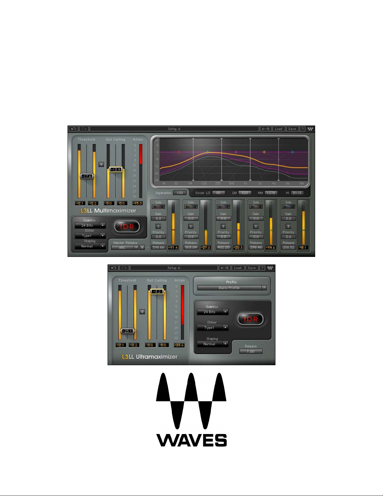
The L3-LL offers two different plug-in interfaces to control the same essential algorithm.
The L3-LL Ultramaximizer maintains the general control surface of its predecessors the L1 and L2.
It adds a Pr
The L3-LL Multimaximizer allows full parametric control over Gain, Priority and Release factors for
each freque
limiting; it can be used as a fully self-contained mastering chain.
ofile selection that controls different internal settings of the multiband engine.
ncy band, for equalization and fine tuning. In fact, the L3-LL offers much more than just
5
Page 6

Finally, the L3-LL features Waves IDR™ Increased Digital
quantization and 9
th
-order noise shaping, for enhanced audio resolution at any setting.
Resolution d
L3-LL User Manual
ouble precision bit re-
6
Page 7
L3-LL User Manual
A
1.3 Concepts and Terminology
The Peak Limiting Mixer™
Traditional multiband limiters consist of a given number of limiters operating independently of each
other, each set to a particular frequency range. The key to the L3-LL’s power is its patent-pending
PLMixer™ Peak Limiting Mixer engi
Dividing the audio spectrum into 5 bands using phase-compensated crossover filters, the PLMixer™
uses psychoacoustic crit
all available headroom. The PLMixer™ incorporates superimposed Gain and Priority control that allow
the user to set gain and priority (relative limiting) across the audio spectrum, functioning like an EQ
before the L3-LL’s limiting section. The result is that inter-modulation distortion is minimized and overall
loudness is maximized, while retaining the simplicity of a single master threshold control.
Unlike traditional multiband limiters, the PLMixer™ does not require a wide band peak limiter to catch
overshoots generated by individual band adjust
between bands while maintaining brickwall limiting.
eria to intelligently decide how much attenuation to apply to each band, using
Gain and Priority
The L3-LL’s Gain curve and Priority control make for a very powerful mastering tool, enabling both
equalization and multiband limiting. The 5-band phase-compensated crossover engine is controlled by
4 frequency cutoff controls.
ne, which uses a single peak limiter to control all of its bands.
ments; it automatically controls the gain relationship
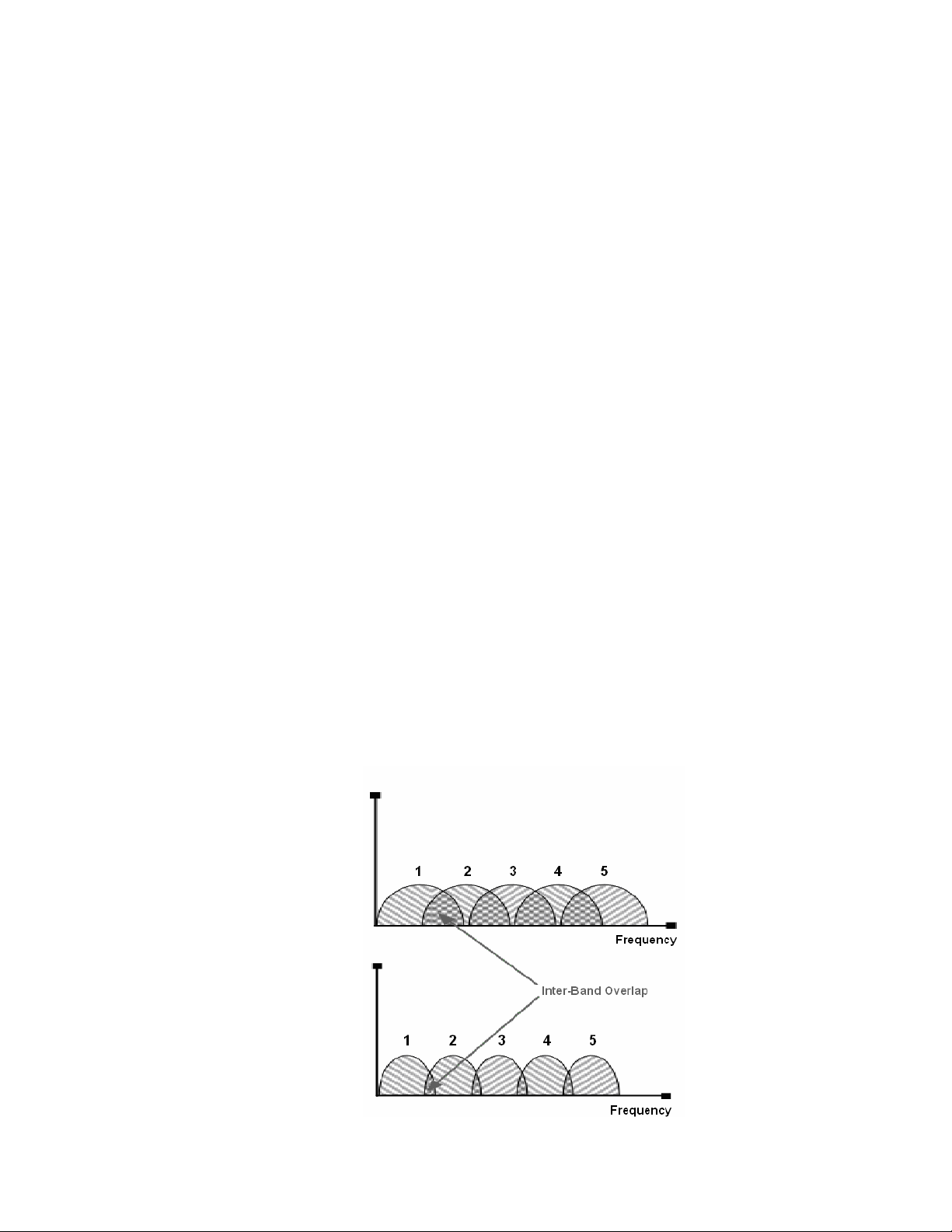
Separation
The L3-LL phase-compensated crossover allows control over the amount of Separation between its 5
bands. Separation is similar to a filter cutoff slope (or Q) between the bands’ sidechain being fed to the
PLMixer™. At low Separation settings, crossover slopes between bands are moderate, creating more
overlap between the bands. At higher Separation settings, the crossover slopes are steeper, resulting
in less overlap between the bands.
A. Frequency bands’
Side-Chain at low
Separation value
B. Frequency bands’
Side-Chain at high
Separation value
B
7
Page 8

L3-LL User Manual
L3-LL Release Behavior
The L3-LL offers a wide range of sound qualities which are controlled using the release settings across
its frequency bands.
Like its predecessor the L3, the L3-LL’s band release times are determined by Waves ARC™ Auto
Release Control, which dynamically chooses the optimal release value for a wide range of inputs. The
ARC™ system, like the human ear, analyzes and reacts to RMS and peak transients differently,
resulting in increased RMS level with greater clarity.
While ARC™ is always engaged, the L3-LL Multimaximizer allows independent release controls for
each frequency band along with a global Master Release preset control. For example, a Master
Release preset could consist of relatively fast release values for the low frequency bands, with
gradually slower release values for the higher frequencies. Accordingly, this character would apply
more attenuation to the higher frequency range.
The L3-LL Ultramaximizer has Profiles that contain per band settings for Priority, Release, and
Separation, together with a global Release control that proportionately shortens or lengthens each
band’s release values.
We highly suggest that you experiment with the various Release parameters in order to discover the
wide range of sonic flavors the L3-LL can achieve.
1.4 Components
WaveShell technology enables us to split Waves processors into smaller plug-ins, which we call
components. Having a choice of components for a particular processor gives you the flexibility to
choose a configuration suitable for your material.
The L3-LL has two component processors:
L3-LL Multimaximizer Stereo - A stereo channel processor with individual band control.
L3-LL Multimaximizer Mono – A mono channel processor with individual band control.
L3-LL Ultramaximizer Stereo - A stereo channel processor with global band control.
L3-LL Ultramaximizer Mono – A mono channel processor with global band control.
8
Page 9

Chapter 2 – Quickstart Guide
L3-LL User Manual
We recommend reading this manual to get the most out of the L3-LL. However, for a quick start to
setting up the L3-LL on
1. Insert the L3-LL Multimaximizer into your project, preferably as the last processor on the m
buss with no
2. Play your audio, selecting a loop with a high RMS level.
3. Select the Threshold/Out Ceiling Link control,
and drag downward while watching t
4. Once the Attenuation meter registers gain reduction, listen carefully and continue to
downward until you hear degradation, distortion, or a reduction in level.
6. Set the Out Ceiling control to -0.2dBfs.
Set the IDR
7.
8. Process your audio.
your audio, follow these st
subsequent
Quantize factor to match your designated medium.
gain adjustment.
eps:
located between the Input and Output meters,
he Attenuation meter.
da5. At this point, stop, and drag upward until the output sound is free of such degra
drag
tions.
aster
9
Page 10

L3-LL User Manual
Chapter 3 – Controls and Inte
Global Limiter
Section
IDR Section
3.1 Global Limiter Section
rface
Frequency
Bands
Controls
and Graph
Section
Thi
s section consists of controls that globally affect all of the L3-LL’s bands.
Th
reshold/Input Meter
- Range -30dB to 0dB
- Default 0dB
Threshold is probably the most important control of the L3-LL, as it sets the global limiting threshold as
a reference threshold for the 5 bands. Once set, any signal that goes above the threshold is limited,
and gain is automatically made up by the same factor; i.e., if Threshold is set to -6dB, then automatic
makeup gain will accordingly be 6dB.
The Threshold fader is located on the Input Meter, allowing easy adjustment with reference to input
energy. Below the Input Meter, you will find Waves standard peak indicators. Click the peak indicator
field to reset.
10
Page 11

L3-LL User Manual
ut Ceiling/Output Meter O
-
Range -30dB to 0dB
- Default 0dB
The Out Ceiling fader sets maximum output level, scaling the output signal to reach the out ceiling
value but not exceed it.
The Out Ceiling fader is located on the Output Meter. Below the Output Meter are Waves standard
peak indicators. Click the peak indicator field to reset.
Threshold/Out Ceiling Link
The
threshold setting changes while monitoring the limiter effect without its makeup gain action.
button lets you adjust the Threshold and the Out Ceiling faders simultaneously, allowing
Attenuation Meter
- Range -30dB to 0dB
T
he Attenuation Meter displays the overall (wideband) attenuation.
Ultramaximizer Profiles
-Range
Basic Profile
Extreme Analog
Semi Separated
WideBand ARC
WideBand Manual
Loud & Proud
- Default
The Profiles drop down menu contains factory settings for the L3-LL Ultramaximizer internal frequency
bands controls. Each Pr
only available in the L3-Multimaximizer.
Cosy & Warm
Lean & Mean
Low Level Loudness
Basic P
rofile
ofile contains per band Priority, Release, and Separation settings, otherwise
11
Page 12

L3-LL User Manual
Ultramaximizer Relea
se
- Range x0.1 to x10.0
- Default x1.0
The Release value is a multiplier for the L3-LLUltramximizer’s internal release time constants, as se
the selected
sult in shorter release times; higher values result in longer release times. re
Profile. It pr
oportionately shortens or lengt
hens each band’s release values; lower values
t by
12
Page 13

.2 Graph Display and Controls Section
3
L3-LL User Manual
This section consist
Release, and Master Release.
s of the main display and controls for Separation, Xover, Solo, Gain, Priority,
Gain and Priority can be adjusted independently, or together, using the Link control. All parameter
settings can be controlled by direct numerical entry into value windows, or by using the graphic display
band markers.
To use these controls effectively, you need some understanding of the L3-LL’s internal logic. Like a
wideband limiter, the L3-LL applies attenuation only when the threshold is exceeded; unlike a wideband
limiter, it does not apply the same amount of attenuation over the whole spectrum. Rather, it applies
more attenuation to bands that contain signals with higher peaks. This creates less inter-modulation
distortion, and retains more detail from the input signal.
Raising a band’s Gain against the limiter’s threshold results in more limiting being applied to that band.
Priority allows you to control the amount of limiting applied to each band. Higher Priority results in less
limiting (in relation to other bands), while lower Priority results in more limiting. Typically, Gain and
Priority controls are adjusted together using the Link control, so that the Priority creates the necessary
headroom for Gain to take place. However, it’s important to note that controlling the Gain and Priority
separately can actually lead to very interesting and widely diverse sonic results.
13
Page 14

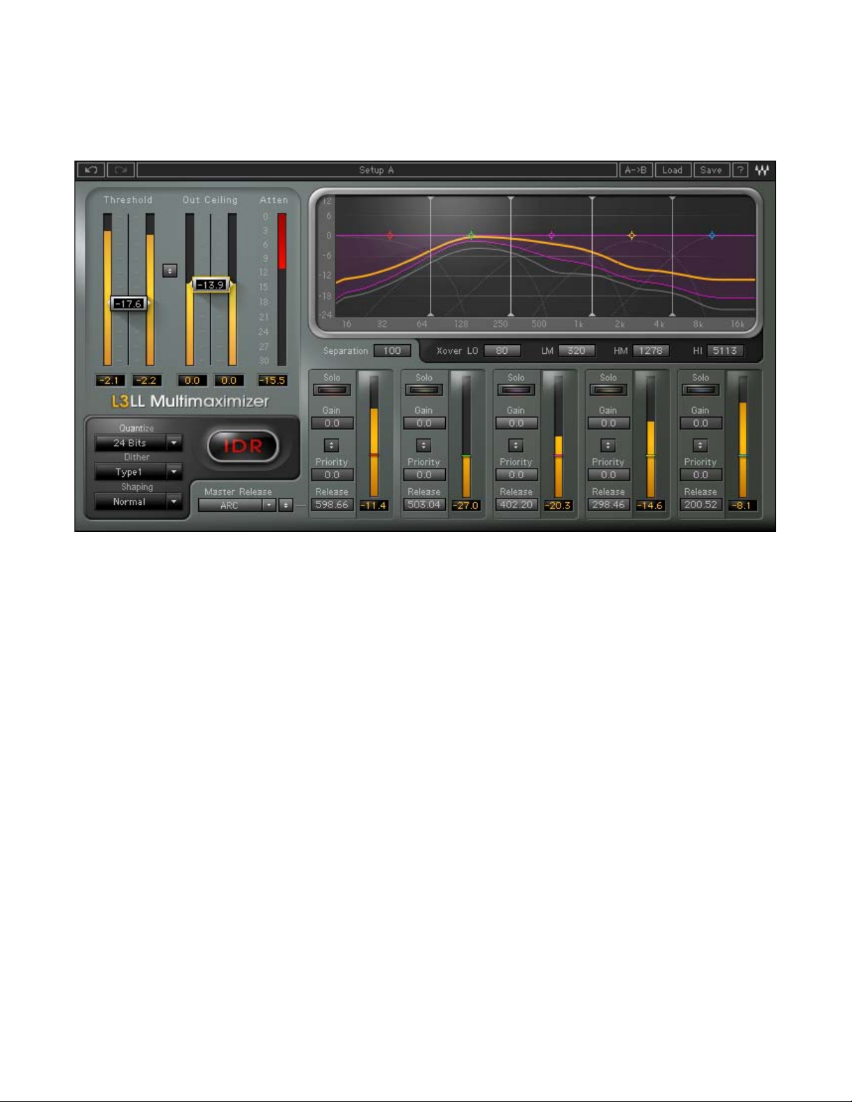
Main Display
r
L3-LL User Manual
Gain
Curve
Frequency
Band Marker
Crossover
Cutoff Marke
Peak Attenuation
Hold Curve
Attenuation
Range
Dynamic Gain Line
Momentary Attenuation
The Gain/Frequency graph displays the peak attenuation across the frequency range.
The top purple line is the applied Gain curve.
The orange line is the Dynamic Gain line and shows Gain changes as they happen.
The semi-transparent purple shade displays a smoothed trail of the Dynamic Gain line.
The lower gray line is the Dynamic Gain peak hold which displays the maximum attenuation
across the frequency spectrum.
The graph also includes 5 mark
m
oved up or down, adjust the linked Gain and Priority.
The graph also has 4
line markers that display and allow adjustment of the crossover frequencies.
ers which, when moved left or right, adjust the bands’ width, and when
C
lick-vertical drag the band markers changes gain and priority
Click-horizontal drag the band markers changes frequency bandwidth
Control-click
Command-click (Mac) and drag constrains movement to the X o
(PC)/
axis – vertical drag will lock frequency but allow gain change, and horizontal drag will
lock gain but allow frequency change
Alt-click (PC)/Option-click (Mac) and horizontal drag allows Q adjustment, and
disables the vertical axis while held
Double click on any band marker to toggle in or out
Shift-click to select multiple band markers for simultaneous control; sh
ift-click again on
any marker you wish to de-select
r Y
14
Page 15

L3-LL User Manual
Band Controls
T
he Band Controls section features controls over the Crossover network which splits the input into
Frequency Bands. Each Band has controls for Solo, Gain, Priority, Release, and a Mete
in
put level.
r displaying the
Se r
pa ation
- R g
an e 0 to 100
- Defau
lt 100
Separation is similar to a filter cutoff slope (or Q) between the bands’ sidechain being fed to the
PLMixer™. At low Separation settings, crossover slopes between bands are moderate, creating more
overlap between the bands. At higher Separation settings,
less overlap between the bands.
in
the crossover slopes are steeper, resultin
g
Crossove
Just below t
L3-LL. Eac e
Each of the
LOW Range:
O MID Range: 150Hz to 300Hz. Default to 320Hz.
LHW
I MID Range: 1000Hz to 5000Hz. Default to 1278Hz.
I Range: 3kHz to 11kHz. Default to 5113Hz.
H
er Band Solo
P
Solo the frequency band to adjust the frequency bandwidth. Solo outputs the signal post the crossovers
and pre the dynamic process.
r (Xover) Controls
he graph are the Crossover frequency adjustment controls. There are 4 Crossovers in the
h s ts the cutoff frequencies for the corresponding High Pass and Low Pass filters.
four Crossovers has a unique range of frequencies, as follows:
20Hz to 350Hz. Default to 80Hz.
15
Page 16

L3-LL User Manual
Gain
- Range -12dB to +1
-
Default 0dB
Gain controls the overall gain of each frequency band. To boost the gain of a given range without overlimiting it, raise both Priority and Gain.
2dB
Gain/Priority Link
The
them.
button allows simultaneous control of Gain and Priority, retaining a constant offset between
Priority
- Range -12dB to +12dB
- Default 0dB
P
riority adjusts the relative limiting, or relative attenuation distribution, across the bands. Raising
P
riority applies less attenuation to the respective bands (in relation to other bands) while maintaining
the same over
It’s important to rem
bands are set t
all limiting; lowering Priority results in more attenuation applied to the respective bands.
ember that Priority settings are RELATIVE between bands. This means that if all
o the same non-zero priority, it has the same effect as setting all priorities to 0.
Priority Indicators
- Range -12dB to +12dB
- Default 0dB
The
displays the applied priority for the frequency band.
Per Band Release
- Range 0.1 to 2500.
The per band Release sets the reference Release time for each band. This reference
be further adjusted by the Master Release Beha
vior type.
release time can
Master Release Link
The
16
button allows relative release adjustment for all bands.
Page 17

L3-LL User Manual
Maste
- Range ARC, Aggressive,
- Default ARC
Waves ARC™ Auto Release Control technology optimizes the actual release time in context with the
program. In the L3-LL all Release beha
a
ARC – This is the nom
W
Scaled
Aggressive
s
r Release
Warm, Scaled, Manual
vior types use a certain amount of ARC, where some are more
daptive and others less, or the amount of ARC is scaled across the bands in different ways.
inal default release behavior type. It is a good overall setting for most material.
arm – Applies more ARC processing to low frequency bands, less on high frequencies.
– Applies more ARC processing to high frequency bands, less on low frequencies..
– Delivers most overall loudness o
anuaM
l – Applies minimal ARC processing. Each band’s release time will correspond to its Release
etting.
n transient-rich material.
17
Page 18

L3-LL User Manual
3.3 IDR™ Section
uantizQ e
Range 24, 22, 20, 18, 16 bit
-
- Default 24
The Quantize control sets the target bit depth of the L3-LL output. Quantize is always active, so the
output of the L3-LL will be quantized to a maximum of 24-bits even if you are in a floating point
environment.
Dither
- Range Type 1, Type 2, None
- Default Type 1
Type 1 is “purist” dithering, designed for no modulation noise at low levels. IDR™ Type 1 is optimized
for use at every processing stage, allowing for the effects of cascading and subsequent signal
processing. Type 1 is also optimized to generate minimal side effects when used with stereo signals.
Type 2 is designed to minimize the amount of added noise. It delivers a lower noise level than Type 1
at the expense of some low level distortion. Type2 is "auto-muting" with no input signal is present.
Shaping
- Range Normal, Moderate, Ultra, None
- Default Normal
The Shaping control selects the type of noise shaping filter that will be applied to the dither and/or
quantization noise. Noise shaping transfers the noise energy toward the higher, less audible range of
the frequency spectrum. Selecting None leaves the noise unfiltered.
IDR Active Indicator
Whenever Dither or Noise Shaping are engaged, the IDR status indicator
activity in the IDR section. When both Type and Shaping are set to None, the IDR logo will turn gray to
indicate that IDR is disengaged. The output is still rounded according to the Quantize bit depth chosen.
18
will be colored red to indicate
Page 19

L3-LL User Manual
Chapter 4 – The
WaveSystem
4.1 The WaveSystem Toolbar
All Waves processors fe
functions you will encounter while working with your Waves software. The features of the WaveSystem
toolbar are the same on practically all Waves processors, so familiarity with its features will be helpful
whichever processor you are using.
Toolbar F
Undo
edo
Setup A/B Toggles bet
Copy A->B Copies the current settings to the second preset register
oad L
ave Saves presets in the Waves file formats
S
?
unctions
R
Undoes the last
Redoes the last undone action
settings
Recalls presets from file
Opens the manual for the processor you are using
ature the WaveSystem toolbar which takes care of most administrative
performed action. The L3-LL supports multiple undo levels.
ween two presets. This is useful for close comparison of different paramet
er
4.2 Preset Ha
ndling
Preset Types
F
actory Presets are permanent presets in the Load menu. Factory presets cannot be over-written or
deleted. When applicable, different component plug-ins may have different factory presets.
U
ser Presets are your favorite settings of the plug-in saved as a preset in the Load menu, under ‘User
P
resets’. User Presets can be over-written and deleted.
Setup Files may contain more than one
a session. When y
a
ccess. This can be particularly useful with multiple instances of a plug-in in a single session. By saving
all the settings you create into a single Setup File, they can all be quickly available for every instanc
that plug-in.
ou open a Setup File, all its setups become part of your Load pop-up menu for fast
preset. For example, a single file can contain all the presets for
e of
19
Page 20

L3-LL User Manual
Loading Presets and Setups
Click-and-hold on the Load button to see the Load pop-up menu. The menu is divided into four
s
ections. If a section
Open Prese
‘Filename.xps’: Displays any c
Factory Presets: Displays the default Factory Presets.
User Presets: Di
t File…
is not currently available it will not appear in the Load pop-up menu.
Select to open any setup or preset file, whether from the Library or your own
creations.
urrently loaded Setup File and its presets.
splays any loaded User Presets.
es
ave pop-up menu. Fock-and-hold ur options are available. If an
Select this to start a new Setup file. There are two prompts - first
for the setup filename, then for the preset name. You must provide
a name for both the setup file and the preset. Click OK (ENTER)
to complete the save. It is a good idea to create a folder in which
to save several setup files for a project.
” Overwrites the settings
Preset or a preset from a Setup File) with the current se
Setup File is currently loaded, the name of the Setup File is
displayed followed by the name of the preset itse
Preset is loa
Saves the current settin
is open (if one is not open, the option is grayed out). You will be
prompted to give the preset a name.
your Load menu (until deleted). You will be prompted to give this
preset a name. User Presets are stored in the plug-in’s preference
file.
ded, its
of the loaded preset (whether a User
ttings. If a
lf. If a User
name is displayed.
gs as a new preset into the Setup file that
Saving Pr ets and Setups
Cli on the Save button to see the S
ption is not currently available it will be grayed out and inaccessible.
o
Save to New File…
Save ‘File Name’ – “Preset Name
Save to ‘File Name’ As…
Put into Preset Menu As… Save the current settings into a User Preset that will always be in
20
Page 21

L3-LL User Manual
Deleting Presets
You may delete User Presets and presets within a Setup File. Factory Presets and Setup Library files
cannot be leted or overwritten.
1. Hold the Command (Mac)/Control (PC) key down.
2. Click-and
3. While still holding the Command/Control key, select the preset or setup to delete.
4. A confirmation box will appear, allowing you to cancel or
de
-hold the Lo
ad button to see the pop-up menu.
‘OK’ the deletion.
A/B Comparis and Copying o
The Setup A/Setup B button may be clicked to compare two settings. If you load a preset in the Setup B
position, this will not affect the prese
If you want to slightly modify the settings in Setup
Copy to B tton, then alter Setup A and compare with the original Setup B.
The name of the current setup will be shown in the title bar (on platforms which support it), and will
switch as yo
Note: an asterisk will preset name when a change is made to the preset -
bu
u change fro
n
m Setup A to Setup B.
be added to the
t loaded into
the Setup A position, and vice-versa.
A, you can copy them to Setup B by clicking on the
4.3 Interface Controls
Controls can be in one
• Not Selected where the cont
• Selected where the control is
• Selected and Activ he control is the tar
of three states:
rol is
the target of mouse control entry only
e where t
not the target of any user entry
get for both mouse and keyboard entry
Toggle Buttons
Toggle buttons display the state of a
click to change the control’s state. Some toggle buttons have a text display which updates with the
current setting, and others (bypass, solo, or monitoring toggles) illuminate when the control is active.
Some processors have link buttons between a pair of toggle buttons, allowing click-and-drag
adjustment while retaining the offset between the controls.
21
control, and allow switching between two or more states. Single-
Page 22

L3-LL User Manual
Value Window Bu
Value windows display the value of a control and allow click-and-drag
via the keyboard.
• Using the mouse, click-and-drag on the value
left/right, so
direction of movement that button supports).
• Using the arrow
left/right (depending on the direction supported by that button) to move in the smallest
incremental steps across the bu
through the range).
• Using key entry, double click on the button to open the value window, and directly enter the
value from your keyboard. If you enter an out of range number, the button stays selected but
remains at the current setting (system beeps? If system sounds are on?)
Some processors have link buttons between a pair of value windows, allowing click-
adjustment while retaining the offset between the controls.
ttons
window to adjust. Some value windows support
me up/down (as you hover over a button
s, click once with mouse to select the button, and
key
tton’s range (holding down the arrow keys will move faster
adjustment, or direct control
, arrows will appear to let you know which
then use up/down –
and
-drag
Faders
lick on the fader itself or anywhere within the faC
displayed in a window above the slider path. When pairs of faders are provided for stereo c
uch as in t
(s
offset between them if there is some)
he Q10) click-and-drag between the faders will adjust both faders together (maintaining any
der track. The numerical value of the slider settings is
ontrols
Band Markers
an m tions:
B d arkers appear on all Waves graphic displays, and have many func
•
Click-vertical drag changes gain.
•
Click-horizontal drag changes frequency.
•
Click- diagonal drag will adjust gain and frequency together.
Control-clic
•
axis – vertica
but allow frequency change.
•
Alt-click (PC)/Option-click (Mac) and horizontal drag allows Q adjustment.
Shift-click to select multiple band markers for simultaneous control, and shift-click again on
•
any marker you wish to de-select.
Double click (PC) /Command-click (Mac) on any band marker to toggle in or out.
•
Drag on any de-activated band marker to re-activate it.
•
•
Option/Command-click (Mac only, not supported on PC) to change filter type.
22
k (PC)/Command-click (Mac) and drag constrains movement to the X or Y
l drag will lock frequency but allow gain change, and horizontal drag will lock gain
Page 23

L3-LL User Manual
Multiple Selection of Co
One of the most powerful features of the WaveSystem is the ability to select and adjust many controls
at the same time. Us
b
y clicking and holding at a point outside the controls and forming a rectangle to include the controls
w h to adjust. Alternatively, you can hold down Shift while clicking th
you is
wish to
separa h to select.
TAB F
moves the ‘selected’ status to the next control, with shift-TAB moving in the reverse direction.
TAB
Additio ption-TAB for ‘up’
ovement where applicable.
m
If you have
ontrols only.
c
This second method is useful when you want to select two (or more) controls that are
link.
ted on the GUI by other controls you do not wis
unctions
nally, the Mac has an option-TAB function for ‘down’ movement and shift-o
several Value Window Buttons sele
ing the mouse, simply drag-select the desired group of button or graphic controls
ntrols
cted, TAB fu
e mouse on any control you
nctions will take you through the selected
23
Page 24

Control Range Default
Threshold/Input Meter
Out Ceiling/Output Meter
Attenuation Meter
Master Release
Release
Priority
Gain
Xover
Separation
Quantize
Dither
Shaping
Ultramaximizer Profiles
Ultramaximizer Release
L3-LL User Manual
st Appendix A – Controls Li
-30dB to 0dB 0dB
-30dB to 0dB 0dB
-30dB to 0dB
ARC, Aggressive, Warm,
Scaled, Manual
0.1ms to 2500ms 598ms, 503ms, 402ms, 298ms, 200ms
-12dB to +12dB 0dB
-12dB to +12dB 0dB
LO = 20Hz to 350Hz
LM = 150Hz to 3000Hz
HM = 1000Hz to 5000Hz
HI = 3000Hz to 1100Hz
0 to 100 100
24, 22, 20, 18, 16 bit 24bit
Type 1, Type 2, None Type 1
Normal, Moderate, Ultra, None Normal
Basic Profile
Extreme Analog
Semi Separated
WideBand ARC
WideBand Manual
Warm & Cosy
Loud & Proud
Lean & Mean
Low Level Loudness
x0.1 to x10.0 x1.0
ARC
LO = 80Hz
LM = 320Hz
HM = 1278
HI = 5113Hz
Basic Profile
Hz
24
Page 25

L3-LL User Manual
Appendix B - IDR™ In Depth
Dithering and Noise Shaping
Dithering and Noise Shap dependent, com t imp
perceived quality of digital a has been re-qu respo
improvement of a dif
Dithering alters the character of the qu more closely resemble analog hiss, rather
than digita ain effect of ditheri reduce or eliminate all correlation
between e original signal, t ear d
typical e dithering proces distor
steadie ss type noise.
Noise Shaping psycho-acoustical of overall noise energy across the
spectrum, by taking into account th hich the ear is mo ise
Shaping dec kHz range nsitiv
increasing s sens
In short, d aping work by modifying the ch
Here’s how Dithering and Noise Shaping help maintain 3 more bits of detail: Our brains are capable of
perceiving details that are lower than the noise floor. Since quantization noise is correlated to the
signal, it effectively masks the signal is correlation by inserting random signals,
allowing our brain to distinguish signal from noise and thus perceive low level details. Noise shaping
adds even more detail by shifting noise le range, away from the desired signal.
l quantization noise. The m ng is to
the quantization noise and th hus minimizing the non-lin istortion effects
of digital quantization noise. Th s replaces the non-linear tion sound with
r, less displeasing analog-hi
reases noise level in the 1-6 , a range to which the ear is se e, while
noise level in the frequency range above 15 kHz to which the ear is les itive.
ithering and noise sh aracter and frequency content of noise,
ing are two in plementary techniques tha rove the
udio after it antized. Each technique is nsible for the
ferent subjective quality of the noise caused by re-quantization.
antization noise to
ly optimizes the distribution
e frequency ranges to w st sensitive. No
to ou
r ears. making it less displeasing
. Dithering breaks th
to a less audib
IDR™ Dither Options
ype1
T
ype 1 is a wide-band dither. Type1 adds a certain amount of noise, causing a 5dB increase in
T
ackground noise. It completely eliminates low-level distortion and signal-dependent modulation
b
effects. The result is a very transparent and clean low-level sound with a high resolution. It most
resembles the steady low-level hiss of an excellent quality analog system with no digital quantization
noise.
Type1 delivers no nonlinear distortion or modulation noise at low levels, and generates minimal side
effects when used with stereo signals. It is the recommended choice for high quality mastering
applications. By combining level maximization and IDR™ processing, 16-bit audio created from 20 or
24-bit masters have an apparent resolution of 19 bits. This is an improvement of more than 18dB.
Finally, unlike other dithering engines that are designed for single-stage CD mastering, IDR™ Type 1 is
optimized for use at every processing stage, allowing for subsequent signal processing.
25
Page 26

L3-LL User Manual
Type2
Type 2 is a narrow-band dither which adds a m
about 5dB lower than Type 1, while adding so
when no dithering is applied.)
inimal the amount of noise. It delivers a noise level
me low level distortion. (The distortion level is lower than
IDR™ Noise Shaping Options
As explained above, noise shaping shifts the noise to the frequency ranges where we hear it the least.
he three Noise Shaping options provided by the IDR™ system differ in the amount of this shT
IDR™ features ninth-order Noise Shaping filter for optimal sound quality.
Moderate
This setting typically reduces perceived hiss (or distortion, if dither is not used) by around 6dB. The
added high frequency noise is about 9dB at 44.1 k
Hz sampling rate.
Normal
This setting typically reduces perceived hiss (or distortion, if dither is not used) by around 12dB. T
added high frequency noise is about 15dB at 44.1 kHz sampling rate. This setting, together with T
dithering, is well suited to the creation of CD production masters. It is also good for masters tha
p
rocessed again for any reason, including consecutive re-dithering, as its accumulated noise effect is
minimal.
ltra
U
This setting delivers the greatest perceived hiss/distortion reduction, typically around 18dB. The added
high frequency noise is about 23dB at 44.1 kHz sampling rate. This setting is suitable only at the v
last stage of mastering high resolution audio for high-quality digital media (16-bit and longer
wordlengths). Ultra is best suited for the final stage of preparing production masters, and should be
avoided in cases where the audio will undergo further editing.
Here are
some recommended IDR™ settings:
• For CD-mastering, Type 1 dithering with Normal noise shaping
For minimum noise, Type2 dithering with Ultra noise shaping
•
• For maximum resolution, Type1 dithering with Ultra noise shaping
ifting.
he
ype1
t may be
ery
26
 Loading...