

Page 1
WAVES
KRAMER MASTER TAPE
USER GUIDE
Page 2

TABLE OF CONTENTS
CHAPTER 1 – INTRODUCTION ......................................................................................3
WELCOME .................................................................................................................3
1.1
PRODUCT OVERVIEW.................................................................................................3
1.2
CONCEPTS AND TERMINOLOGY ..................................................................................4
1.3
1.4
COMPONENTS ...........................................................................................................7
CHAPTER 2 – QUICK START GUID
E.............................................................................8
CHAPTER 3 – INTERFACE AND CONTROLS ...............................................................9
INTERFACE ................................................................................................................9
3.1
CONTROLS ..............................................................................................................10
3.2
CHAPTER 4 – THE WAVESYSTEM..............................................................................14
THE WAVESYSTEM TOOLBAR...................................................................................14
4.1
PRESET HANDLING ..................................................................................................14
4.2
INTERFACE CONTROLS.............................................................................................16
4.3
4.4
WAVES PREFERENCES (PRO TOOLS ONLY) ..............................................................18
CHAPTER 5 – APPENDIX .............................................................................................19
Waves Kramer Master Tape
User Guide
2
Page 3

Chapter 1 – Introduction
1.1 Welcome
Thank you for choosing Waves! In order to get the most out of your Waves processor,
please take the time to read through this manual.
In conjunct
ion, we also suggest that you become familiar with www.wavesupport.net
.
There you will find an extensive Answer Base, the latest Tech Specs, detailed
Installation guides, new Software Updates, and current information on Authorization
and Registration.
By signing up at www.wavesupport.net
, you will receive personalized information on
your registered products, reminders when updates are available, and information on
your authorization status.
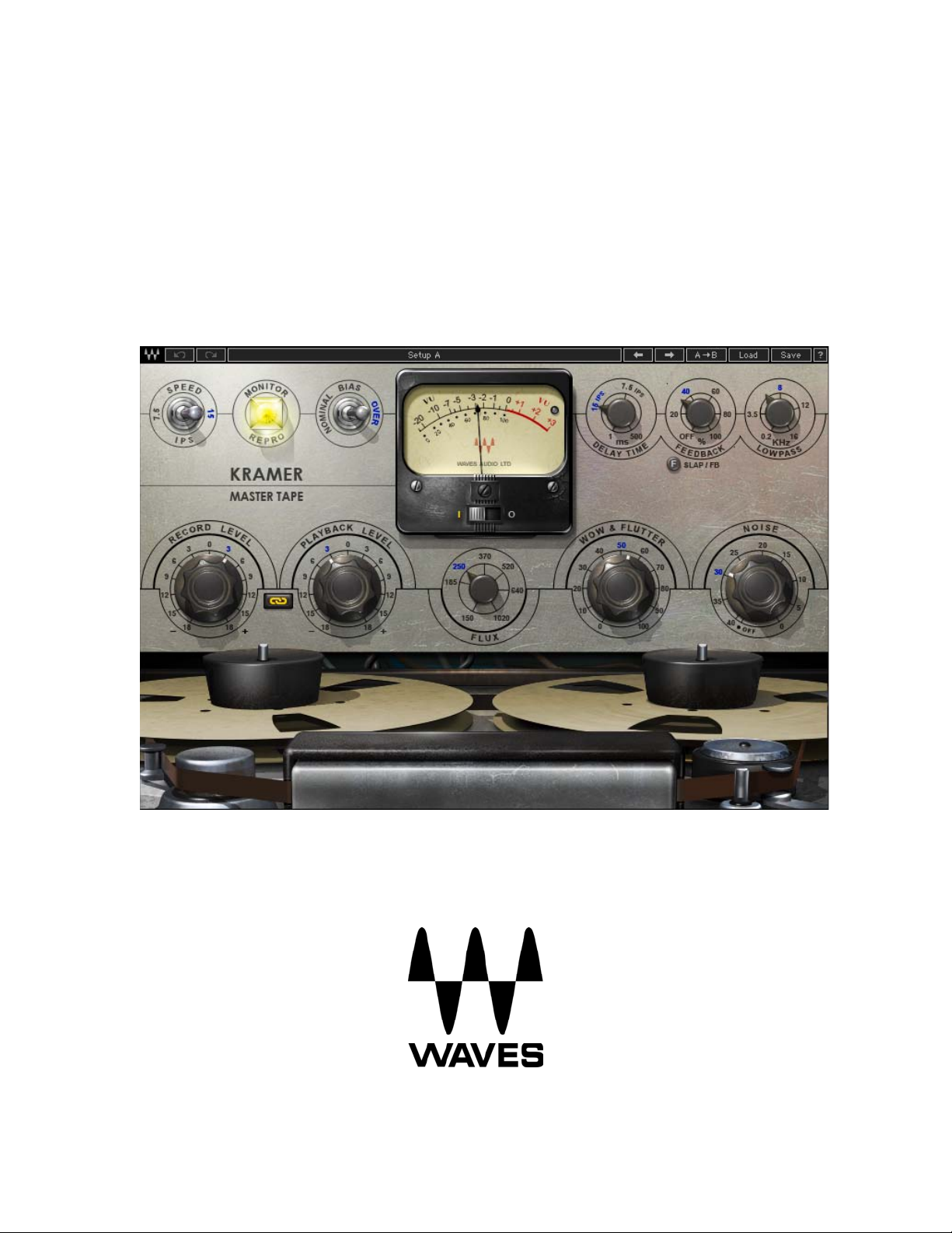
1.2 Product Overview
Developed in association with producer/engineer Eddie Kramer (Jimi Hendrix, Led
Zeppelin), the Kramer Master Tape plugin is modeled on a rare vintage ¼” tube-powered
reel-to-reel machine. A similar machine was used by Eddie Kramer during the late ’60s
at London’s Olympic Studios to record some of rock’s most classic tracks, by artists
including Jimi Hendrix, Rolling Stones, Led Zeppelin, and Traffic. Typically, it was the
final link in his recording chain, used to record the output of the Helios console (modeled
in the Kramer HLS Channel plugin), with dynamics processing by the PYE compressor
(modeled in the Kramer PIE Compressor plugin.)
With adjustable tape speed, bias, flux, wow & flutter, and modeled noise, the Kramer
Master Tape provides comprehensive control over the contours of your sound. To top it
off, we’ve added a flexible slap & fe
edback delay section.
Accurately modeling the character and sound of the machine proved quite challenging,
from the acquisition of well-maintain
ed components, generously provided by Eric
Schilling (Shakira, Gloria Estefan, Natalie Cole, Elton John), down to finding the correct
magnetic tape, in addition to modeling the mechanical and magnetic modulations and
Waves Kramer Master Tape
User Guide
3
Page 4

colorations that give these rare machines their own unique sound. Special thanks go out
to Bob Olhsson (Stevie Wonder, Marvin Gaye, Diana Ross) and especially John Haeny
(Bonnie Raitt, Weather Report, Jackson Browne, Linda Ronstadt, Jim Morrison, Tom
Jones) who provided invaluable assistance in the development of the Kramer Master
Tape plugin. You can read in greater detail about the modeling process in the White
Paper which is included as an appendix to this manual.
1.3 Concepts and Terminology
The following are a few of the terms and concepts that you will encounter while using the
Kramer
Master Tape plu
gin. You can read more about them in the White Paper
at the
end of this manual.
Tape Speed
The Kramer Master Tape offers two tape speeds: Low (7.5 inches per second or “ips”)
and High (15 ips). Low speed offers better low frequency response with some high
frequency loss, while high speed offers a more full range signal with slightly less low
end.
Input and Reproduce
When recording to tape, two monitoring modes are available. Input monitoring lets you
hear the signal as it reaches the recording head, including tube and mic-pre saturation.
Repro monitoring lets you hear the output of the repro head just like normal tape
playback, meaning that tape speed, bias, flux, wow & flutter, and noise, in addition to
tube and mic-pre saturation, all affect the monitored output.
Bias
Bias is an ultrasonic signal which is added to the recording in order to reduce limitations
of the magnetic medium. Bias calibration was a regular part of the tape machine
calibration routine and, while the manufacturers had their declared recommendations for
specific machines, many engineers felt that adding more gain to the bias signal gave
them better sound. For this reason, the Kramer Master Tape plugin offers both nominal
bias as well as overbias, which represents 3dB over the recommendation, a setting
Waves Kramer Master Tape
User Guide
4
Page 5

which became popular with many users.
Flux
Flux is the term used for the level of magnetic radiation emitted from the record head on
to the tape,
commonly referred to as operating level. Measured in nano Webers per
Meter – nWb/m, flux is essentially a gain factor reflecting a higher level passed onto the
record head. While older tapes were designed to handle lower flux levels, modern tapes
could withstand much higher flux before distorting, resulting in relatively lower noise.
Noise
The Kramer Master Tape plugin features modeled noise which is a combination of the
tape hiss ge
nerated by analog tape r
ecording, overlaid by the thermal valve noise of the
reference machine’s input and output electronics.
Wow & Flutter
The term wo
w & flutter refers to modulations and
fluctuations in speed and gain caused
by physical friction of the mechanical parts of the tape machine and the tape itself. While
the original machines were designed to minimize wow and flutter, they nonetheless have
become part of the sound we associate with analog tape. Increasing the Wow & Flutter
control makes for a rougher, more “worn” sound.
VU Meter
The Kramer Master Tape features a modeled analog VU meter, where 0 dBVU =
1.23Volts RMS = +4 dBu at 1 kHz. Using a 700
Hz tone at -18 dBFS, input and output
levels are equal. The default VU meter calibration is -18 dBFS = 0 dBVU, which we
found to be optimal for achieving the desired sound when the meter action hovers
around 0 dBVU. For hot digital signals peaking close to 0 dBFS, this will require lowering
your Record Level proportionately to achieve “proper” tape sound. When running hot
signals, the needle may stick to the right side (≥ +3 dBVU). If you are achieving the
desired sound, but would like to see some meter action, you can calibrate the meter to
Waves Kramer Master Tape
User Guide
5
Page 6

your desired headroom, and the VU meter will offset its metering so that 0 VU will
correspond to the selected headroom value.
Delay
While the original tape machine didn’t feature dedicated delay functions, many engineers
he
utilized t
machines for slap/feedback echo effects. The Kramer Master Tape plugin
offers delay times from 1ms to 500 ms, with settings for 7.5 ips (266 ms) and 15 ips (133
ms), emulating the natural slap heard when monitoring the incoming and reproduced
signals at the indicated speeds.
Waves Kramer Master Tape
User Guide
6
Page 7
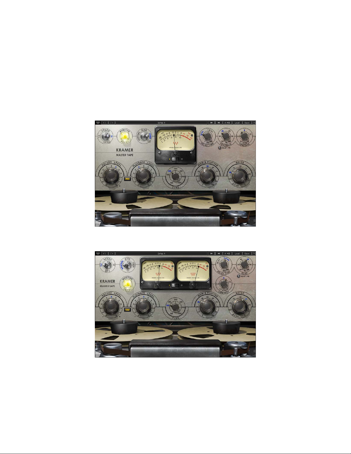
1.4 Components
The Kramer Master Tape consists of two components:
Kramer Master Tape Mono
Kramer Master Tape Stereo
Kramer
Master Tape Mono
Kramer Master Tape Stereo
Waves Kramer Master Tape
User Guide
7
Page 8

Chapter 2 – Quick Start Guide
o Insert the Kramer Master Tape on a track, group, or master.
o Go to the loudest passage in your song and, using the Record Level control,
adjust the in
put until the meter displays -5 dBVU to 0 dBVU.
o If the track has important high frequency content (e.g., acoustic guitars, vocals,
hi-hats, str
ings), use the 15 ips to better preserve high frequencies.
o If the track has a lot of low frequency information (e.g., bass, kick drum, tuba),
use the 7.5 ips to better
preserve low frequencies.
o Adjust the Flux control to increase or decrease amount of distortion.
o If needed, unlink the Record Level and Playback level and adjust levels
individually.
Please note:
recommend experim
Since input levels have a significant impact on the sound of the plugin, we
enting in order to find your optimal settings.
Waves Kramer Master Tape
User Guide
8
Page 9
Chapter 3 – Interface and Controls
3.1 Interface
Waves Kramer Master Tape
User Guide
9
Page 10

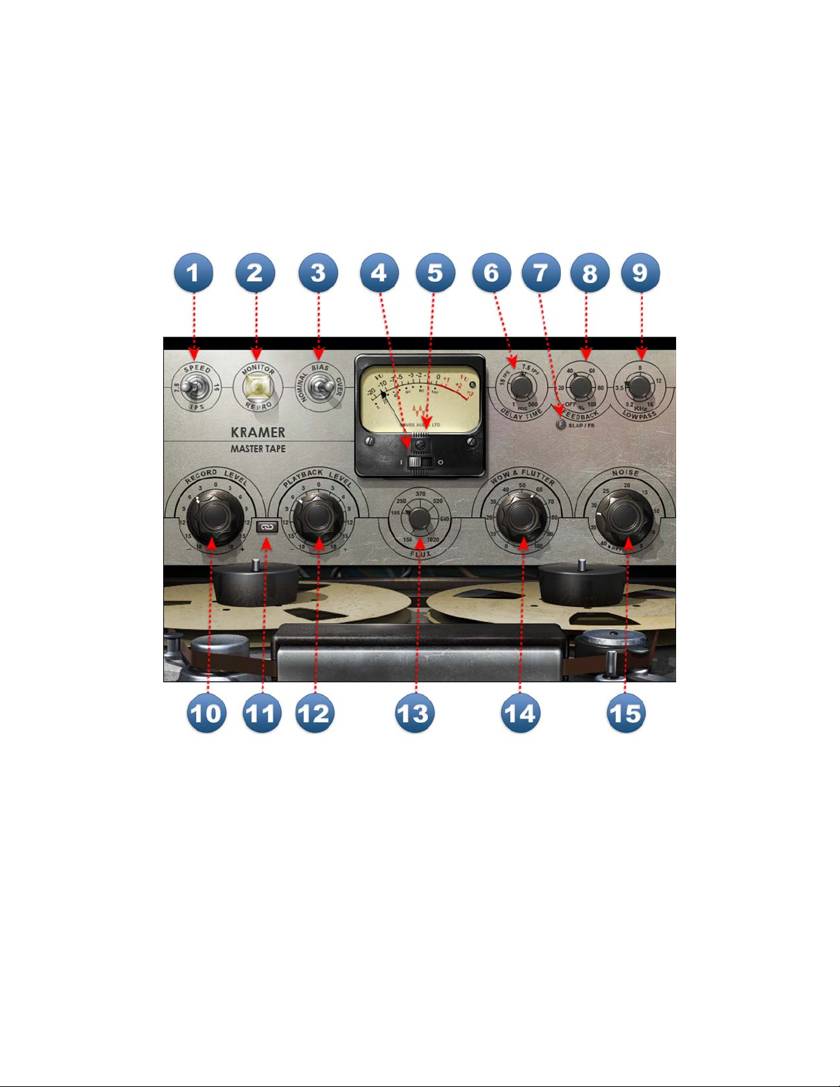
3.2 Controls
SPEED selects the simulated tape speed.
Range: 7.5 ips, 15 ips
Default: 15 ips
When switching between the two speeds, the noise and frequency response will change
accordingly; at 15 ips, high frequency response is increase
higher than at 7.5 ips.
MONITOR selects the monitoring mode.
Range: Repro, Input
Default: Repro
Repro mode monitors input stage, tape stage and output stage; Input mode monitors only
the input tub
e stage of th
e reference machine, before it goes to tape, prior to the pre-
emphasis and de-emphasis filters.
d and noise is one octave
BIAS controls the level of the ultrasonic bias signal.
Range: Nominal, Over
Default: Over
VU METER displays input or output level, depending on your selection.
Range: -20 dBVU – +3 dBVU
Waves Kramer Master Tape
User Guide
10
Page 11

VU CALIBRATION controls the VU meter headroom calibration. It is
represented by the small screw-head below the VU meter display and does not have a
visible label. For most users, the default headroom setting of 18 dB should be the best
choice. (On the Stereo component, use the screw located on the left to calibrate both
meters.)
Range: -24 dBFS – -8 dBFS
Default: -18 dBFS
DELAY TIME controls the time of the tape delay effect, with settings for 7.5
ips (266 milliseconds) and 15 ips (133 ms).
Range: 1 ms – 500 ms (continuous)
Default: 133 ms (15 ips)
DELAY TYPE toggles between delay modes.
Range: Slap, Feedback
Default: Feedback
DELAY LEVEL controls the amount of the delayed output signal.
Range: Off – 100
Default: Off
Waves Kramer Master Tape
User Guide
11
Page 12

LOWPASS controls the LP cutoff frequency on the delay path.
Range: 200 Hz – 16 kHz
Default: 3.5 kHz
RECORD LEVEL controls the input level.
Range: +/- 18 dB
Default: 0 dB
LINK I/O links Record and Playback Levels controls. The link relationship is
inversely proportional, i.e., an increase in Record Level results in a decrease in Playback
level, and vice versa.
Range: Linked/Unlinked
Default: Linked
PLAYBACK LEVEL controls the total signal output level.
Range: +/- 18 dB
Default: 0 dB
FLUX controls the level of simulated magnetic radiation emitted from the
record head.
Range: 150 nWb/m – 1020 nWb/m
Default: 185 nWb/m (Reference machine 0 dB)
Waves Kramer Master Tape
User Guide
12
Page 13

WOW & FLUTTER controls the modulations and fluctuations of speed and
gain.
Range: 0 – 100
Default: 50 (as modeled from the original)
NOISE controls the level of added modeled noise including noise
modulations and signal additive noise.
Range: Off / -40 dB to 0 (0 as modeled from the original)
Default: Off
Waves Kramer Master Tape
User Guide
13
Page 14

Chapter 4 – The WaveSystem
4.1 The WaveSystem Toolbar
All Waves plugins feature the WaveSystem toolbar which takes care of most
administrativ
features of the WaveSystem toolbar are the same on practically all Waves plugins, so
familiarity with its features will be helpful whichever plugin you are using.
Toolbar Functions
Opens the plugin About box
Undo Undoes the last 32 actions
Redo Redoes the last 32 undone actions
e functions you will encounter while working with your Waves software. The
Setup A/B
Toggles bet
ween two presets, useful for comparison of parameter
settings
L/R Arrows Move to the previous or next preset
Cop
y A→B
Copies the current settings to the second preset register
Load Recalls presets from file
Save Saves presets in the Wa
? Opens the PDF manual for the plugin you are using
ves file formats
4.2 Preset Handling Preset Types
Factory Presets are permanent presets in the Load menu. Factory presets cannot be
overwritten
or deleted.
When applicable, different component plugins may have different
factory presets.
User Presets are your favorite settings of the plugin saved as a preset in the Load
menu, under ‘User Presets’. User Presets can b
e overwritten and deleted.
Setup Files may contain more than one preset. For example
, a single file can contain all
the presets for a session. When you open a Setup File, all its setups become part of
your Load pop-up menu for fast access. This can be particularly useful with multiple
instances of a plugin in a single session. By saving all the settings you create into a
single Setup File, they can all be quickly available for every instance of that plugin.
Waves Kramer Master Tape
User Guide
14
Page 15

Loading Presets and Setups
Click on the Load button to see the Load pop-up menu. The menu is divided into four
sections. If a section is not currently available it will not appear in the Load pop-up menu.
Open Preset File… Select to op
en any setup or preset file, whether from the Library or
your own creations.
‘Filename.xps’: Displays any currently loaded Setup File and it
Factory
Presets: Displays the default Factory Presets.
s presets.
User Presets: Displays any loaded User Presets.
Saving Presets and Setups
Click on the Save button to see the Save pop-up menu. Four options are available. If an
option is not
currently available it will be grayed out and inaccessible.
Save to New
File… Select this to start a ne
w Setup file. There are two
prompts - first for the setup filename, then for the
preset name. You must provide a name for both the
setup file and the preset. Click OK (ENTER) to
complete the save. It is a good idea to create a
folder in which to save several setup files for a
project.
Save ‘File Name’ – “Preset Name” Overwrites the settings of the loaded preset
(whether a User Preset or a preset from a Setup
File) with the current settings. If a Setup File is
currently loaded, the name of the Setup File is
displayed followed by the name of the preset itself.
If a User Preset is loaded, its name is displayed.
Save to ‘File Name’ As…
Saves the current settin
gs as a new preset into the
Setup file that is open (if one is not open, the option
is grayed out). You will be prompted to give the
preset a name.
Put into Preset Menu As… Save the current setting
s into a User Preset that
will always be in your Load menu (until deleted).
You will be prompted to give this preset a name.
User Presets are stored in the plugin’s preference
file.
Please note: Special characters (such as: !, @, #, %, ^, etc.) are not supported in preset
es.
nam
Waves Kramer Master Tape
User Guide
15
Page 16

Deleting Presets
You may delete User Presets and presets within a Setup File. Factory Presets and
Setup Library files cannot be deleted
or overwritten.
1. Hold the Command (Mac)/Control (PC) key down.
2. Click-and-hold the Load button to see the pop-up menu.
3. While still holding the Command/Control key, select the preset or setup to delete.
4. A confirmation box will appear, allowing you to cancel or ‘OK’ the deletion.
A/B Comparison and Copying
The Setup A/Setup B button may be clicked to compare two settings. If you load a preset
in the Setup B position, t
his will not affect the preset loaded into the Setup A position,
and vice-versa.
If you want to slightly modify the settings in Setup A, you can copy them t
o Setup B by
clicking on the Copy to B button, then alter Setup A and compare with the original Setup
B.
The name of the current setup will be shown in the title bar (on platforms which support
m
it), and will switch as you change fro
Setup A to Setup B.
Note: an asterisk will be added to the preset name when a change is made to the preset.
4.3 Interface Controls
Controls can be in one of three states:
• Not Selected where the control is not the target of any user entry
• Selected where the con
• Selected and Active where the control is the tar
keyboard entry
Toggle Buttons
Toggle buttons display the state of a control, and allow switching between two or more
states.
Sing
le-click to change the control’s state. Some toggle buttons have a text
display which updates with the current setting, and others (bypass, solo, or monitoring
toggles) illuminate when the control is active.
Some plugins have link buttons between a pair of toggle but
drag adjustment while retaining the offset between the controls.
trol is the target of mouse control entry only
get for both mouse and
tons, allowin
Waves Kramer Master Tape
User Guide
16
g click-and-
Page 17

Value Window Buttons
Value windows display the value of a control and allow click-and-drag
adjustment, or
direct control via the keyboard.
• Using the mouse, click-and-drag
windows support left/rig
ht, some up/down (as you hover over a button, arrows
on the value window to adjust. Some value
will appear to let you know which direction of movement that button supports).
You may also use your mouse-wheel to adjust parameter values.
• Using the arrow
s, click once with mouse to select the button, and then use
key
up/down – left/right (depending on the direction supported by that button) to
move in the smallest incremental steps across the button’s range (holding down
the arrow keys will move faster through the range).
• Using key
entry, double click on the button to open the value window, and
directly enter the value from your keyboard. If you enter an out of range number,
the button stays selected but remains at the current setting. (System beeps if
system sounds are on.)
Some plugins have link buttons between a pair of value windows, allowing click-and
drag adjust
ment while retaining the offset between the controls.
-
Sliders
Click or scroll the mouse-wheel on the slider itself or anywhere within the sliders track.
The numerical value of the slider set
tings is
displayed in a hover window above the
slider path.
Hover Box
Hovering boxes will appear and display the control value when hovering with the mouse
over the control.
Multiple Control Selection
One of the most powerful features of the WaveSystem is the ability to select and adjust
multiple con
trols simulta
neously. Using the mouse, drag-select the desired group of
buttons or graphic controls by clicking and holding at a point outside the controls, and
forming a rectangle that includes the controls you wish to adjust. Alternatively, press and
hold Shift while clicking the mouse on any control you wish to link. This method is useful
when you want to select two or more controls that are not adjacent to one another.
TAB Functions
TAB moves the ‘selected’ status to the next control, with shift-TAB moving in the reverse
direction.
Waves Kramer Master Tape
User Guide
17
Page 18

Additionally, the Mac has an option-TAB function for ‘down’ movement and shift-optionTAB for ‘up’ movement
If you have several Value Window Buttons selected, TAB functions will take you through
the selected
Hitting Esc or Return will return the 'focus' to the DAW application.
controls on
where applicable.
ly.
4.4 Waves Preferences (Pro Tools only)
When launching Pro Tools, hold Shift to view the Waves plugin Preferences window.
The followin
g options ar
• Don't use AudioSuite plugins
• Don’t use RTAS plugins
• Rescan all plugins
• HUI control surface support (low resolution)
• Enable single-click text entry
e available:
Waves Kramer Master Tape
User Guide
18
Page 19

Chapter 5 – Appendix
KRAMER M ASTER TAPE WHITE P APER
Written by John Haeny
Based on an original outline by
Mike Fradis, Waves Product Manger
Edited by Michael Costa
Bias Definition by Michael White
Introduction
When Waves started a hardware modeling project with Eddie Kramer, it was always
their intention to create a
London that Eddie used on his great recordings of Led Zeppelin, The Rolling Stones and
Jimi Hendrix. The model of the Helios Console Channel was challenging, resulting in the
Waves Kramer HLS Channel. Next was the modeling of the famous PYE compressor
which was released as Waves Kramer PIE Compressor.
Missing from this ‘golden’ chain was the classic American tube analogue tape machine
used for these recordings. Waves acquired what they believed was the right machine
and set about modeling, knowing it would be difficult based on what was already on the
market. As it turned out, the task was much more daunting than anticipated and Waves’
first attempt, the initial Kramer Master Tape, was withdrawn shortly after being
introduced into testing. It turned out that this third piece of the Kramer Olympic chain
was going to be the hardest.
Waves discovered (along with the guidance of so
missing a number of things, each one extremely complicated by itself, and in total
representing a huge challenge. Thanks to the guidance of Bob Olhsson and John
Haeny, Waves were ultimately directed to the correct transport and tube electronics.
With Bob’s help, one of these rare beasts was found in Florida owned by Eric Shilling.
Eric kindly agreed to let Waves do some preliminary testing to ensure that this machine
was producing the sound that both Bob and John had missed in Waves’ first effort.
To clarify what appears to be a contradiction regarding the Olympic tape machine being
an American product in a British stu
Kramer was working at Olympic Studios in London, it was these American tape
machines that Olympic and their clients were using as master recorders.
This world famous tube tape machine was the mainstay of the recording industry
(particularly in
erica) and was used for literally thousands of hit albums and singles
Am
over more than two decades of recording. For example in 1954, an early tube analogue
reel-to-reel tape machine recorded the historic first single of an unknown truck driver
named Elvis Presley, "That's All Right" at Sun Studios in Memphis. This same reel-toreel tape machine was also the backbone of the earliest days of multi-track recording.
The first of the 8-track versions of this recorder was custom built for and sold to Les Paul
model of the original recording chain from Olympic Studios in
e of their Beta team) that they were
m
dio, it should be made clear that at the time Eddie
Waves Kramer Master Tape
User Guide
19
Page 20

for $10,000 in 1957, and was installed in his home recording studio. It became known as
the "Octopus”. 8-track serial number #3 of the same machine was sold to Atlantic
Records at Tom Dowd’s insistence in early 1958. Atlantic Records was the first record
company to use a multi-track recorder in their studio on a regular basis. Just pause for a
moment and contemplate all the great recordings that came out of that Atlantic Records
recording studio. If they ever were to induct a tape recorder into the Rock and Roll Hall
of Fame, this would be the machine!
With the modeling project still appearing workable, it turned out that the recording curve,
tape speed,
tape emulsion, tape thickness, f
lux or level recorded on the tape (more
later), and the bias settings all greatly impacted the final result. So again, with Bob and
John’s help, endless discussions and tests were made regarding tape types and
alignment techniques until what Waves were going to model was finally settled. Over
time and with much experimentation, they made sample recordings that both Bob and
John agreed had established a solid baseline from which to proceed. It would be these
initial samples of the test recordings that would be used for detailed comparison to
ensure that each model was performing accurately.
Once again, Eric Shilling came to the rescue and agreed to do the massive testing and
modeling runs required to model the two primary
tape speeds, a number of tape
emulsions plus variations in flux and bias settings as well as approaches to alignment
techniques.
With the modeling files in hand, Waves began the excessively complex task of creating
models, not only of the variety of analogue tape r
ecordings, b
ut the variety of bias, flux
levels (tape saturation) and speed settings. When Waves began evolving early stage
Alpha plugs, they required painstaking subjective analysis by comparison to the original
samples recorded on the original tape machine and then through feedback to the
development and engineering team, the models were honed. Because Waves felt they
could best do their development using only one platform at a time, they chose to do their
final development on the Macintosh, at which time Bob, who primarily uses a PC, offered
to take a back seat. John volunteered to take up the slack and became a more or less
full-time co-developer of the Kramer Master Tape plugin.
WHAT WAS MODELED AND HOW DOES THAT AFFECT THE GUI
AND THE OPERATION OF THE K RAMER MASTER TAPE?
Tape Type
Waves modeled 3M Scotch 207 tape as it was considered an excellent match for this
machine. Originally 3M Scotch 111 t
ape would have been the tape of ch
during the early days of analogue tape recording. There were other earlier tape types
that were exceedingly popular as well - for example, 3M Scotch 201/202/203 was used
extensively by Motown, but sadly it was no longer available in a sufficient and durable
enough quantity for this project. Waves was also able to source an amount of an earlier
tape stock, 3M Scotch 131, but sadly the quality was poor and it did not hold up during
oice for many
Waves Kramer Master Tape
User Guide
20
Page 21

the modeling process. Because the members of the Waves team had extensive
experience with 3M Scotch 206 (a 1.5 millimeter base) and 3M Scotch 207 (a 1.0
millimeter base), 207 was selected because of the slightly thinner base, although
perhaps subject to greater print-through (clearly not an issue for a tape modeled plugin),
207 provided a more intimate recording and playback head contact (called ‘tape wrap’)
and thus produced a more extended high frequency response. Fortunately John Haeny
had a sufficient supply of virgin 3M Scotch 207 stock for the purpose so off the shipment
flew from Australia to Florida.
Tape Speed
The original machine’s transport has 2 speeds: 15 ips (inch
e
s per second), and 7.5 ips.
15 ips was the default professional standard providing the best high frequency response
and the lowest noise. 15 ips has a gentle roll off at around 16 kHz. 7.5 ips was the
minimum reasonable professional quality speed for studios and there was also a fair
amount of equipment for the home that operated at 7.5 ips. 7.5 ips has quite a high
frequency loss with a roll-off starting at around 8 kHz, but 7.5 ips managed to preserve
low frequencies better than 15 ips with a slightly more ‘solid’ bottom end and therefore
was widely used in rock recordings in the 60’s and 70’s.
When switching between the 2 speeds you should expect to get a very much improve
d
high frequency response with 15 ips when compared to 7.5 ips but perhaps a somewhat
less tight low end. Note that 15 ips will also provide less THD (Total Harmonic Distortion)
than 7.5 ips. There is also a shift in the frequency of the noise by an octave between 7.5
ips and 15 ips, with the noise at 15 ips sounding an octave higher than 7.5 ips. The
significance of this difference has always been argued, with some preferring the noise
signature of 7.5 ips and others preferring the noise signature of 15 ips. As time
progressed and 30 ips became popular, many used 30 ips because as the noise shifted
upwards yet another octave from 15 ips, it moved further away from the fundamental
musical frequencies and thus became less obtrusive. Experiment and form your own
opinions on the issue of speed vs. noise vs. frequency response.
Pre-Emphasis Curves
At the time of the modeled tape machine’s popularity, there were a number of magnetic
s
tape recording standard
in use worldwide. Because of the inherent limitations in
analogue tape recording, these curves generally applied high frequency pre-emphasis
equalization during recording and then applied a high frequency post-emphasis during
playback. The net result of this was to maintain high frequency response according to
the standard being used with the added benefit of also reducing tape noise.
The most popular standard in Europe at this time was CCIR; in America, the standard
was NAB (National Asso
ciation of Broadcasters). The machine at Olympic, as best we
can determine, was a NAB machine although the manufacturer would provide CCIR
machines on special order. Additionally, NAB was the standard used for the vast
majority of the American pop recordings done on this machine. Because the NAB
standard provides the most accurate sonic signature of this legendary American tape
machine, the NAB standard was chosen by Waves for the Kramer Master Tape model.
Waves Kramer Master Tape
User Guide
21
Page 22

Bias
Defined: Bias is a high frequency signal, typically between 40 kHz and 150 kHz,
applied to the record he
ad along with the audio signal when an audio track is
placed into record. The bias current solves a critical problem when recording to
analog tape. When the amplitude of an audio signal passes through the zero
voltage crossing, the magnetic field created by the record head is not strong
enough to polarize the magnetic oxide particles on the tape. Thus, a distortion of
the original audio signal is introduced. To minimize this distortion, the bias
current is applied to break down this resistance to polarization. The audio signal
can then be recorded more accurately without the effects of low level distortion.
The amount of bias current applied is critical to the frequency response and
distortion characteristics of an analog recording.
Waves modeled and have provided you with two bias settings. “Nominal Bias,” the
manufacturer’s recommendation for bi
as adjustment (directly from the original operator’s
manual for the modeled machine) was recommended in the early years to try and reach
the best recording levels with the minimum amount of distortion and the maximum
frequency response. This setting produced a fairly low noise level (around 60 dB lower
than the peak signal), and around 2 to 3 dB of high frequency loss with a moderate
amount of high frequency distortion.
During the ’60s, after a number of years of working with these tapes, many professio
studio engin
eers and technicians discovered that by over biasing (increasing the
nal
amplitude of bias signal) by only a small amount, they could improve the high frequency
response and at the same time lower the noise level. This was called “Over Bias” and
each tape type, studio, recording engineer and technician had their own way of
calibrating the bias to achieve their preferred sonic qualities.
For the Kramer Master Tape, we modeled the -3 dB over bias, which was agreed b
y
most engineers to be the point where you got the best high frequency response, least
amount of distortion and best signal to noise ratio on 3M Scotch 207 tape. (Actually -.7
dB at 700 Hz for 15 ips, but set at -3 dB at 15 kHz for accuracy. You adjusted nominal
bias to accomplish the peak level of the signal and then continued beyond the peak until
the level began dropping by the desired amount, therefore the term ‘over bias’. The bias
adjustment for 7.5 was done one octave lower at 350 Hz or 7,500 Hz and at -20 dB to
avoid excessive high frequency saturation.) When you switch from “Nominal Bias” to
“Over Bias” mode, you should expect to hear a bit less noise, clearer high frequencies
(reduced distortion), and a bit more overall dynamic range (and clarity, once again the
result of less overall THD).
Flux
Defined: The magnetic flux density recorded on a tape (level). The standard unit
in measurin
g the amount of magnetic energy recorded to tape is expressed in
NanoWebers per meter (commonly abbreviated as nWb/m). When picking an
operating level for tape (flux/level), the general rule is that the higher the
operating level, the further away you are from the noise floor but the closer you
are to the point of distortion. This dynamic is highly dependant on the tape stock
being used. For a detailed dissertation on magnetic recording flux and fluxfrequency measurements please use this URL
Waves Kramer Master Tape
User Guide
22
Page 23

http://home.comcast.net/~mrltapes/mcknight_flux-and-flux-frequency-responsemeasurements.pdf
Flux is the magnetic density recorded on the tape per meter (nWb/m
), the higher the flux
level - the higher the recording level on the tape. In order to reach higher recording
levels you need to have tapes that can manage a higher flux level (many modern tapes
can reach very high recording levels with minimum distortion with the added benefit of
reduced noise or ‘tape hiss’).
The manufacturer initially established a recording level for recordings made on their
machines d
uring the 19
50s. This was called Standard Operating Level. This recording
level was at a flux level of 185 nWb/m. All early alignment tapes were Standard
Operating Level or 185 nWb/m signals and eventually became the standard for all
magnetic tape recording. As tapes were developed to handle greater and greater flux (or
higher recording) levels, the industry continued to rate tape flux levels based on the
original Standard Operating Level. For example, a tape that was designed to record
signals at 250 nWb/m was said to be recording at +3 dB (over the Standard Operating
Level of 185 nWb/m). As a point of reference, since the Flux Control on Kramer Master
Tape is calibrated in nWb/m, here is a quick reference guide for comparison (Source
Quantegy):
-2 dB = 150 nWb/m
0 dB = 185 nWb/m (Standard Operating Level)
+3 dB = 250 nWb/m
+5 dB = 320 nWb/m
+6 dB = 370 nWb/m
+9 dB = 520 nWb/m
Science aside, early on many engineers discovered that by pushing or abusing the
recording le
vels on tapes, it created
some very musical and frequently desirable sideeffects, especially in Rock and Roll recording. Tape has a very unique way of going into
saturation or overload, whereas digital is basically ‘go or no-go’ with over-modulation
producing clipping. As the levels are raised on analogue tape, a number of things
increase simultaneously and fairly gradually: Total Harmonic Distortion (THD), Intermodulation Distortion (IM), Modulation Noise and a mix of other aberrations and for ms
of distortion, many of which are still not fully understood. Also, when tape is pushed hard
enough, it has a tendency to ‘saturate’ which is a form of compression, unique to
analogue tape. Many engineers, even when digital was available, still preferred to record
certain instruments on analogue tape (especially Rock and Roll drums) pushing the
levels on the tape well beyond their ideal operating conditions to gain this saturation or
compression.
Modeling this behavior of changing sonic behavior across a wide range of flux levels was
perhaps one
of Waves’ biggest cha
llenges. Ultimately they were able to create a
continuous flux control that ranges from -2 dB below the Standard Operating Level well
into unknown territories, invaluable for a wide variety of special effects.
Since 3M Scotch 207 was rated at between 185 nWb/m or 250 nWb/m
(while opinio
ns
vary about the ‘ideal’ level for Scotch 207, Waves chose the more conservative level of
185 nWb/m for the Kramer Master Tape default, although they modeled a wide range of
flux levels to be able to accurately create the variable flux control), you will find that the
Waves Kramer Master Tape
User Guide
23
Page 24

plugin will be especially sensitive to settings above the recommended level of the tape
sampled. When reaching higher flux levels you will notice that the low frequencies and
very high frequencies become more and more distorted as the noise level goes down.
Additionally there is another layer of distortion since these increased operating levels
also stress the tube input and output stages, giving you the bonus of an additional level
of overall “tube distortion.”
Kramer Master Tape is the first tape modeling plugin that has actually managed to
create a con
tinuously variable flux control, lettin
g the user sonically understand the
changes between different recording levels. Add to this that this is also being done on a
fully tube electronics tape machine and you truly have a one of a kind plugin - unique in
the industry.
As an added feature, using Kramer Master Tape in the input only mode allows you to
add the sou
nd of the inp
ut and output tube electronics, minus the sound of analogue
tape recording. Increasing the record level as you reduce the playback level (to maintain
unity gain) increases the tube saturation of the input and output amplifiers, independent
of the flux control (which only affects tape saturation). These controls can be used either
in conjunction with the sound of the tape saturation, or without the tape saturation to
create just the sound of these unique tube amplifiers operating across their entire range
of saturation.
Because of the independence of the flux control and the record level and playback level
controls, you have full control over both the tape
saturation and the tube saturation while
maintaining the level of the Kramer Master Tape track in your mix (using the ‘Link’
function for the record and playback controls).
To simplify the Kramer Master Tape Flux control, just think of it as a ‘tape drive’ or
‘saturation control’. As you increase the flux level on the tape the output of the
Kramer Master Tape plugin stays constant at unity gain unless you choose to
adjust the output gain control.
Noise
Although the Noise control on the Kramer Master Tape is defaulted to off, it is strongly
suggested that you take a listen to it. If this can be said, you may find it to be some of
the sweetest noise you will ever hear since it is a combination of the tape hiss generated
by analogue tape recording, overlaid by the thermal tube noise of this historic machine’s
input and output electronics.
Wow
Defined: Wow and flutter in analogue tape recordings results from the turning
speed inaccuracies (FM), and flutter effect (AM) caused from changes in
the
physical alignment of the tape on the actual recording head, coupled with the ‘slip
and slide’ of the tape going through the transport mechanism and a variety of
mechanical ‘frictions.’
In a perfect world, there would not have been wow and flutter. Many ‘in the day’
considered wow and flutter the same as surface
noise on a vinyl disc - just something
negative one had to live with since that was the ‘state of the art.’ But like noise, there are
Waves Kramer Master Tape
User Guide
24
Page 25

many that will feel that any model is not complete without all the flaws as well. For that
reason, Waves has provided you a manual wow control on the plugin’s graphic interface.
It is defaulted to the wow and flutter modeled on the sample machine. You can increase
it for a somewhat more enhanced effect (although it would have never been too obvious
[unless your machine was broken] as it was always a subtlety of the analogue tape
process), or if you choose, you can move to a more idealized world and turn the wow off.
Having or not having wow and flutter and/or noise has nothing to do with the primary
advantages of the analogue tape recording sonics, so use them or not at your own
discretion. You will always have the advantages of the Kramer Master Tape sound with
or without them.
Something Extra
To sweeten the Kramer Master Tape package, Waves also added a variable delay
control (0 ms-500 ms
) that routes the tape playback of the plugin back to the input of the
Kramer Master Tape. This creates a very basic feedback tape delay effect across the
entire signal (the direct signal is always included in the mix). A low pass (LP) filter was
added to the delayed feedback path to allow you to filter out any unwanted high
frequencies. This delay/feedback feature is intended to be very basic. It does not offer a
wide control section, but is believed to contribute additional value to the Kramer Master
Tape plugin. Used carefully, this function has the capacity to create some very lovely
tape delay sounds. It also needs to be pointed out that the delay is only affected by the
Delay Time control in the delay section. It is NOT affected by the running speed of the
transport. If you need to ask why Waves included this bonus function, the answer is
quite simple...because they could, and they were confident that you would enjoy it!
WHAT TO EXPECT FROM THE KRAMER MASTER TAPE
Default Set-Up
The default set-up of the Kramer Master Tape, without any adjustments, will provide
identical re
sults to havin
standard curve with an over-bias of -3 dB at 15 kHz and at a recording flux level of 185
nWb/m. This will yield the sound of the basic industry set-up for this machine at the
height of its era. The only item remaining for you to decide will be whether or not to have
tape and tube amplifier noise, and if so, exactly to what degree.
Of course you also have other options with regard to bias, wow, speed and most
dramatically, a continuo
of -2 dB below the classic Standard Operating Level all the way to some rather massive,
heretofore unattainable in a plugin, extreme analogue tape saturation effects.
Meter Transfer Switch
On the face of the meter, you will find a switch that lets you choose whether the meter
displays the
plugin’s
effect on the monitored sound.
g made your recording on 3M Scotch 207 at 15 ips using a NAB
usly variable flux cont
rol starting at the ultra conservative setting
input or its output. This is purely a meter transfer switch and has no
Waves Kramer Master Tape
User Guide
25
Page 26

Mode Switch or Input/Reproduce
In place of the classic record light you will find an illuminated yellow or amber lamp. The
label above it will be in t
he default mode of Repro, which means the outp
ut of the
Kramer Master Tape is after the model of recording on tape. (i.e., in Repro mode, you
are hearing the sound of the playback head reproducing the signal previously recorded
by the record head.) In the Input mode, you will only be hearing the sound of the tube
input and output electronic stages (or directly through the machine without any tape
running). This is not a pure bypass and this sound is, in and of itself, valuable for many
applications. Other than the audio monitor transfer and the light being on for Reproduce
and off for Input, when in Reproduce the transport reels will also be turning to insure you
that you are hearing the result of recording on analogue tape. Should you choose not to
have the reels turning, simply clicking on them will turn their motion off.
What Should You Expect to Hear
The sound of analogue magnetic tape recording may be new or un-familiar to some born
in the digital age. The g
oal of the design of all analogue tape recorders was the same to provide a transparent, colorless method of media storage. The machine we modeled
was quite successful in its day, at accomplishing this goal. But because of the state of
the art at the time of this machine’s development, it still had a wide variety of limitations:
Tape saturation, tape noise, harmonic distortion, modulation noise, phase shift and
limitations in frequency response to name but a few.
Although many think that analogue tape will improve the sonic quality of their signal, by
today’s standards and measurements it does qu
ite the opposite. Measured by modern
technology it lowers the overall resolution of a signal. In fact the signal to noise ratio of
an analogue tape recording is not good by today’s standards. It fails to accurately
reproduce both high and low frequencies. Its THD (Total Harmonic Distortion)
measurements are not good by current standards (more than 1% THD) and yet listeners
still find its sound pleasing.
So just why is this sound so desirable? Well for a number of reasons, but firstly, contrary
to measurements and the theoretical loss o
h frequency response, because of the
f hig
non-linearity of the NAB standard, coupled with the third harmonic distortion created by
the analogue recording process, the ultimate subjective result is a slight increase in the
quantity and clarity of the higher frequencies.
Even as digital recording has come of age, and with hindsight 20/20, what many
considered t
o be a limita
tion of analogue tape recording, has in fact become desirable.
Digital has been criticized by many as being clinical and cold sounding, while analogue
technology has been touted as sounding warm, clear and musical. Therein lies the big
difference in what you should hear in the plugin. Granted, if you want to play with the
settings (and please feel free to do so) you can create some very dramatic tape effects
of saturation, noise, etc. But by using the Kramer Master Tape with its default setting, it
will provide you with an extremely accurate model of, not only tube analogue tape
recording, but of analogue tape recording on what many considered to be the premier
tube analogue tape recorder of its era.
Waves Kramer Master Tape
User Guide
26
Page 27

A description of the sound of the Kramer Master Tape is that it is best ‘felt’ as a warm,
sweet and clear musical sound. Start there as your basis and then experiment with the
controls to discover all the additional sonic qualities available to you, and choose those
that best suit your tastes and your style of music.
In Practical Application
It is not possible to create a model with this level of detail and flexibility and at the same
time keep it
s resource d
emands low. Running Kramer Master Tape does require a fair
amount of system resources as you might expect. If you want to use the plugin on
individual tracks, please do so, as there are no ‘rules’ in our art form. But Kramer Master
Tape may perform best on sub-mixes of drums and percussion, strings, guitars, vocals
and anything that requires analogue ‘warmth and clarity.’ Also, don’t forget what the
plugin could contribute to digitally sampled instruments and digital synthesizers. Many
will find that across an entire mix and especially in mastering, Kramer Master Tape may
prove to be invaluable. The Kramer Master Tape plugin is the result of almost two years
of failures and triumphs, and contains the heart and soul of many contributors. Waves’
sincerest hope is that you will enjoy Kramer Master Tape, and that it will become an
invaluable component in your sonic toolkit.
Kramer Master Tape used in conjunction with the Kramer HLS and the Kramer PIE
finally completes the magic of the original
Kramer Olympic Studio recording chain.
Waves Kramer Master Tape
User Guide
27
 Loading...