

Page 1
WAVES/ABBEY ROAD
EMI TG12345
USER GUIDE
Page 2

2
TABLE OF CONTENTS
CHAPTER 1 – INTRODUCTION ......................................................................................................3
1.1 Welcome .............................................................................................................................................................................................3
1.2 The Original EMI TG12345 Console ...............................................................................................................................................3
1.3 The EMI TG12345 Plugin ..................................................................................................................................................................4
1.4 Concepts and Terminology ..............................................................................................................................................................5
1.5 Components........................................................................................................................................................................................7
CHAPTER 2 – INTERFACE AND CONTROLS .............................................................................8
2.1 Inte rface ..............................................................................................................................................................................................8
2.2 Controls ...............................................................................................................................................................................................9
CHAPTER 3 – THE W AVESYSTEM ............................................................................................ 14
3.1 The WaveSystem Toolbar ............................................................................................................................................................. 14
3.2 Preset Handling............................................................................................................................................................................... 14
3.3 Inte rface Controls........................................................................................................................................................................... 16
3.4 Waves Preferences (Pro Tools DAE only) .................................................................................................................................. 18
Abbey Road Studios and their associated logos are trademark s of EMI (IP) Limited.
Waves/Abbey Road TG12345
User Guide
Page 3

3
Chapter 1 – Introduction
1.1 W el come
Thank you for choosing Waves. In order to get the most out of your Waves processor, please take
the time to read through this manual.
In conjunction, we also suggest y ou become familiar with www.wavesupport.net
an extensive Answer B ase, the latest Tech Specs, detailed Installation guides, new Software
Updates, and current information on Authorization and Registration.
By signing up at www.wavesupport.net
products, reminders when updates are available, and information on your authorization status.
, you will receive personalized information on your registered
. T here you will find
1.2 The Original EMI TG12345 Cons ole
In 1968, the introduct ion of 8-track recording and increasing sonic experimentation by the Beatles
and other groundbreaking artists meant that the capabilities of A bbey Road Studios’ REDD .37 and
REDD .51 consoles were being stretched to the max. This called for a new desk.
The year before, EMI had already laid out ideas for a solid-state mixer to replace the valve REDD
desks . Thr oughout 1967, meetings had taken place between the Abbey Road s t aff and the
engineers at EM I Central Research Laboratories in order to design a comprehensive mixing console
that would be able to handle the needs of the lates t music recordings.
The resulting console, TG12345, was designed to meet the most demanding recording
requirements of its time. I t was substantially bigger than the old REDD desks, with 24 mic inputs
and 8 outputs, 4 echo sends, 2 CUE/foldbacks, and, for the first time ever, a compressor/limiter on
every channel, in addition to EQ. The c om pr es s or was bas ed on the valve Fair c hild and Altec
devices used at Abbey Road during the '60s, but ended up with a completely unique sound all its
own. The desk was also modular in design, with twelve microphone ‘cassettes’, or channel strips,
that could easily be replaced when faulty. Each cassette contained two input channels that could be
used either separately or as a stereo pair.
All in all, the des k had no less than 479 knobs and controls as well as 37 meters. Since it was larger
than other cons oles (a staggering 79. 5’’ in widt h), engineers sitt ing at the center of the desk were
unable to reach all the controls.
Waves / A bbey Road TG 12345
User Guide
Page 4

4
For several months in the summer and fall of 1968, the new desk was placed in the studios’
‘experiment al room ’ for testing. Abbey Road’s engineers r an ‘clone’ sessions to compare TG12345
and REDD, with two sets of mics placed in the room: one going to the REDD .51, the other to the
TG. The results were superb: TG12345 proved to have a cleaner, brighter and punchier sound than
its predecessor, with unprecedented top end sheen and sparkle.
On the weekend of November 23, 1968, TG12345 MK I was ins talled in the c ontr ol room of Abbey
Road’s Studio Two and connected to the 3M 8-track tape machine. It was first used in a recording
session with the Shadows. In mid-1969, the very last Beatles album, Abbey Road, was made on the
TG12345.
The TG12345 went through several revisions during the 1970s. TG12345 MK II replaced the treble
filter with the same presence filter that existed on the main and group cassettes of MK I. The
ergonomics of the dynamics section also underwent changes. MK II I and MK IV added new utility
options, but the sound processors (dynamics and filters) remained unchanged.
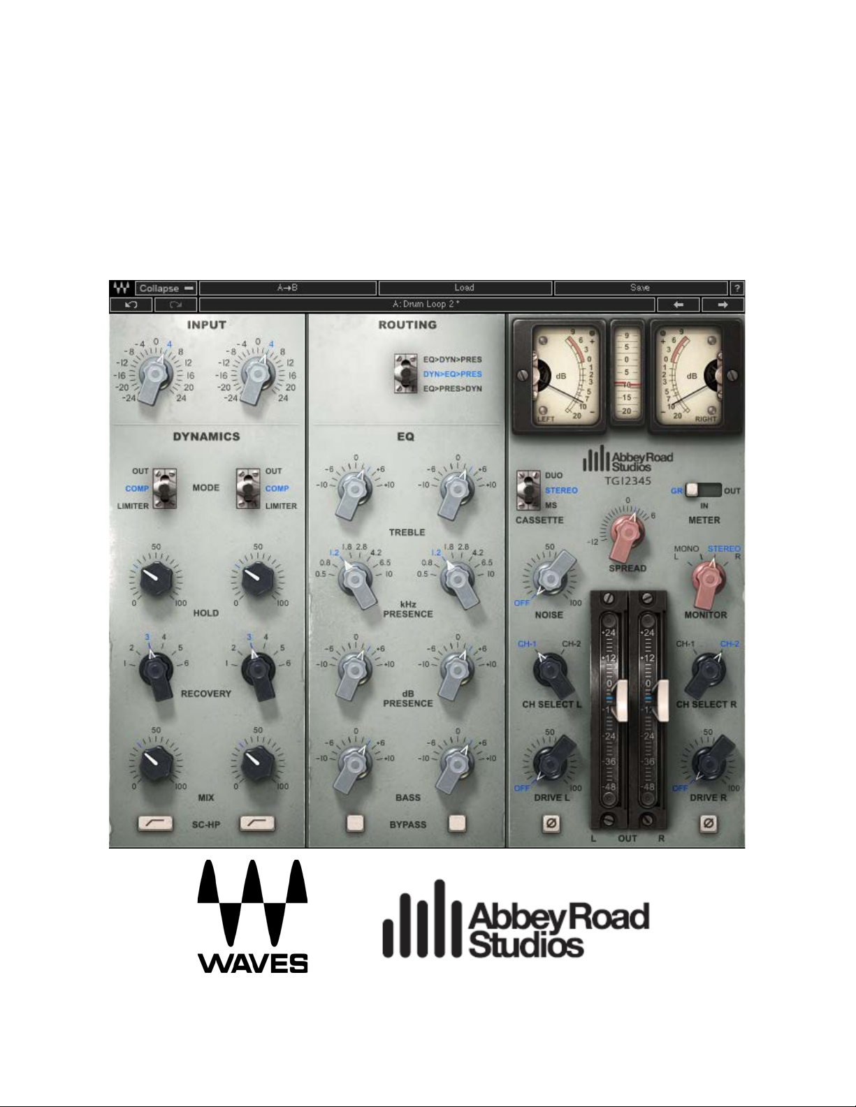
1.3 The EMI TG12345 Plugin
The TG12345 plugin is a channel strip with a three-band EQ. Its treble filters deliver a fixed bell filter
at 5K for boost, and a fixed shelf filter at 10K for cut. The bass filters are fixed shelf filters at 50 Hz.
W e have also added a bell filter for presenc e boost/cut, ranging from 500 Hz to 10 kHz. In the
original TG12345 MK I des k, the presenc e filter was part of the group cas s ette. We have added it to
the TG12345 channel strip for a better user experience.
The TG12345 has a Dynamics section with a limiter/compressor (7:1 and 2:1, respectively) that has
a fixed attack time and six options for release time.
The plugin offer s thr ee routing opt ions , allowing users to determine where to place the EQ (Bass +
Treble), Presence, and Dynamics sections within the signal flow:
• EQ>>Dyn>>Pres – EQ first, then Dynamics, then Presence.
• Dyn>>EQ>>Pres – Dynamics first, then EQ, then Presence.
• EQ>>Pres>>Dyn – EQ first, then Presence, then Dynamics.
The default setting is EQ>>Pres>>Dyn. Together, these three options run the gamut of the routing
options offered by the diff erent vers ions (MK I-IV) of the original TG12345 des k.
Waves / A bbey Road TG 12345
User Guide
Page 5
5
The TG12345 has a unique spread control, whic h is an MS m atrix-type process. This control can
decr eas e and incr eas e the level of the sides w ithout t ouc hing the level of the m id.
Waves has also added several features not in the original console: (1) a high-pass filter on the
sidechain that helps preserve low frequencies during compression, (2) a mix control that gives you
control over the balance of the compressed and non-compressed signals, just as in parallel
compression, (3) drive, (4) noise.
1.4 Concepts and Termi nology
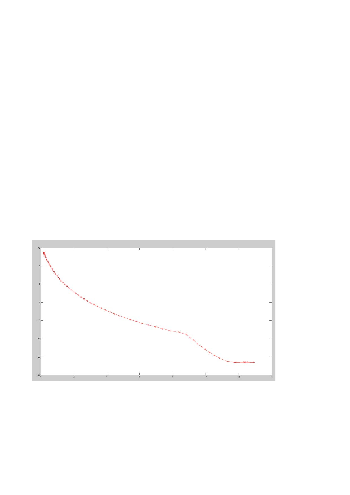
VCA
A VC A, o r voltage-controlled amplifier , is an amplif ier that var ies its gain depending on a c ont rol
voltage, such that the input voltage determines the output voltage. The TG12345 includes a VCAbased compressor. However, whereas most VCA-based compressors only attenuate the signal
(voltage in > voltage out) , the TG12345’s c om pres s or als o am plifies it (upwards compression) at
very lo w levels (below 1.5 V).
In the graph above, the Y axis represents the amount of amplification or attenuation in dB, while the
X ax i s r epres ents the input to the VCA in volts ( 0 dBfs = 13.875 V). As the graph s hows , s ignals
below 1.5 V are boosted while signals above 1.5 V are attenuated. The V CA input is triggered by
the feedback signal through the sidec hain.
Waves / A bbey Road TG 12345
User Guide
Page 6
6
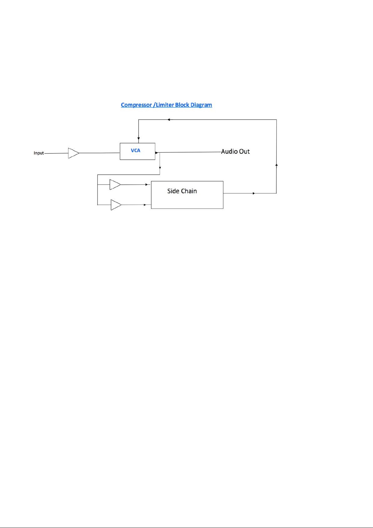
Feedback Com pression
The signal ent ering the compressor is sent to the VCA. The output of the VCA is then split: one copy
goes to the output, while the other is fed back to the VCA via a sidechain circuit. See the image
below:
Sidechain High Pass (SC-HP)
As explained in the Feedbac k C om pres s ion s ec tion above, the input signal is fed to back to the
VCA. Gener ally, the m or e ener gy you have in the s idec hain, the m ore com pr es s ion you get; but if
you apply a high-pass filter to remove low energy from the signal, the result is less energy when
low-frequency energy is present, hence less compression. In the case of a bass guitar, for example,
the abundance of low energy entails lots of compression; but if a high-pass filter is applied on the
sidechain, the VCA will identify less energy on the low bass notes than there is in the actual input
signal and will therefore attenuate the signal less, allowing more low frequency.
Sidechain V oltage
The sidechain section of the TG12345 converts the signal from AC to DC, with the VCA controlled
via the DC current. The higher the DC current, the more compression you get. The sidechain
voltage can range from a couple of mV to 15 V. The amount of compression for each volt is
represented in the VCA graph above.
Waves / A bbey Road TG 12345
User Guide
Page 7

7
TG12345 Cassettes
The original TG12345 desk included three main sections, or three types of “cassettes” (technically
there were six types of cassettes, but only three were significant sound-wise; the other three were
utility c ass ettes):
1. Microphone Cassette: This section had the mic preamp, an EQ (treble + bass) section, a
dynamics section, sends + returns, a spread, a pan pot, and faders. Each cassette was
actually a stereo channel, with the option of summing the signal to mono. In TG12345 MK II,
the treble EQ was replaced with a presence EQ and the spreader was removed.
2. Group Cassette: There w ere two group c as s ettes , eac h c ontaining tw o subgroups . Any of
the microphone cassettes c ould be r outed to a group c as s ette, and multiple c hannels rout ed
from the mic cassette to the group cassette could be cont rolled thr ough the group channel.
The group cassette had another dynamics section as well as a presence control (in the
TG12345 MK II, this pres enc e c ontr ol replaced the treble EQ ).
3. Main Cassette: The TG12345 had five main cas s ettes : four feeding the t ape machine (each
was a stereo cassette, for a total of eight tracks), and one for the aux stereo outputs. Each
main cassette had another presence EQ section to adjust the final output to the tape.
If you review the r outing on the TG12345 plugin, you will s ee that you can ac hieve any s ignal flow
within the console using two instances of the plugin. A signal flow simulating a mic-cassette-togroup-c as s ette flow on the TG12345 MK I can be ac hieved using just one instance (EQ>Dyn>Pres).
1.5 Components
WaveShell technology enables us to split Waves processors into smaller plugins, which we call
components. Having a choice of components for a particular processor gives you the flexibility to
choose the configuration best suited to your material. TG12345 includes the f ollowing c om ponent s :
o TG12345 Mono
o TG12345 Stereo
Waves / A bbey Road TG 12345
User Guide
Page 8

8
Chapter 2 – Interface and Controls
2.1 I nterf ace
Waves/Abbey Road TG 12345
User Guide
Page 9

9
2.2 Cont rols
Input
Increases or decreases the gain of the signal.
Range: -24 dB to 24 dB
Default: 0 dB
Routing
Allows you to order the signal flow — EQ (Treble + Bass), Presence, Dynamics — in one of
three w ays:
• EQ>Dyn>Pres – EQ first, then Dynamics, then Presence
• Dyn>EQ>Pres – Dynamics first, then EQ, then Pres enc e
• EQ>Pres>Dyn – EQ first, then Presence, then Dynamics
Default: EQ > Pres > D yn
Dynamics
Mode
Allows you to choos e between three dynamic modes:
• Out – In this mode, the Dynamics section is bypassed.
• Compressor – Compressor mode (2:1), with attack fixed to 1 ms.
• Limiter – Limiter mode (7:1) with attack fixed to 1 ms.
Default: Out
Hold
Sets a constant DC v oltage for the sidechain that feeds the V CA (for more information on
VCA, see the Concepts and Terminology section on p. 5 above). This constant voltage
causes a fixed amount of attenuation throughout the signal. When the input voltage that
reaches the sidechain is greater than the voltage set by the Hold control, the plugin’s
simulated diode is breached and VCA is triggered by a changing D C voltage, c aus ing t he
gain change to vary according to the VCA characteristics. When the input voltage is lower
than the voltage set by the Hold control, the amount of attenuation is once again constant.
This control is the only way for you to narrow the VCA’s gain c hange range.
The way to use the Hold control is this: set the meter to GR, change the Hold level until you
get the overall amount of compression you want, then make up for the gain loss using the
Waves/Abbey Road TG 12345
User Guide
Page 10

10
output faders . M any compressors operate by linking the hold control to the output faders (the
thres hold), but the TG12345 is unique in keeping them separ ate.
Range: 0–100
Default: 0
Recovery
Sets the release time, with six states for each dynamic mode.
Range: 100 ms, 250 ms, 500 ms, 1 sec, 2 sec, 5 sec.
Default: 100m s
SC-HP
Applies a high-pass filter on the sidechain signal at around 90 Hz, resulting in les s
compression on the low end.
Range: On, Off
Default: Off
Mix
Controls the balance between the compressed and uncompressed signal.
Range: 0% to 100% (0.1% increments)
Default: 100%
EQ
Treble
Boost: Bell filter fixed at 5 kHz
Cut: Shelf fixed at 10 kHz
Range: -10 dB to 10 dB
Default: 0 dB
Presence (kHz)
Bell filter controls the center frequency of the presence filter.
Range: 500 Hz to 10 kHz (continuous)
Default: 1.8 kHz
Pr es enc e ( dB)
Boosts/cuts the presence filter.
Range: -10 dB to 10 dB
Default: 0 dB
Waves / A bbey Road TG 12345
User Guide
Page 11

11
Bass
Low shelf filter fixed at 50 Hz.
Range: -10 dB to 10 dB
Default: 0 dB
EQ Bypass
Bypasses the entire EQ section.
Range: On/Off
Default: Off
Master Section
Phase
Inverts the phase of the signal (one per channel).
Range: On/Off
Default: Off
Channel Selector
Two channels of the original TG12345 desk have been modeled: Channels 1 and 2.
• Mono: Select Channel 1 or 2
• Stereo: Select Channel 1 or 2 for L, R, or both
• L default: Channel 1
• R default: Channel 2
Note: To keep your stereo image as close as possible to your input, select the same
channel for both L and R.
Drive
Controls the amount of drive added to the processed signal.
Range: Off to 100
Default: Off
Noise
Controls the amount of noise and hum added to the processed signal.
Range: Off to 100
Default: Off
Waves / A bbey Road TG 12345
User Guide
Page 12

12
Spread (Stereo Com ponent Only)
Contr ols the balance bet ween the mid and s ides by changing the level of the s ides only,
while the level of the m id remains constant. This feature is available in all cassette modes,
not just in MS. The spread is very similar to an MS matrix; it is faithful to the plugin’s analog
origins, however, in that the encoding and decoding of the matrix do not cancel each other
perfectly, giving the spread its distinctive vintage c harac ter .
Range: -12 dB to 6 dB (0.1 dB increments)
Default: 0
Monitor (Stereo Com ponent Only)
Selects the s ourc e of the monitor output.
• Left – Left output is sent to both sides (in MS Mode this monitors the mid)
• Mono – Left and Right outputs are summed to mono and trimmed down by 6 dB
• Stereo – Stereo mode
• Right - Right output is sent to both sides (in MS Mode, this monitors the sides)
Default: Ster eo
Output
Two faders (one per channel) that control output gain after processing.
Range: -48 dB to 24 dB
Default: 0 dB
Metering
VU Meter
Displays input, output and gain reduc tion levels, depending on your selection.
Range IN/OUT: -20 VU to 3 VU
Range GR: -20 VU to 9 VU
Pea k Met er
Displays signal peak output level.
Range IN/OUT: -20 dBfs to 0 dBfs
Range GR: -20 dBfs to 9 dBfs
Waves / A bbey Road TG 12345
User Guide
Page 13

13
VU Meter – Headroom Calibration Control
The meter’s headroom calibration default is set to 18 dB headroom. The meter can be
adjusted using the little screw underneath to provide a headroom of 8 to 24 dB (or -8 to -24
dB), where X dBfs = 0 VU.
Range: 8 dB to 24 dB / -8 dB to -24 dB
Default: 18 dB
Meter I /O
The meter I/O lets you select from three monitoring modes:
GR: Show s the total amount of gain reduc tion/inc r eas e.
IN: Shows the input signal level post-input control, so that any change in the input is
reflected in the meter.
OUT: Shows the output level of the plugin post-output control, so that any change in the
output is reflected in the meter.
Please note: Some constant amplification factors are not reflected in the GR meter because
they are fixed and not s ignal-dependent. This is why what you see on the GR meter will not
necessarily reflect what you are hearing.
Range: GR / IN / OUT
Default: IN
Clip Indicator
Indicates peak cli pping.
Waves / A bbey Road TG 12345
User Guide
Page 14

14
Chapter 3 – The Wav eSystem
3.1 The WaveSystem Too lbar
All Waves plugins f eature t he WaveSys tem toolbar , which takes care of most of the administrative
functions you will encounter while working with your Waves software. The features of the
WaveSystem toolbar are the same on practically all Waves plugins, so familiarity with its features
will be helpful whichever plugin you are using.
Toolbar Functions
Opens the plugin About box
Undo Undoes the last 32 actions
Redo Redoes the last 32 undone actions
Setup A /B Toggles between two presets, useful for comparison of parameter settings
L/R Arrows Move to the previous or next preset
Copy A→B Copies the current settings to the second preset register
Load Recalls presets from file
Save Saves presets in the Waves file formats
? Opens the PD F m anual for the plugin you are using
3.2 Preset Handling
Preset Types
Factor y Pre se t s are permanent presets in the Load menu. Factory presets cannot be overwritten or
deleted. When applicable, different component plugins may have different factory presets.
User Presets are your favorite settings of the plugin saved as a preset in the Load menu, under
‘User Presets’. User P res ets c an be overw ri tten and deleted.
Setup Files may contain more than one preset. For example, a single file can contain all the
pres ets for a ses s ion. W hen you open a S etup File, all its s etups becom e part of your Load pop-up
menu for fast access. This can be particularly useful with multiple instances of a plugin in a single
ses s ion. B y saving all the s ett ings you c r eate into a s ingle Setup File, they can all be quickly
available for every instance of that plugin.
Waves / A bbey Road TG 12345
User Guide
Page 15

15
Loading Presets and Setups
Click on the Load button to see the Load pop-up m enu. The m enu is divided int o four sec tions . If a
section is not currently available it will not appear in the Load pop-up m enu.
Open Preset File… Select to open any setup or preset file, whether from the Library or your own
creations.
‘Filename.xps’: Displays any currently loaded Setup File and its presets.
Factor y Pre se t s: Displays the default Factory Presets.
User Presets: Displays any loaded User Presets.
Saving Presets and Setups
Click on the Save button to see the Save pop-up menu. Four options are available. If an option is
not currently available it will be grayed out and inaccessible.
Save to New File… Select this to start a new Setup file. There are two prompts -
first for the setup filename, then for the preset name. You must
provide a name for both the setup file and the preset. Click OK
(ENTER) to complete the save. It is a good idea to create a
folder in which to save several setup files for a project.
Save ‘File Nam e’ – “Pr es et N ame” Overwrites t he s ettings of the loaded preset (whether a Us er
Preset or a preset from a Setup File) with the current settings.
If a Setup File is c urr ently loaded, the name of the Setup File is
displayed fol lowed by the name of the pres et its el f. If a User
Preset is loaded, its name is displayed.
Save to ‘File Nam e’ A s… Saves the current settings as a new preset into the Setup file
that is open (if one is not open, the option is grayed out). You
will be prompted to give the preset a name.
Put into Preset Menu A s … Save the current settings into a User Preset that will always be
in your Load m enu (until deleted) . You will be pr om pted to give
this preset a name. User Presets are stored in the plugin’s
preference file.
Waves / A bbey Road TG 12345
User Guide
Page 16

16
Deleting Presets
You may delete User Presets and presets within a Setup File. Factory Presets and Setup Library
files cannot be deleted or overwritten.
1. Hold the Command (M ac)/Control (PC) key down.
2. Click-and-hold the Load button to see the pop-up m enu.
3. While still holding the Command/Control key, select the preset or setup to delete.
4. A confirmation box will appear, allowing you to cancel or ‘OK’ the deletion.
A/B Comparison and C opying
The Setup A/Setup B button may be clicked to compare two settings. If you load a preset in the
Setup B position, this will not affect the preset loaded into the Setup A position, and vice-versa.
If you want to slightly modify the settings in Setup A, you can copy them to Setup B by clicking on
the Copy to B button, then alter Setup A and compare with the original Setup B .
The name of the current setup will be shown in the title bar (on platforms which support it), and will
switch as y ou change from Setup A to Setup B.
Note: an asterisk will be added to the preset name when a change is made to the preset.
3.3 Interf ace Controls
Controls can be in one of three states:
1. Not Selected where the control is not the target of any user entry
2. Selected where the control is the target of mouse control entry only
3. Selected and A ctive where the control is the target for both mous e and keyboard ent ry
Toggle Buttons
Toggle buttons display the state of a control, and allow switching between two or more states.
Single-click to change the control’s state. Some toggle buttons have a text display which updates
Waves / A bbey Road TG 12345
User Guide
Page 17

17
with the current setting, and others (bypass, solo, or monitoring toggles) illuminate when the control
is active.
Some plugins have link buttons between a pair of toggle but tons , allowing cl ic k-and-drag
adjustment while retaining the offset between the controls.
Va lue W indow Buttons
Value window s dis play the value of a contr ol and allow click-and-drag adjustment, or direct
control via the key board.
Using the m ouse, click-and-drag on the value window to adjust. Some value windows
support left/right, some up/down (as you hover over a button, arrow s w ill appear to let you
know which direction of movement that button supports). You may also use your mousewheel to adjust parameter values.
Using the a rrow keys, click once with mouse to select the button, and then use up/down –
left/right (depending on the direction supported by that button) to move in the smallest
incremental steps across the button’s range (holding down the arrow keys will move faster
through the range).
Using key entry, double click on the button to open the value window, and directly enter the
value from your keyboard. If you enter an out of range number, the button stays selected but
remains at the current setting (system beeps if system sounds are on).
Some plugins have link buttons between a pair of value w indows , allow ing c lic k-and-drag
adjustment while retaining the offset between the controls.
Sliders
Click or scroll the mouse-wheel on the slider itself or anywhere within the sliders track. The
numerical value of the slider settings is displayed in a hover window above the slider path.
Hover Box
Hovering boxes will appear and display the control value when hovering with the mouse over the
control.
Multiple Control Selection
One of the most powerful features of the WaveSystem is the ability to select and adjust multiple
controls simultaneously. Using the mouse, drag-select the desired group of buttons or graphic
cont rols by clic king and holding at a point outs ide the cont rols , and forming a rectangle that includes
Waves / A bbey Road TG 12345
User Guide
Page 18

18
the controls you wish to adjust. Alternatively, press and hold Shift while clicking the mouse on any
control you wish to link. This method is useful when you want to select two or more controls that are
not adjacent to one another.
TAB Functions
TAB moves the ‘selected’ status to the next control, with shift-TAB moving in the reverse direction.
Additionally, the Mac has an option-TA B function for ‘down’ movement and shift-option-TAB for ‘up’
movement where applicable. If you have several Value Window Buttons selected, TAB functions will
take you through the selec ted contr ols only.
Hitting Esc or Return will return the 'focus' to the DAW application.
3.4 W aves Pref eren ce s ( Pro Tool s DAE only)
When launching Pro Tools, hold Shift to view the Waves plugin Prefer enc es window . The following
options are available:
• Don't use AudioSuite plugins
• Don’t use RTA S plugins
• Rescan all plugins
• HU I control surface support (low resolution)
• Enable s ingle-click text entry
Waves / A bbey Road TG 12345
User Guide
 Loading...