

Page 1
Preliminary
MX5000A Development System Manual
1 System Overview
The MX5000A Development System allows manufacturers to easily evaluate and prototype
system improvements by adding MaxxAudio psycho-acoustic processing to existing audio
systems. The MX5000A Development System contains the small MX5000A Prototype
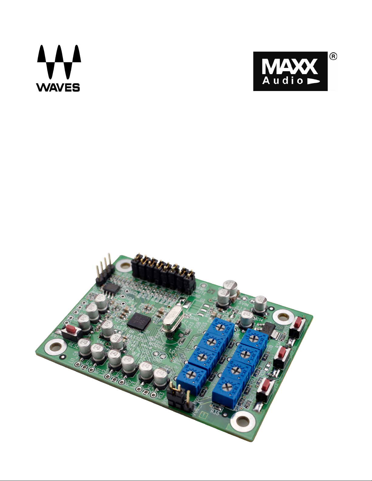
Module as shown in Figure 1, with simple connections for analog stereo input and output.
The MX5000A Development System also includes a Telos USB to I2C emulator with a
sophisticated PC graphic user interface. It also can be used without any external controls by
using the on-board potentiometers as audio controls.
.
Figure 1. MX5000 Prototyping Module
MX5000A Development System January 2007
Page 2

Preliminary
2 Input/Output and Power Connections
Connect Inputs, Outputs, Power and Ground as described below. Please see Figures 2 and
3 for additional illustrations.
Connect Inputs
• Three sets of stereo inputs are provided. Located on the bottom edge of the PCB,
these are labeled as LI1/RI1, LI2/RI2, and LI3/RI3. Each stereo pair uses a common
ground, labeled “G”, located between the left/right inputs.
• Connect stereo inputs and ground(s) as needed.
• All analog inputs support 4Vpp maximum input levels.
Connect Outputs
• Connect stereo outputs, labeled LO and RO, on the left side of the PCB. LO and RO
use a common ground labeled GND between the LO and RO connection points.
• Connect subwoofer output (labeled SUB) and ground (labeled GND) if needed.
• All analog output support 4Vpp maximum input levels.
Connect Power Supply and Ground
• Provide an external 5.0V DC and ground to the 5VIN and GND pins to the upper right
corner of the PCB. This needs to be a well regulated analog supply, since this voltage
is connected directly to the analog_Vcc of the device without additional regulation.
MX5000A Development System January 2007
Page 3
Preliminary
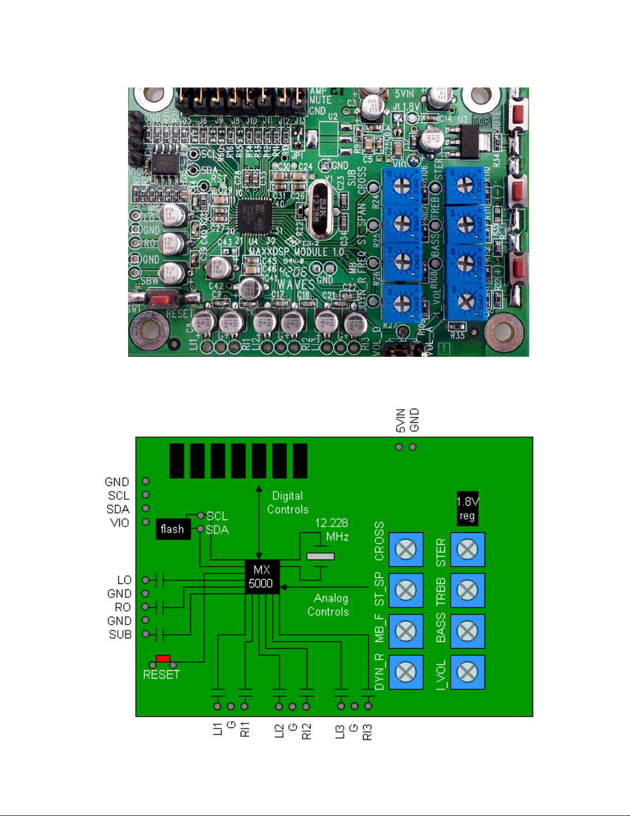
Figure 2. MX5000 Prototype Module Close-up
Figure 3. Connections for MX5000 Prototype Module
MX5000A Development System January 2007
Page 4

Preliminary
3 Controls
The MX5000 Prototyping Module supports two different control options.
a) I2C Slave Mode
b) I2C Host Mode
3.1 I2C Slave Mode Controls
In addition to the MX5000 Prototyping Module, the MX5000A Development System is
supplied with a Telos USB to I2C Emulator. www.telos.info Waves recommends the Connii
MM or Connii which enables connection to the USB port of a Windows XP PC along with
associated software. A special cable is also provided to connect between the Telos emulator
and the 4pin I2C header on the MX5000A Prototyping Module. These three items are shown
in Figure 4.
Figure 4. MX5000A Development System Hardware Components
MX5000A Development System January 2007
Page 5

Preliminary
3.2 Graphic User Interface
The GUI for the MX5000 Prototyping Module is shown in Figure 5.
Figure 5. MX5000A GUI
MX5000A Development System January 2007
Page 6

Preliminary
3.3 Digital Audio Input/Ouput
For digital audio I/O, the system supports three stereo inputs and two stereo outputs as
shown in Table 1. All inputs and outputs are synchronous with shared clock and synch pins.
The digital audio input/output is supported only in I2C Slave Mode of the MX5000A.
Table 1. Digital Audio Input/Output Connections
Clock
Synch
Digital Input0
Digital Input1
Digital Input2
Digital Output0
Digital Output1
PIN NUMBER GPIO
1 0 Pin 2 of J13
2 1 Pin 2 of J12
3 2 Pin 2 of J11
4 3 Pin 2 of J10
5 4 Pin 2 of J8
8 5 Pin 2 of J9
9 6 Pin 2 of J6
CONNECTION ON
THE BOARD
* pin 2 of Ji (were i=6, 5,...13) located on the edge of the board. See Figure 6.
Please note: There are pull-up resistors connected to those pins. You may decide to leave
them as is or to disconnect them, depending on your system.
The list of those resistors:
Clock
Synch
Digital Input0
Digital Input1
Digital Input2
Digital Output0
Digital Output1
Pull-up to VIO
resistor
R10 0 Pin 2 of J13
R11 1 Pin 2 of J12
R12 2 Pin 2 of J11
R13 3 Pin 2 of J10
R14 4 Pin 2 of J8
R15 5 Pin 2 of J9
R16 6 Pin 2 of J6
GPIO
MX5000A Development System January 2007
Page 7

Preliminary
Figure 6. MX5000A Prototyping Module Layout
Full schematics, bill of materials, and layout files for this system is available to customers.
MX5000A Development System January 2007
Page 8

Preliminary
3.4 I2C Host Mode Controls
In I2C Host Mode, the MX5000 will read audio parameters from the external serial flash ROM
after reset. After reset, the system will continuously monitor the value of external analog
control pins for real-time audio controls. These pins are connected to eight potentiometers
on the MX5000 Prototyping Module for OEM presets and user controls, which are
summarized in Table 2.
The MX5000 will support most of its major functions in I2C Host mode. Some functions, like
MaxxEQ, require modifying the flash ROM for static customized parameters, or can be used
fully dynamically (and clicklessly) in I2C Slave Mode.
Table 2. Analog Control Potentiometers
Potentiometer
Label
I_VOL MaxxVolume ™
Function Full Counterclock-
Full Clockwise
wise Value
Mute / -80dB + 20dB
Value
Gain
BASS MaxxBass ®
Intensity
TREB MaxxTreble ™
Intensity
STER MaxxStereo ™
Intensity
DYN_R MaxxVolume ™
Bypass
100% intensity
MaxxBass
Bypass
100% intensity
MaxxTreble
Bypass
100% intensity
MaxxStereo
80dB 20dB
Dynamic Range
MB_FREQ MaxxBass ®
20 Hz 320 Hz
Frequency
ST_SP MaxxStereo ™
5 degrees 30s degrees
Speaker Span
CROSS Subwoofer Crossover
20 Hz 320 Hz
(active only when
subwoofer out
enabled)
MX5000A Development System January 2007
Page 9

Preliminary
5 Ordering Part Numbers
MX5000ADS
For MX5000A Development System
Includes:
MX5000A Prototyping Module (MX5000APM)
Telos Connii or Connii MM with software
Waves Control GUI software
4 wire cable – Telos connector to I2C header
Note: ‘A’ in MX5000A refers to hardware/software version of the MX5000.
MX5000APM
For MX5000A Prototyping Module
Includes:
MX5000A Prototyping Module PCB only
Note: ‘A’ in MX5000A refers to hardware/software version of the MX5000.
6 Trademark Notice
MaxxBass, MaxxAudio, MaxxVolume, MaxxTreble, MaxxEQ, MaxxStereo are trademarks or
registered trademarks of Waves Audio Ltd. in the US and other countries.
MX5000A Development System January 2007
 Loading...