

Page 1
MV360˚
User Manual
MV360˚ User Manual 1
Page 2

Table of Contents
Chapter 1 – Introduction ................................................................................................3
1.1 Welcome..................................................................................................................3
1.2 Product Overview....................................................................................................3
1.3 Concepts and Terminology......................................................................................3
High Level Compressor .............................................................................................4
Link Modes.................................................................................................................4
Dither .........................................................................................................................4
1.4 Components............................................................................................................5
Chapter 2 – Quickstart Guide ........................................................................................6
Chapter 3 – Interface and Controls ...............................................................................7
3.1 Interface...................................................................................................................7
3.2 Controls...................................................................................................................8
Low Threshold...............................................................................................................8
High Threshold..............................................................................................................8
Low Volume...................................................................................................................8
Master Fader Controls...............................................................................................9
Link Mode Selector..................................................................................................10
Cut (Attenuation) / Boost Meters..............................................................................10
Chapter 4 – The WaveSystem......................................................................................11
4.1 The WaveSystem Toolbar.....................................................................................11
Toolbar Functions....................................................................................................11
4.2 Preset Handling.....................................................................................................11
Preset Types ............................................................................................................11
Loading Presets and Setups....................................................................................12
Saving Presets and Setups......................................................................................12
Deleting Presets.......................................................................................................13
A/B Comparison and Copying..................................................................................13
4.3 Interface Controls..................................................................................................13
Toggle Buttons.........................................................................................................13
Value Window Buttons.............................................................................................14
Multiple Selection of Controls ..................................................................................14
TAB Functions .........................................................................................................14
Appendix A –Link Modes .............................................................................................15
All Linked.....................................................................................................................15
5 Linked | Sub..............................................................................................................15
Front | Rear | Sub........................................................................................................15
Center | Quad | Sub.....................................................................................................16
Center | Front LR | Rear (LFE Is Bypassed)................................................................16
MV360˚ User Manual 2
Page 3
Chapter 1 – Introduction
1.1 Welcome
Thank you for choosing Waves! In order to get the most out of your Waves processor,
please take the time to read through this manual.
In conjunction, we also suggest that you become familiar with
There you will find an extensive
Installation guides, new Software Updates, and current information on Authorization
and
Registration.
By signing up at www.wavesupport.net, you will receive personalized information on
your registered products, reminders when updates are available, and information on
your authorization status.
Answer Base, the latest Tech Specs, detailed
1.2 Product Overview
MV360 is a dual function dynamics processor for 5.0 and 5.1 Surround sound
applications. It provides six discrete channels of low level and high level compression.
www.wavesupport.net.
1.3 Concepts and Terminology
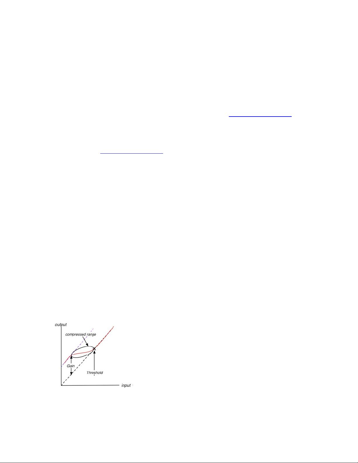
Low Level Compressor
Low Level Compression can be explained in simple terms as the opposite of
standard or high level compression. In a standard compression setting, any signal
above the set threshold gets compressed and attenuated.
With the MV360˚ Low Level Compression function, any signal below the set
threshold gets compressed upward, resulting in increased gain. The dynamic range
is thus compressed, pushing low levels up while leaving high levels as they were.
MV360˚ User Manual 3
Page 4

High Level Compressor
The MV360˚ High Level Compression function is comprised of compression with
automatic makeup gain and output level control.
The Compressor function is similar to that of Waves Renaissance Vox. The compressor
is controlled by the Threshold fader, which sets the amount of desired dynamic range
compression. An automatic gain makeup function compensates for gain reduction
resulting from the applied compression.
Link Modes
MV360° offers 5 Link Modes which let you use up to 3 separate sidechains that address
the most commonly used sound stage disciplines.
All Linked
In this mode, all channels are linked, maintaining the balance between the 5
main channels and the LFE channel.
5 Linked | Sub
This mode fully preserves the surround image, but does not attenuate/boost the
directional channels in conjunction with peaks in the LFE channel.
Front | Rear | Sub
This mode is useful in situations when rear channel ambience and effects don’t
require attenuation/boost in conjunction with front channel music or dialog.
Center | Quad | Sub
This mode offers independent dynamic control over dialog, overall surround
image, and LFE channel.
Center | Front LR | Rear (LFE Is Bypassed)
This mode offers the most control over the surround image, and its functionality
is similar to that of three independent dynamics processors.
Dither
MV360˚ automatically applies dither, which compensates for digital quantization
errors.
MV360˚ User Manual 4
Page 5

1.4 Components
WaveShell technology enables us to split Waves processors into smaller plug-ins, which
we call components. Having a choice of components for a particular processor gives
you the flexibility to choose the configuration best suited to your material.
o MV360 5.0 to 5.0
o MV360 5.1 to 5.1
MV360˚ User Manual 5
Page 6

Chapter 2 – Quickstart Guide
Set link to Front/Rear/LFE
Start on the Left side (Threshold):
- Use the bottom (single arrow) Low Level Master Fader to set the global
Low Level Threshold
- Use top (single arrow) High Level Master Fader to set the global
High Level Threshold
- Use the middle cut/boost meters to monitor the amount of gain cut and boost
applied per link group
On the Right side (Volume)
- Use the top volume faders per link color to trim the High Level
Compression makeup gain
- Use bottom volume faders per link color to trim the Low Level
Compression makeup gain
MV360˚ User Manual 6
Page 7

Chapter 3 – Interface and Controls
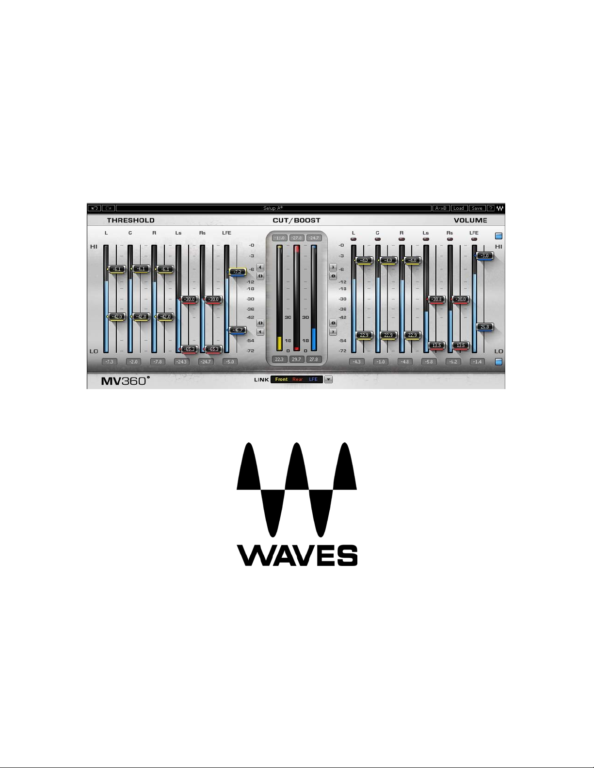
3.1 Interface
MV360˚ User Manual 7
Page 8

3.2 Controls
Low Threshold
Sets the low level compression threshold. Compression is applied to signals below this
threshold.
Range:
-72 to -36 dBFS
High Threshold
Sets the high level compression threshold. Compression is applied to signals above this
threshold.
Range:
0 to -30 dBFS
Low Volume
Controls the amount of makeup gain applied to the compressed low level signal.
Range:
0 to +30 dB
High Volume
Trims the amount of automatic gain compensation applied to the compressed high level
signal.
Range:
0 to -30 dBFS
High Level Compression On/Off
Low Level Compression On/Off
MV360˚ User Manual 8
Page 9

Master Fader Controls
High Level Compression Master
Moves all High Level faders (Threshold and Volume) by the same value, relative to each
of their current positions.
Range:
0 to ±30 dB
Low Level Compression Master
Moves all Low Level faders (Threshold and Volume) by the same value, relative to each
of their current positions.
Range:
0 to ±30 dB
High Level Volume Master
Moves all High Level Volume faders by the same value, relative to each of their current
positions.
Range:
0 to ±30 dB
Low Level Volume Master
Moves all Low Level Volume faders by the same value, relative to each of their current
positions.
Range:
0 to ±30 dB
High Level Threshold Master
Moves all High Level Threshold faders by the same value, relative to each of their
current positions.
Range:
0 to ±30 dB
MV360˚ User Manual 9
Page 10

Low Level Threshold Master
Moves all Low Level Threshold faders by the same value, relative to each of their current
positions.
Range:
0 to ±30 dB
Link Mode Selector
The Link Mode Selector allows the selection of one of five link modes. Each Link Mode
determines which channels are linked, both in the interface controls and with regard to
the dynamic detector sidechain and compression.
Link Mode selection affects the colors of both low and high level compression threshold
and gain controls, which provides per channel indication of link status.
All Linked
5 Linked | Sub
Front | Rear | Sub
Center | Quad | Sub
Center | Front LR | Rear (LFE Is Bypassed)
Cut (Attenuation) / Boost Meters
Display the amount of gain cut and/or boost for each of the 3 possible Link groups.
Attenuation is displayed from the top down.
Boost is displayed from the bottom up.
Each of the 3 meters (yellow, red, blue) corresponds to a Link Group, which are
indicated in the text box located below the meters.
Numeric indicators which display the maximum attenuation are located above the
meters; maximum gain is displayed below the meters. Reset these values by clicking
anywhere on the meter.
The meters display up to -30dB of attenuation, and +30 dB of gain boost.
MV360˚ User Manual 10
Page 11

Chapter 4 – The WaveSystem
4.1 The WaveSystem Toolbar
All Waves processors feature the WaveSystem toolbar which takes care of most
administrative functions you will encounter while working with your Waves software. The
features of the WaveSystem toolbar are the same on practically all Waves processors,
so familiarity with its features will be helpful whichever processor you are using.
Toolbar Functions
Undo Undoes the last 32 actions.
Redo Redoes the last 32 undone actions.
Setup A/B Toggles between two presets for comparison of different parameter
settings.
Copy A->B Copies the current settings to the second preset register.
Load Recalls presets from file.
Save Saves presets in the Waves file formats.
? Opens the manual for the processor you are using.
4.2 Preset Handling
Preset Types
Factory Presets are permanent presets in the Load menu. Factory presets cannot be
over-written or deleted. When applicable, different component plug-ins may have
different factory presets.
User Presets are your favorite settings of the plug-in saved as a preset in the Load
menu, under ‘User Presets’. User Presets can be over-written and deleted.
Setup Files may contain more than one preset. For example, a single file can contain all
the presets for a session. When you open a Setup File, all its setups become part of
your Load pop-up menu for fast access. This can be particularly useful with multiple
instances of a plug-in in a single session. By saving all the settings you create into a
single Setup File, they can all be quickly available for every instance of that plug-in.
MV360˚ User Manual 11
Page 12

Loading Presets and Setups
Click-and-hold on the Load button to see the Load pop-up menu. The menu is divided
into four sections. If a section is not currently available it will not appear in the Load popup menu.
Open Preset File… Select to open any setup or preset file, whether from the Library or
your own creations.
‘Filename.xps’: Displays any currently loaded Setup File and its presets.
Factory Presets: Displays the default Factory Presets.
User Presets: Displays any loaded User Presets.
Saving Presets and Setups
Click-and-hold on the Save button to see the Save pop-up menu. Four options are
available. If an option is not currently available it will be grayed out and inaccessible.
Save to New File… Select this to start a new Setup file. There are two
prompts - first for the setup filename, then for the
preset name. You must provide a name for both the
setup file and the preset. Click OK (ENTER) to
complete the save. It is a good idea to create a
folder in which to save several setup files for a
project.
Save ‘File Name’ – “Preset Name” Overwrites the settings of the loaded preset
(whether a User Preset or a preset from a Setup
File) with the current settings. If a Setup File is
currently loaded, the name of the Setup File is
displayed followed by the name of the preset itself.
If a User Preset is loaded, its name is displayed.
Save to ‘File Name’ As… Saves the current settings as a new preset into the
Setup file that is open (if one is not open, the option
is grayed out). You will be prompted to give the
preset a name.
Put into Preset Menu As… Save the current settings into a User Preset that
will always be in your Load menu (until deleted).
You will be prompted to give this preset a name.
User Presets are stored in the plug-in’s preference
file.
MV360˚ User Manual 12
Page 13

Deleting Presets
You may delete User Presets and presets within a Setup File. Factory Presets and
Setup Library files cannot be deleted or overwritten.
1. Hold the Command (Mac)/Control (PC) key down.
2. Click-and-hold the Load button to see the pop-up menu.
3. While still holding the Command/Control key, select the preset or setup to delete.
4. A confirmation box will appear, allowing you to cancel or ‘OK’ the deletion.
A/B Comparison and Copying
The Setup A/Setup B button may be clicked to compare two settings. If you load a preset
in the Setup B position, this will not affect the preset loaded into the Setup A position,
and vice-versa.
If you want to slightly modify the settings in Setup A, you can copy them to Setup B by
clicking on the Copy to B button, then alter Setup A and compare with the original Setup
B.
The name of the current setup will be shown in the title bar (on platforms which support
it), and will switch as you change from Setup A to Setup B.
Note: an asterisk will be added to the preset name when a change is made to the preset.
4.3 Interface Controls
Controls can be in one of three states:
•
Not Selected where the control is not the target of any user entry
Selected where the control is the target of mouse control entry only
•
Selected and Active where the control is the target for both mouse and
•
keyboard entry
Toggle Buttons
Toggle buttons display the state of a control, and allow switching between two or more
states.
display which updates with the current setting, and others (bypass, solo, or monitoring
toggles) illuminate when the control is active.
Some processors have
and-drag adjustment while retaining the offset between the controls.
Single-click to change the control’s state. Some toggle buttons have a text
link buttons between a pair of toggle buttons, allowing click-
MV360˚ User Manual 13
Page 14

Value Window Buttons
Value windows display the value of a control and allow click-and-drag adjustment, or
direct control via the keyboard.
•
Using the mouse, click-and-drag on the value window to adjust. Some value
windows support left/right, some up/down (as you hover over a button, arrows
will appear to let you know which direction of movement that button supports).
•
Using the arrow keys, click once with mouse to select the button, and then use
up/down – left/right (depending on the direction supported by that button) to
move in the smallest incremental steps across the button’s range (holding down
the arrow keys will move faster through the range).
•
Using key entry, double click on the button to open the value window, and
directly enter the value from your keyboard. If you enter an out of range number,
the button stays selected but remains at the current setting (system beeps? If
system sounds are on?)
Some processors have
and-drag adjustment while retaining the offset between the controls.
link buttons between a pair of value windows, allowing click-
Multiple Selection of Controls
One of the most powerful features of the WaveSystem is the ability to select and adjust
many controls at the same time. Using the mouse, simply drag-select the desired group
of button or graphic controls by clicking and holding at a point outside the controls and
forming a rectangle to include the controls you wish to adjust. Alternatively, you can hold
down Shift while clicking the mouse on any control you wish to link. This second method
is useful when you want to select two (or more) controls that are separated on the GUI
by other controls you do not wish to select.
TAB Functions
TAB moves the ‘selected’ status to the next control, with shift-TAB moving in the reverse
direction.
Additionally, the Mac has an option-TAB function for ‘down’ movement and shift-optionTAB for ‘up’ movement where applicable.
If you have several Value Window Buttons selected, TAB functions will take you through
the selected controls only.
MV360˚ User Manual 14
Page 15

Appendix A –Link Modes
When applying dynamics to a stereo mix, stereo imaging is preserved by applying
identical gain attenuation/boost to both the left and right channels. This is known as
linked dynamics processing. The dynamics detector works on an L+R linked sidechain,
applying the same gain attenuation/boost to both left and right channels, preserving their
relative levels and intended stereo image.
In Surround, there are different schools of thought with regard to sound stage imaging.
MV360° offers 5 Link Modes which let you use up to 3 separate sidechains that address
the most commonly used sound stage disciplines.
All Linked
In this mode, all channels are linked. Uniform attenuation/boost is applied, preserving
the complete surround image, and maintaining the balance between the 5 main
channels and the LFE channel.
5 Linked | Sub
In this mode, a separate sidechain is dedicated to the LFE (Subwoofer) channel. The
sound stage is divided into the directional (main) 5-channel sound field, and the nondirectional LFE channel.
This mode fully preserves the surround image, but does not attenuate/boost the
directional channels in conjunction with peaks in the LFE channel.
Front | Rear | Sub
This mode uses 3 separate sidechains:
The first sidechain links Left, Center and Right channels.
The second sidechain links Rear Left and Rear Right channels.
The third sidechain is dedicated to the LFE channel.
This mode is useful in situations when rear channel ambience and effects don’t require
attenuation/boost in conjunction with front channel music or dialog.
MV360˚ User Manual 15
Page 16

Center | Quad | Sub
This mode uses 3 separate sidechains:
The first sidechain is dedicated to the Center (dialog) channel.
The second chain links Left, Right, Left Surround, and Right Surround
The third sidechain is dedicated to the LFE channel.
This mode offers independent dynamic control over dialog, overall surround image, and
LFE channel.
Center | Front LR | Rear (LFE Is Bypassed)
This mode uses 3 separate sidechains:
The first sidechain is dedicated to the Center channel.
The second sidechain links the Front Left & Right channels.
The third sidechain links the Rear Left & Right channels.
The LFE channel is left unprocessed.
This mode offers the most control over the surround image, and its functionality is similar
to that of three independent dynamics processors.
MV360˚ User Manual 16
 Loading...