

Page 1
user guide
Page 2

Table of ContentsContents
Chapter 1: Introduction .......................................................................................................................................................................3
1.1 Welcome .........................................................................................................................................................................................3
1.2 Product
1.3
Components ..............................................................................................................................................................................................4
Overview .................................................................................................................................................................................... 3
Chapter 2: Quick Start Guide .............................................................................................................................................................5
Chapter
3: Interface and Controls .................................................................................................................................................................. 6
3.1 Interface ........................................................................................................................................................................................6
3.2 Gate Section ................................................................................................................................................................................7
3.3 Compressor Section...............................................................................................................................................................................11
3.4 Leveler Section ......................................................................................................................................................................... 15
3.5 DeEsser Section ........................................................................................................................................................................ 17
3.6 Limiter Section .......................................................................................................................................................................... 19
3.7 Other Meters and Controls ................................................................................................................................................... 20
3.8 eMo-D5 Block Diagram .......................................................................................................................................................... 21
Chapter 4: The WaveSystem ............................................................................................................................................................22
4.1 The WaveSystem Toolbar....................................................................................................................................................... 22
4.2 Preset Handling ........................................................................................................................................................................ 22
4.3 Interface Controls .................................................................................................................................................................... 25
4.4 Waves Preferences (Pro Tools only) .................................................................................................................................... 26
Page 3

Chapter 1: introduCtion
1.1 W e l c o m e
Thank you for choosing Waves! In order to get the most out of your Waves processor, please take the time to read through this
manual.
In conjunction, we also suggest you become familiar with www.wavesupport.net. There you will nd an extensive Answer Base, the
latest Tech Specs, detailed Installation guides, new Software Updates, and current information on Authorization and Registration.
By signing up at www.wavesupport.net, you will receive personalized information on your registered products, reminders when
updates are available, and information on your authorization status.
1.2 Product Overview
The eMo-D5 plugin is an advanced yet easy-to-use dynamics multiprocessor that delivers the power of ve plugins in one interface.
It gives you maximum versatility for shaping the dynamics of any signal, with zero latency and very low CPU consumption.
eMo-D5 processors:
1. Gate with dedicated HP/LP lters and an external sidechain option
3
2. Compressor with a parallel compression feature, dedicated high-pass/low-pass lters and an external sidechain option
3. C-weighted Leveler with adjustable range
4. Comprehensive DeEsser with pre/post-compressor routing and 3 lter types
5. Smooth, sharp-attack Limiter with zero latency
To help you easily control and monitor the total dynamic change added by the dierent processors, eMo-D5 employs clever parallel
detection and adds a combined gain reduction meter for the Leveler, Compressor and Limiter.
Page 4

The eMo-D5 plugin was made with live engineers in mind. This is reected in the plugin’s zero latency and low CPU performance.
While these qualities are especially important in live situations, they are also signicant and useful in studio applications.
eMo-D5 is built for touch. All controls are large and touchscreen-friendly, and the workow is adapted for smooth, convenient work
on touchscreen interfaces.
1.3 Components
WaveShell technology enables us to split Waves processors into smaller plugins, which we call components. Having a choice of components for a particular processor gives you the exibility to choose the conguration best suited to your material.
The eMo-D5 plugin includes the following components:
• eMo-D5 Mono
• eMo-D5 Stereo
4
Page 5

Chapter 2: QuiCk start guide
As with all Waves plugins, factory presets are a good place to start. Click the Load button on the WaveSystem toolbar, and choose
the preset closest to the source audio you are working with. Tweak it from there.
Alternatively, you can start from scratch. To get going, turn on the desired dynamic section and play with the threshold knob to
achieve the desired eect.
You can always reset all plugin controls by loading the eMo-D5 Full Reset preset, using the Load button on the WaveSystem toolbar.
5
Page 6
Chapter 3: interfaCe and Controls
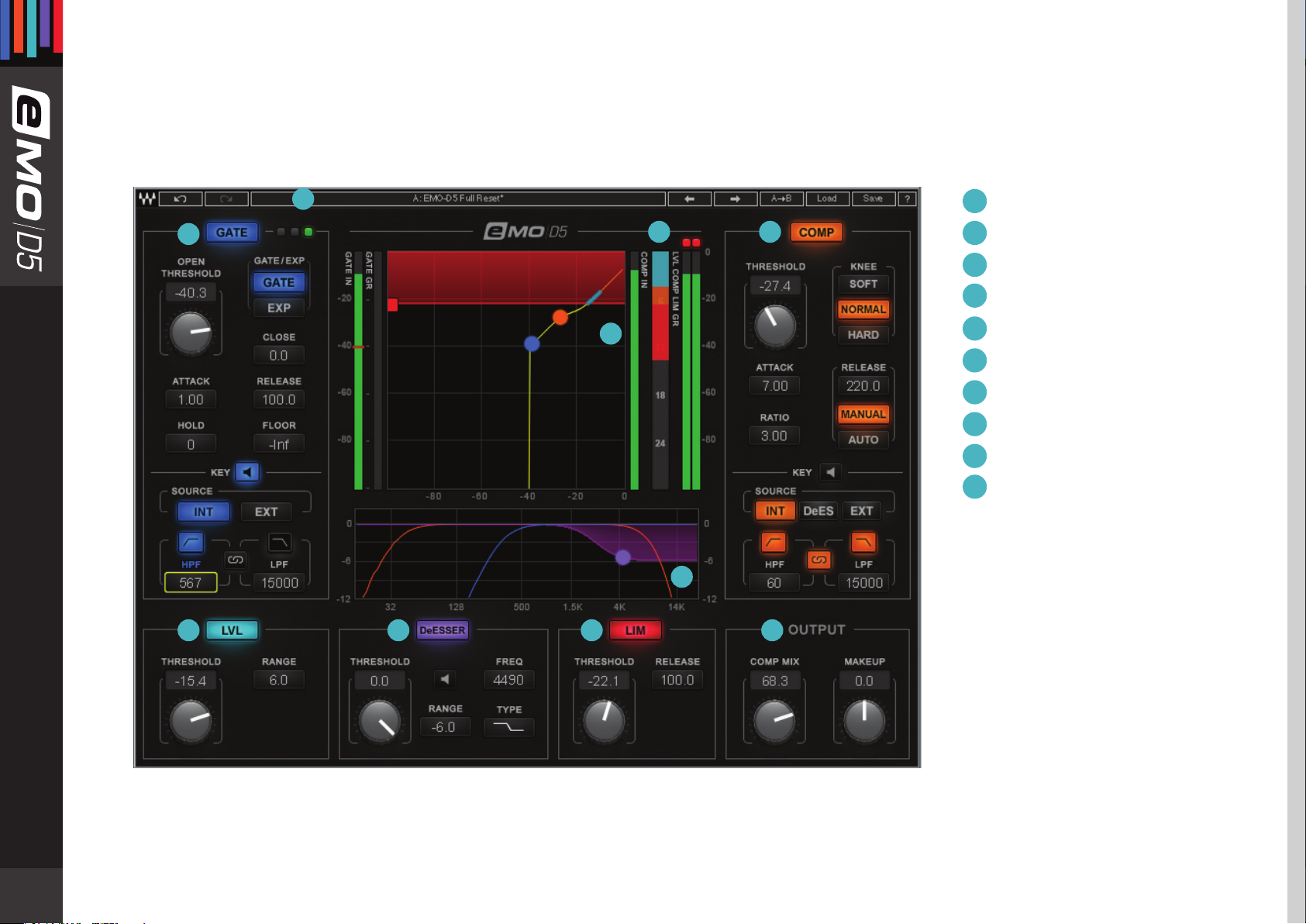
3 .1 I n t e r f a c e
1
2
10
9
3
1
WaveSystem Toolbar
Gate
2
3
Compressor
4
Leveler
DeEsser
5
Limiter
6
Output
7
8
Filter Graph
9
Input/Output Graph
10
Combined Gain
Reduction Meter
8
4
5
6
7
6
Page 7
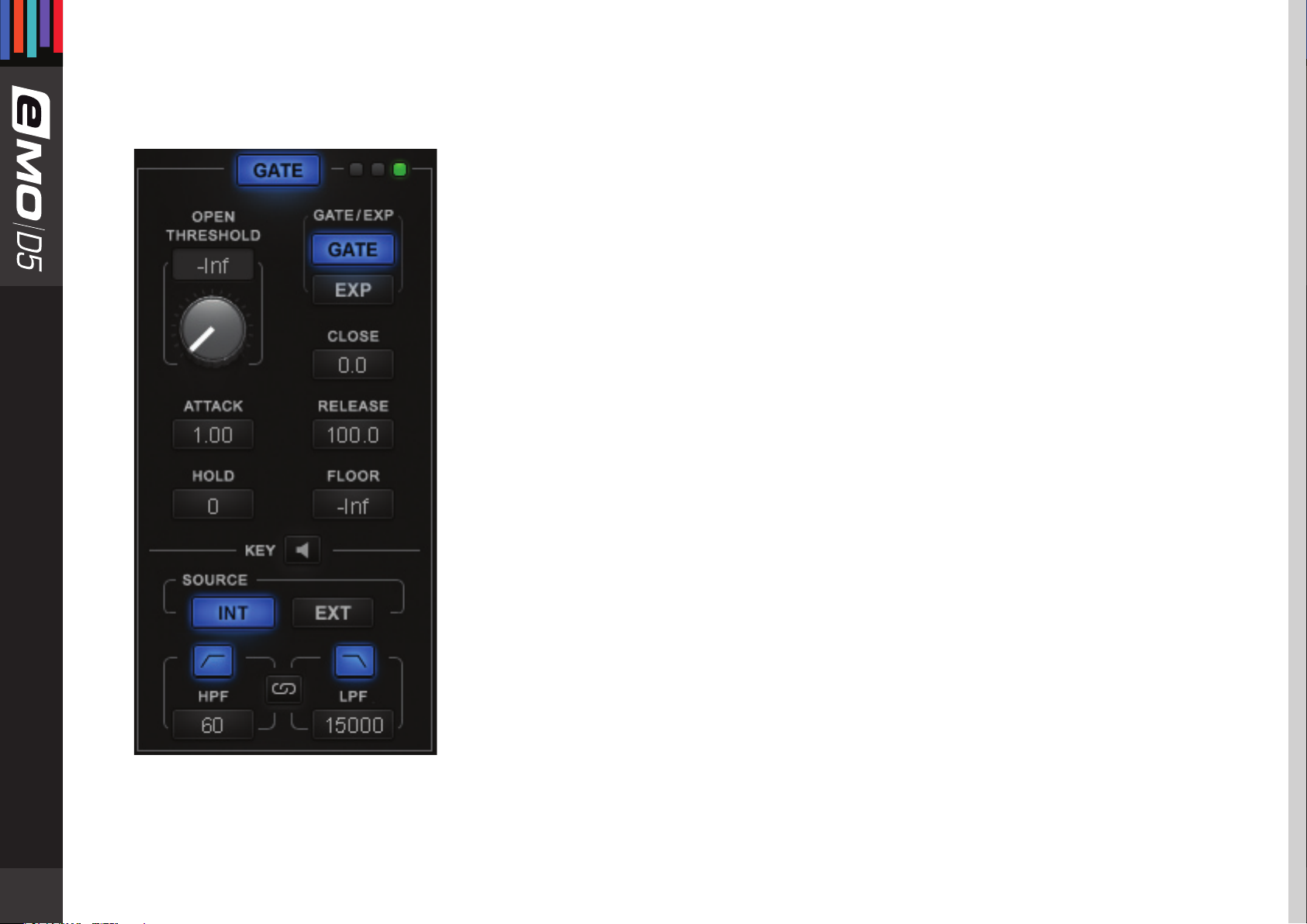
3.2 Gate Section
Controls
GATE: Turns on or bypasses the Gate section.
Range: On, O
Default: O
GATE/EXP: Toggles between Gate and Expander modes.
Gate mode provides sharper results, basically muting all
audio below the Threshold level.
Expander mode provides more natural results, never muting the audio. The Gate is never
completely closed, providing “softer” gating.
Additional Gate controls allow natural results even in Gate mode.
Range: GATE, EXP
Default: GATE
OPEN THRESHOLD: Sets the Gate Open level.
Range: -Inf to 0 db
7
Default: -Inf
CLOSE: Allows independent adjustment for the Gate Close level.
Range: -48 to 0 db
Default: 0 db
FLOOR: Adjusts the level of maximum gain reduction.
Range: -Inf to 0 db
Default: -Inf
ATTACK: Determines how quickly the Gate opens.
Range: 0.1 to 100 ms
Default: 1 ms
Page 8
HOLD: Sets how long the Gate will stay open even if the signal falls below Threshold.
Range: 0 to 10000 ms
Default: 0 ms
RELEASE: Sets how fast the Gate closes (fades out) after the signal falls below Threshold.
Range: 1 to 1000 ms
Default: 100 ms
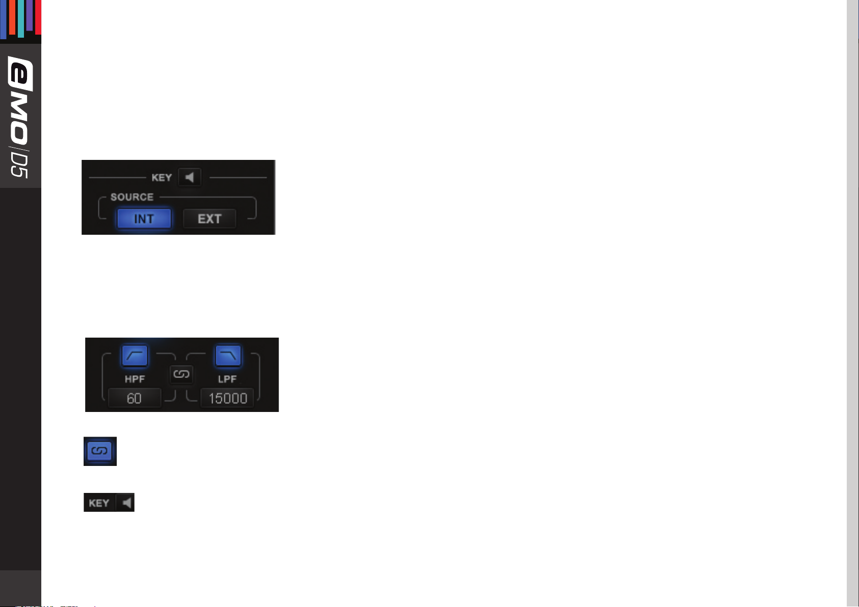
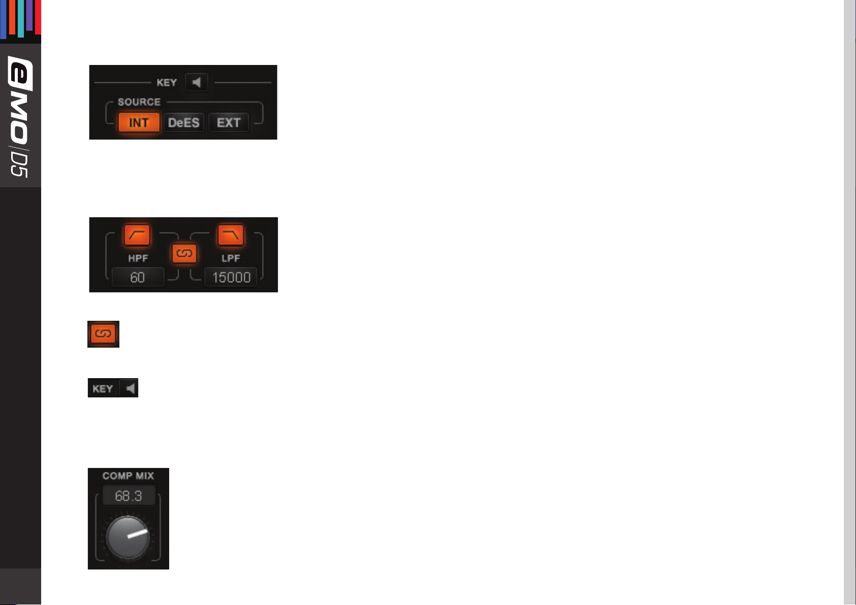
KEY: Lets you choose, lter and audition the sidechain source.
The Key feature adds additional precision in controlling dynamics.
The Key acts as a trigger that activates the dynamic process.
It can be Internal (INT) – triggered by its own signal, or External (EXT) – triggered by another
audio channel through sidechain routing, in which case the external signal is routed
independently as a sidechain input to the Gate.
Range: INT, EXT
Default: INT
In addition, the Key signal (whether INT or EXT) can be ltered using HP/LP lters.
HPF Range: 16 to 18000 Hz
8
Default: 60 Hz
LPF Range: 16 to 18000 Hz
Default: 15000 Hz
To link HPF and LPF, hit the Filter Link
Filter Link Range: On, O
Default: O
To audition Key signals, hit the Preview. The auditioned audio will be aected by Filters state, but unaected dynamically.
Range: On, O
Default: O
Page 9

Meters and Indicators
Gate state LEDs
Green = Open, Yellow = Hold, Red = Close
GATE IN meter
Shows input level. When Key is in EXT, the meter will show the input level of the external sidechain. A single red marker on the Gate
In meter indicates the Gate Threshold and Close levels. You can set the Gate Close level independently of Gate Threshold, in which
case the Close marker will stay red, while the Threshold marker will become green.
GATE GR Meter
Shows the amount of attenuation introduced by the Gate section.
This attenuation is not reected in the Combined Gain Reduction Meter.
9
Page 10
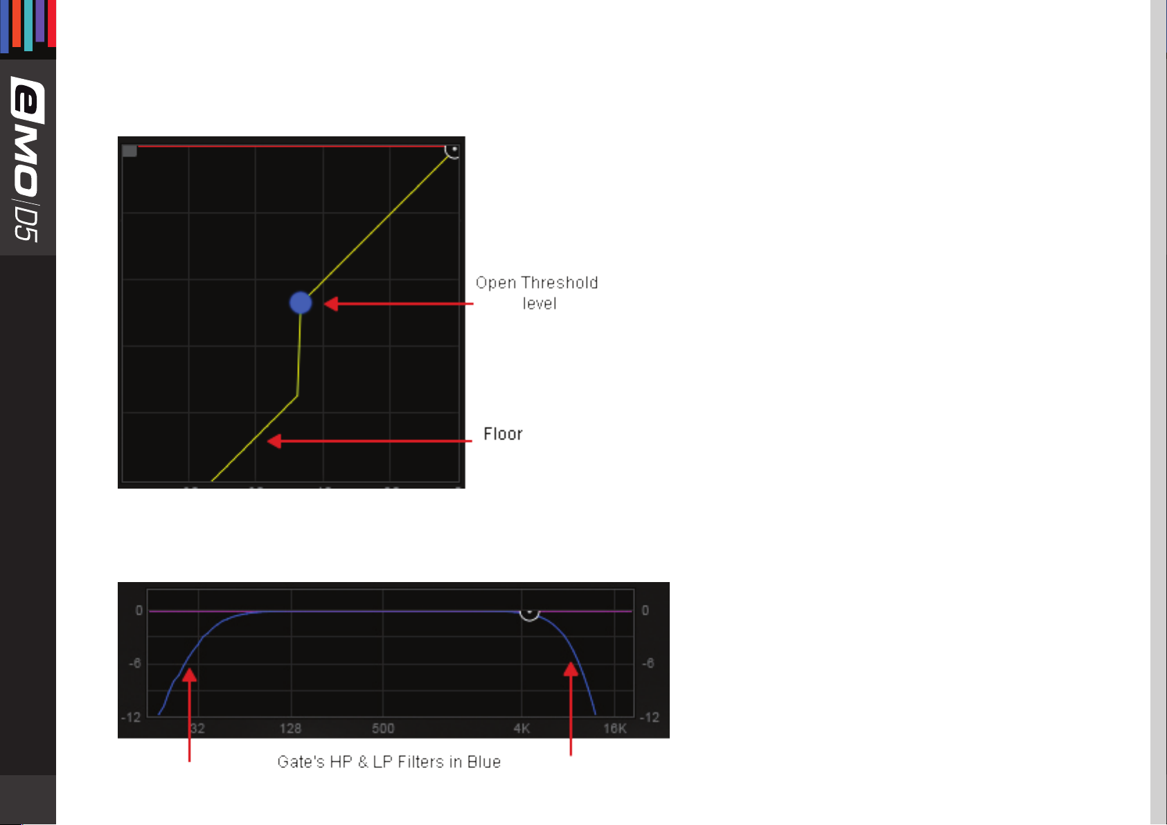
Input/Output Graph
Indicates Gates Range and Open Threshold levels.
The Open Threshold level can be adjusted by dragging the blue dot.
10
Gate Key Filters: shown in the Filter Graph as blue curves.
Page 11

3.3 Compressor Section
Controls
COMP: Turns on or bypasses the Compressor section.
Range: On, O
Default: O
KNEE: Sets how aggressively the Compressor reacts to the signal.
Range: SOFT, NORMAL, HARD
Default: NORMAL
THRESHOLD: Sets the Compressor’s engagement level.
Range: -48 to 0 db
Default: 0 db
RATIO: Determines how hard the signal is compressed.
Range: 1 to 20
Default: 3
ATTACK: Determines how quickly the Compressor reacts to a signal.
11
Range: 0.5 to 300 ms
Default: 7 ms
RELEASE: Determines how fast the Compressor reduces processing after the signal falls
below the Threshold. When in Manual mode, the release time is set by the Release Value.
When in Auto mode, the release time adjusts automatically within the range set by the
Release Value.
Release modes: AUTO, MANUAL
Default: MANUAL
Release time range: 1 to 3000 ms
Default: 220 ms
Page 12
KEY: Lets you choose, lter and preview DeEsser and Compressor routing or external sidechain source.
The Key feature adds additional precision in controlling dynamics. The Key acts as a trigger that
activates the dynamic process. The Key can be internal – triggered by its own signal, or External
– triggered by another audio channel through sidechain routing to the Compressor.
The Compressor has two internal routing options:
• INT: Compressor triggered by its own signal; DeEsser routed post-Compressor
• DeES: DeEsser routed pre-Compressor
Range: INT, DeES, EXT
Default: INT
In addition, the Key signal (whether internal or external) can be ltered using HP/LP lters.
HPF Range: 16 to 18000 Hz
Default: 60 Hz
LPF Range: 16 to 18000 Hz
Default: 15000 Hz
To link HPF and LPF, hit the Filter Link.
Filter Link Range: On, O
12
Default: O
To audition the Key signals, hit the Preview. The auditioned audio will be aected by Filters state, but unaected
dynamically.
Range: On, O
Default: O
COMP MIX (located in the OUTPUT section): Allows parallel compression by mixing the compressed and the
uncompressed audio.
Range: 0 (= uncompressed audio) to 100 (= compressed audio)
Default: 100
Page 13

Meters and Indicators
COMP IN Meter:
Shows the input level. When Key is in EXT, the meter will show the input level of the External Key.
LVL COMP LIM GR Meter:
Combined gain reduction meter for the Leveler, Compressor and Limiter. The amount of gain reduction introduced by the
Compressor is shown in orange.
Input/Output Graph:
Indicates the Compressor’s Threshold level, Knee and Ratio. Threshold level can be adjusted by dragging the orange dot.
13
Page 14

Filter Graph:
Shows the Compressor's Key lters in orange.
14
Page 15

3.4 Leveler Section
A leveler is used to maintain constant levels over long segments of audio. Essentially, a leveler is a compressor set to very long attack
and release times. A leveler can also be viewed as an RMS compressor. The leveler smoothly and transparently gain-rides any signal
that exceeds its threshold, bringing it back down as close as possible to the desired target level (the threshold).
Controls
LVL: Turns on or bypasses the Leveler section.
Range: On, O
Default: O
THRESHOLD: Sets both the threshold above which leveling is applied and the target to
which the audio
signal is leveled.
Range: -48 to 0 db
Default: 0 db
RANGE: Sets the range of the Leveler’s processing.
15
Range: 0 to 48 db
Default: 6 db
Page 16

Meters and Indicators
Input/Output Graph:
Shows the Leveler’s range
and threshold/target levels. Leveler shown as a light
blue line.
LVL COMP LIM GR Meter:
Combined gain reduction
meter for the Leveler, the Compressor and the Limiter.
The amount of gain reduction introduced by the Leveler is shown in light blue.
16
Page 17

3.5 DeEsser Section
Controls
DeESSER: Turns on or bypasses the
DeEsser section.
Range: On, O
Default: O
THRESHOLD: Sets the DeEsser’s engagement level.
The DeEsser’s threshold uses adaptive sensing to provide more natural results.
Range: -48 to 0 db
Default: 0 db
17
TYPE: Sets the band type – high-pass or band-pass lter.
Range: Shelf Bell Notch
Default: Shelf
FREQ: Sets the roll-o start point for a high-pass lter or the center frequency for the band-pass lter.
Range: 16 to 21357 Hz
Default: 4490 Hz
RANGE: Sets the amplitude of the DeEsser’s processing.
Range: -12 to 0 db
Default: -6 db
PREVIEW: Lets you audition the DeEsser’s lter.
Range: On, O
Default: O
Page 18

Meters and Indicators
Filter Graph:
Shows the DeEsser’s type, frequency, range and DS gain reduction in purple.
Frequency and range can be adjusted by dragging the purple dot.
Note: The DeEsser’s attenuation is not reected in the Combined Gain Reduction Meter.
18
Page 19

3.6 Limiter Section
Controls
Meters and Indicators
LIM: Turns on or bypasses the Limiter section.
Range: On, O
Default: O
THRESHOLD: Sets engage level for Limiter.
Range: -48 to 0 db
Default: 0 db
RELEASE: Sets how fast the Limiter reduces the processing after the signal falls below the
Threshold. This function utilizes adaptive technology, which means that release time adjusts
automatically to the Release range value.
Range: 0.1 to 1000 ms
Default: 100 ms
19
Input/Output Graph:
Shows the Limiter’s Threshold level.
Limiter shown as a horizontal red line.
LVL COMP LIM GR Meter:
The Limiter’s gain reduction meter.
Shows the amount of attenuation
introduced
by the Limiter in red.
Page 20

3.7 Other Meters and Controls
Makeup Gain
The Makeup Gain control is used to compensate for the gain reduction introduced by the multiple dynamic tools.
Make sure you don't clip the Output meter when boosting Makeup Gain.
Range: -18 to 18 db
Default: 0 db
Combined Gain Reduction Meter
The Combined Gain Reduction
Meter shows in one unied view
the gain reduction introduced by
the Leveler, the Compressor,
and the Limiter.
This meter does not reect the
gain reduction introduced by the
DeEsser and the Gate.
Output Meter
The Output meter shows the nal
output level produced by eMo-D5
You see a single meter for the Mono
component, two meters (Left and
Right) for the Stereo component.
The Output meter features the Peak
Led as well.
20
Page 21

3.8 eMo-D5 Block Diagram
21
Page 22

Chapter 4: the Wavesystem
4.1 The WaveSystem Toolbar
All Waves plugins feature the WaveSystem toolbar which takes care of most administrative functions you will encounter while
working with your Waves software. The features of the WaveSystem toolbar are the same on practically all Waves plugins, so
familiarity with its features will be helpful whichever plugin you are using.
Toolbar Functions
Opens the plugin About box
Undo Undoes the last 32 actions
Redo Redoes the last 32 undone actions
Setup A/B Toggles between two presets, useful for comparison of parameter settings
L/R
Arrows
Copy A
> B
Load Recalls presets from le
Save Saves presets in the Waves le formats
? Opens the PDF manual for the plugin you are using
Move to the previous or next preset
Copies the current settings to the second preset register
4.2 Preset Handling
Preset Types
Factory Presets are permanent presets in the Load menu. Factory presets cannot be overwritten or deleted. When applicable,
dierent component plugins may have dierent factory presets.
User Presets are your favorite settings of the plugin saved as a preset in the Load menu, under ‘User Presets’. User Presets can be
overwritten and deleted.
22
Page 23

Setup Files may contain more than one preset. For example, a single le can contain all the presets for a session. When you open
a Setup File, all its setups become part of your Load pop-up menu for fast access. This can be particularly useful with multiple
instances of a plugin in a single session. By saving all the settings you create into a single Setup File, they can all be quickly available
for every instance of that plugin.
Loading Presets and Setups
Click on the Load button to see the Load pop-up menu. The menu is divided into four sections. If a section is not
currently available it will not appear in the Load pop-up menu.
Open Preset File… Select to open any setup or preset le, whether from the Library or your own creations.
‘Filename.xps’: Displays any currently loaded Setup File and its presets.
Factory Presets: Displays the default Factory Presets.
User Presets: Displays any loaded User Presets.
Saving Presets and Setups
Click on the Save button to see the Save pop-up menu. Four options are available. If an option is not currently available
it will be grayed out and inaccessible
23
Save to New File… Select this to start a new Setup le. There are two prompts - rst for the setup lename, then for the
preset name. You must provide a name for both the setup le and the preset. Click OK (ENTER) to
complete the save. It is a good idea to create a folder in which to save several setup les for a project.
Save ‘File Name’ –
“Preset Name”
Overwrites the settings of the loaded preset (whether a User Preset or a preset from a Setup File)
with the current settings. If a Setup File is currently loaded, the name of the Setup File is displayed
followed by the name of the preset itself. If a User Preset is loaded, its name is displayed.
Save to ‘File Name’ As… Saves the current settings as a new preset into the Setup le that is open (if one is not open, the
option is grayed out). You will be prompted to give the preset a name.
Put into Preset Menu As… Save the current settings into a User Preset that will always be in your Load menu (until deleted). You
will be prompted to give this preset a name. User Presets are stored in the plugin’s preference le.
Page 24

Deleting Presets
You may delete User Presets and presets within a Setup File. Factory Presets and Setup Library les cannot be deleted or overwritten.
1. Hold the Command (Mac)/Control (PC) key down.
2. Click-and-hold the Load button to see the pop-up menu.
3. While still holding the Command/Control key, select the preset or setup to delete.
4. A conrmation box will appear, allowing you to cancel or ‘OK’ the deletion.
A/B Comparison and Copying
The Setup A/Setup B button may be clicked to compare two settings. If you load a preset in the Setup B position, this
will not aect the preset loaded into the Setup A position, and vice-versa.
If you want to slightly modify the settings in Setup A, copy them to Setup B by clicking the Copy to B button, then alter Setup A and
compare with the original Setup B.
The name of the current setup will be shown in the title bar (on platforms which support it), and will switch as you change from
Setup A to Setup B.
Note: an asterisk will be added to the preset name when a change is made to the preset.
24
Page 25

4.3 Interface Controls
Controls can be in one of three states:
1. Not Selected where the control is not the target of any user entry
2. Selected where the control is the target of mouse control entry only
3. Selected and Active where the control is the target for both mouse and keyboard entry
Toggle Buttons
Toggle buttons display the state of a control, and allow switching between two or more states. Single-click to change the control’s
state. Some toggle buttons have a text display which updates with the current setting, and others (bypass, solo, or monitoring
toggles) illuminate when the control is active.
Some plugins have link buttons between a pair of toggle buttons, allowing click-and-drag adjustment while retaining the oset
between the controls.
Value Window Buttons
Value windows display the value of a control and allow click-and-drag adjustment, or direct control via the keyboard.
• Using the mouse, click-and-drag on the value window to adjust. Some value windows support left/right, some up/down (as you
hover over a button, arrows will appear to let you know which direction of movement that button supports). You may also use
25
your mouse-wheel to adjust parameter values.
• Using the arrow keys, click once with mouse to select the button, and then use up/down – left/right (depending on the direction
supported by that button) to move in the smallest incremental steps across the button’s range (holding down the arrow keys will
move faster through the range).
• Using key entry, double click on the button to open the value window, and directly enter the value from your keyboard. If you
enter an out of range number, the button stays selected but remains at the current setting. (System beeps if system sounds are on.)
Some plugins have link buttons between a pair of value windows, allowing click-and-drag adjustment while retaining the oset
between the controls.
Page 26

Hover Box
Hovering boxes will appear and display the control value when hovering with the mouse over the control.
Multiple Control Selection
One of the most powerful features of the WaveSystem is the ability to select and adjust multiple controls simultaneously. Using the
mouse, drag-select the desired group of buttons or graphic controls by clicking and holding at a point outside the controls, and
forming a rectangle that includes the controls you wish to adjust. Alternatively, press and hold Shift while clicking the mouse on any
control you wish to link. This method is useful when you want to select two or more controls that are not adjacent to one another.
TAB Functions
TAB moves the ‘selected’ status to the next control, with shift-TAB moving in the reverse direction. Additionally, the Mac has an
option-TAB function for ‘down’ movement and shift-option-TAB for ‘up’ movement where applicable.
If you have several Value Window Buttons selected, TAB functions will take you through the selected controls only. Hitting Esc or
Return will return the ‘focus’ to the DAW application.
4.4 Waves Preferences (Pro Tools only)
When launching Pro Tools, hold Shift to view the Waves plugin Preferences window. The following options are available:
• Don’t use AudioSuite plugins
26
• Don’t use RTAS plugins
• Rescan all plugins
• HUI control surface support (low resolution)
• Enable single-click text entry
 Loading...