

Page 1

Instructions for Installing TD-300
Elevator Channel Drain
!
WARNING
Read this Manual BEFORE using this equipment.
Failure to read and follow all safety and use information
can result in death, serious personal injury, property
damage, or damage to the equipment.
Keep this Manual for future reference.
!
WARNING
Local building or plumbing codes may require modifications to the information provided. You are required to
consult the local building and plumbing codes prior
to installation. If the information provided here is not
consistent with local building or plumbing codes, the
local codes should be followed. This product must be
installed by a licensed contractor in accordance with
local codes and ordinances.
IS-WD-TD-300-CAN
NOTICE
Follow the guidelines listed here for proper installation,
operation, and maintenance.
Installation Guidelines
General Note: Please consult all local plumbing codes before installing
Watts channel drains.
Introduction
Watts TD-300 Elevator Channel Drain is designed with safety and aesthetics in
mind. Our channel drain is engineered to withstand heavy foot traffic, as well as
heavy loads without compromising style and design. The stainless steel surface area
provides durability and safe integration in outdoor to indoor transitions and in elevator
and building thresholds. The TD-300 is heel proof, wheelchair accessible and ADA
compliant. It complies with 2013 California Building Code 403.6.1, 403.6.2, 3007.4,
3008.4, and SFFC Section 511.1.4 for a flow rate of 100 GPM.
Benefits Of Elevator & Threshold Drains
Low profile offers a smooth integration between outdoor and indoor areas
Available in lengths from 36" min. to 96" max.
12 ga. 304 stainless steel is engineered for both durability and style
Removable grating allows for low maintenance and easy installation
TD-300 offers superior flow rates while maintaining a shallow depth
Page 2
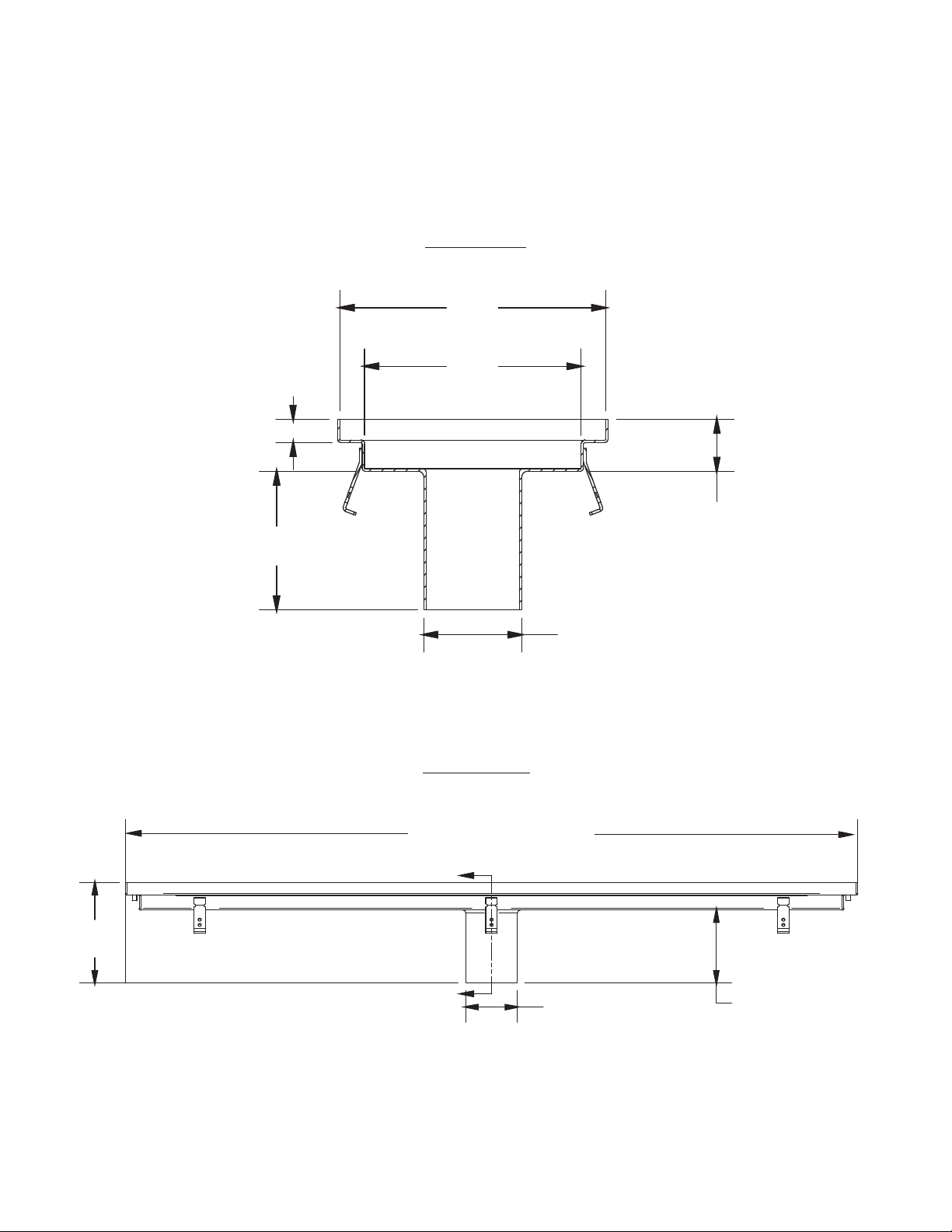
Note: The TD-300 offers a 6"(152) no hub outlet. The product ships standard with center
outlet. End outlets are available by special request. Please make sure that you have specified
the correct area before installation begins.
Note: Minimum dimensional requirements must be met to satisfy 100 gpm flow rate
specification.
End View
11 1/2"
(292)
(25)
6"
(152)
1"
9 3/8"
(238)
2 1/4"
(57)
4 1/4"
(108)
Side View
8 1/4"
(210)
2
Specify (36" Min. / 96" Max.)
A
A
4 1/4"
(108)
6"
(152)
Page 3

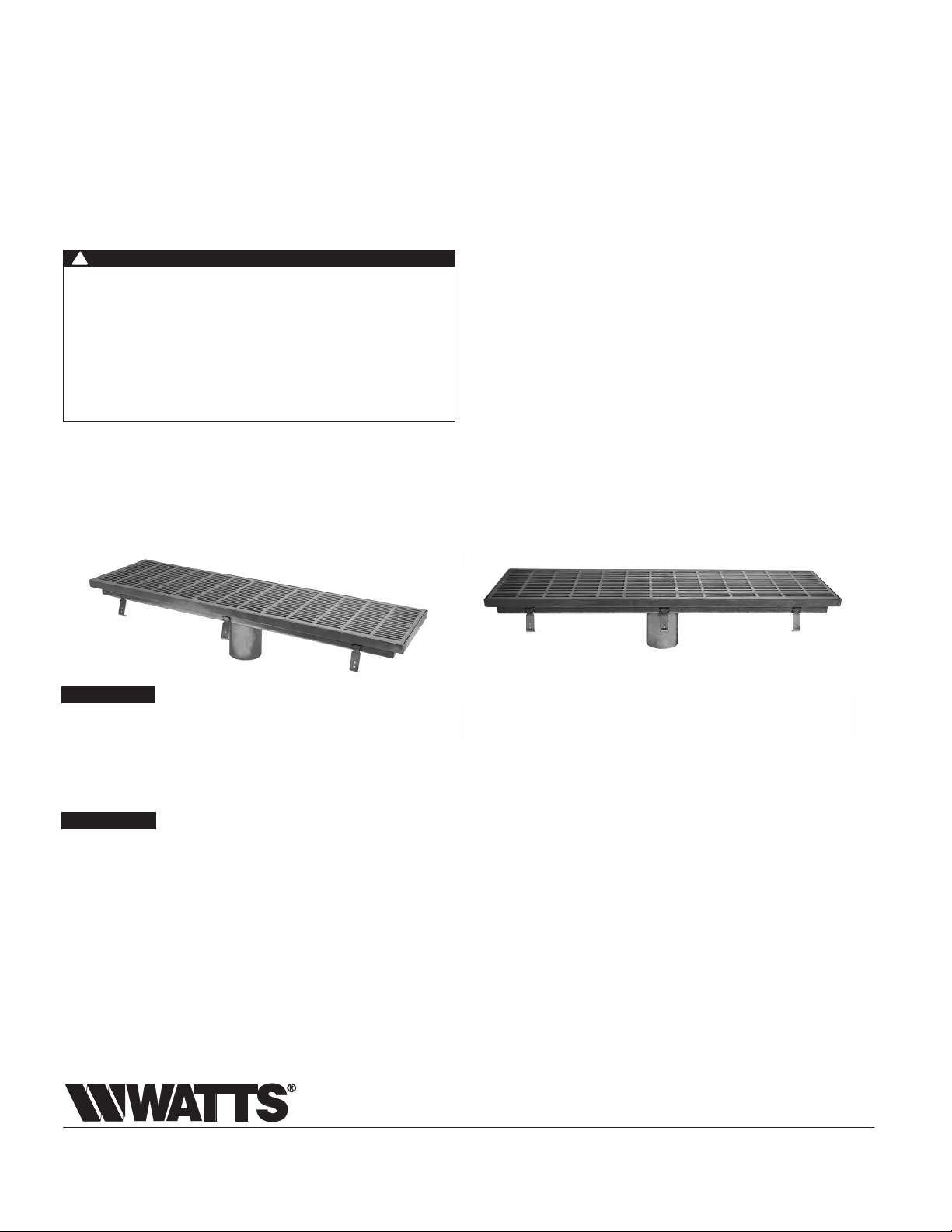
Anchor Strap
Top View
Watts TD-300 installs during new construction or in existing floors
Elevator/Threshold channels should sit slightly below flooring to ensure a smooth
transition from one area to another when the grate is installed. The grate should
match up flush with the floors and create a safe level transition.
Installing the channel
Leader drain pipes must be installed to connect with the center or end drain outlet
in order to divert and filter excess water.
Leader drain pipes are used to connect the drain to the intended drain lines. These
pipes should be in place and designed to connect to the drain outlet whether it is
located in the center or in the ends of the channel.
The drain is designed to fit into "boxed-out" areas in both new construction and in
existing floors.
Wood is used to create a form or boxed-out area to hold the channel.
Create a solid level base for the channel. This may be done with concrete or other
materials. Use a level to ensure that the channel is level and will properly meet
floor level when grate is installed.
Form the approach to the entrance by laying the required sub-base up to the
channel, leaving sufficient space for the surface finish. Any final adjustments
should be made at this time.
Anchor straps may be screwed into existing concrete or flooring, or screwed into
wood forms to hold the channel steady during a concrete pour.
Concrete may be poured around the channel.
3
Page 4
Installing the grate
The TD-300 is equipped with type 304 stainless steel grating. The stainless steel is
both durable and allows for an aesthetically attractive entrance.
The grate is rated for Class A top load classification and complies with both ADA
and heel-proof requirements.
Lower the grate onto the top of the channel and lock down to the channel with
two vandal-proof flathead machine screws, one on each end.
!
WARNING
Need for Periodic Inspection/Maintenance: This product
must be tested periodically in compliance with local codes,
but at least once per year or more as service conditions
warrant. All products must be retested once maintenance
has been performed. Corrosive water conditions and/or
unauthorized adjustments or repair could render the product
ineffective for the service intended. Regular checking and
cleaning of the product’s internal and external components
helps assure maximum life and proper product function.
Maintenance
The stainless steel grating offers easy-to-remove grating that provides accessible
cleaning and maintenance. The grating can be removed by removing both screws
and lifting the grate out for cleaning the channel of debris.
NOTICE
The information contained herein is not intended to replace the
full product installation and safety information available or the
experience of a trained product installer. You are required to
thoroughly read all installation instructions and product safety
information before beginning the installation of this product.
NOTICE
Inquire with governing authorities for local installation
requirements
Limited Warranty: Watts Regulator Co. (the “Company”) warrants each product to be free from defects in material and workmanship under normal usage for a period of one year from the date of
original shipment. In the event of such defects within the warranty period, the Company will, at its option, replace or recondition the product without charge.
THE WARRANTY SET FORTH HEREIN IS GIVEN EXPRESSLY AND IS THE ONLY WARRANTY GIVEN BY THE COMPANY WITH RESPECT TO THE PRODUCT. THE COMPANY MAKES NO OTHER
WARRANTIES, EXPRESS OR IMPLIED. THE COMPANY HEREBY SPECIFICALLY DISCLAIMS ALL OTHER WARRANTIES, EXPRESS OR IMPLIED, INCLUDING BUT NOT LIMITED TO THE IMPLIED
WARRANTIES OF MERCHANTABILITY AND FITNESS FOR A PARTICULAR PURPOSE.
The remedy described in the first paragraph of this warranty shall constitute the sole and exclusive remedy for breach of warranty, and the Company shall not be responsible for any incidental, special
or consequential damages, including without limitation, lost profits or the cost of repairing or replacing other property which is damaged if this product does not work properly, other costs resulting
from labor charges, delays, vandalism, negligence, fouling caused by foreign material, damage from adverse water conditions, chemical, or any other circumstances over which the Company has no
control. This warranty shall be invalidated by any abuse, misuse, misapplication, improper installation or improper maintenance or alteration of the product.
Some States do not allow limitations on how long an implied warranty lasts, and some States do not allow the exclusion or limitation of incidental or consequential damages. Therefore the above
limitations may not apply to you. This Limited Warranty gives you specific legal rights, and you may have other rights that vary from State to State. You should consult applicable state laws to
determine your rights. SO FAR AS IS CONSISTENT WITH APPLICABLE STATE LAW, ANY IMPLIED WARRANTIES THAT MAY NOT BE DISCLAIMED, INCLUDING THE IMPLIED WARRANTIES OF
MERCHANTABILITY AND FITNESS FOR A PARTICULAR PURPOSE, ARE LIMITED IN DURATION TO ONE YEAR FROM THE DATE OF ORIGINAL SHIPMENT.
USA: Tel: (800) 338-2581 • Fax: (828) 248-3929 • Watts.com
Canada: Tel: (905) 332-4090 • Fax: (905) 332-7068 • Watts.ca
Latin America: Tel: (52) 81-1001-8600 • Watts.com
IS-WD-TD-300-CAN 1916 EDP# 1915422 © 2019 Watts
Page 5

IS-WD-TD-300-CAN
Instructions pour l’installation de TD-300
Drain de canalisation pour ascenseur
!
AVERTISSEMENT
Lisez ce manuel AVANT d’utiliser cet équipement.
Le non-respect de toutes les instructions de sécurité
et d’utilisation de ce produit peut endommager ce
LA SÉCURITÉ
AVANT
TOUT
!
AVERTISSEMENT
Les codes locaux du bâtiment ou de la plomberie peuvent
nécessiter des modifications aux renseignements
donnés. Vous êtes tenus de consulter des codes locaux
du bâtiment ou de la plomberie avant de commencer
l’installation. Si les renseignements donnés ci-dessous ne
sont pas cohérents avec les codes locaux du bâtiment ou
de la plomberie, les codes locaux doivent être respectés.
Ce produit doit être installé par un entrepreneur licencié
conformément aux codes et règlements locaux.
produit ou entraîner d’autres dommages matériels, des
blessures graves ou la mort.
Conservez ce manuel pour référence ultérieure.
AVIS
Suivez les consignes ci-dessous pour une installation, une
utilisation et une maintenance adéquates.
Directives d’installation
Remarque générale: veuillez consulter tous les codes locaux de plomberie
avant l’installation des drains de canalisation de Watts.
Introduction
Le drain de canalisation pour ascenseur TD-300 est conçu avec la sécurité et l’esthétique à
l’esprit. Notre drain de canalisation est spécialement conçu pour résister à une forte circulation
piétonnière, ainsi que des charges lourdes, sans compromettre le style et la conception. La
surface en acier inoxydable procure la durabilité et l’intégration sécuritaire des transitions de
l’extérieur à l’intérieur, et dans les seuils d’ascenseur et de bâtiment. Le TD-300 est résistant
aux talons, accessible pour les fauteuils roulants et conforme à l’ADA. Il respecte le California
Building Code de2013 403.6.1, 403.6.2, 3007.4, 3008.4, et la section511.1.4 du SFFC pour
le débit de 100gallons par minute (378L par minute).
Avantages des drains d’ascenseur et de seuil
Le profil bas offre une intégration lisse entre les zones extérieures et intérieures.
Offert en longueurs de 36po min./96po max. (914mmmin./2438mmmax.).
L’acier inoxydable304 de calibre12 est spécialement conçu pour la durabilité et le style.
Le retrait des grilles permet un faible entretien et une installation facile.
TD-300 offre des débits supérieurs, tout en conservant une faible profondeur.
Page 6

Remarque: le TD-300 offre une sortie de 6po (152mm) sans moyeu. Le produit est expédié
standard avec une sortie centrale. Les sorties d’extrémité sont disponibles par demande
spéciale. Assurez-vous d’avoir précisé la zone appropriée avant de préparer l’installation.
Remarque: les exigences minimales de dimensions doivent être respectées pour répondre à
un débit de 100gallons par minute (378L par minute) qui est précisé.
Vue de l’extrémité
11 1/2 po
(292 mm)
1 po
(25 mm)
6 po
(152 mm)
9 3/8"po
(238 mm)
2 1/4 po
(57 mm)
4 1/4 po
(108 mm)
Vue de côté
8 1/4 po
(210 mm)
2
Préciser (36 po min./96 po max. [914 mm min./2 438 mm max.])
A
A
4 1/4 po
(108 mm)
6 po
(152 mm)
Page 7

Sangle d’ancrage
Anchor Strap
Vue de dessus
Top View
Le TD-300 de Watts s’installe lors d’une nouvelle construction ou dans des
planchers existants
Les canalisations d’ascenseur/de seuil devraient être placées légèrement sous le couvre
plancher afin d’assurer une transition lisse d’une zone à l’autre lorsque la grille est
installée. La grille devrait être au ras avec les planchers et créer une transition sécuritaire
des niveaux.
Installation de la canalisation
Les tuyaux principaux des drains devraient être installés pour raccorder avec la sortie du
centre ou de l’extrémité, afin de détourner et filtrer l’excès d’eau.
Les tuyaux principaux des drains sont utilisés pour raccorder le drain aux tuyaux prévus
de drainage. Ces tuyaux devraient être en place et conçu pour se raccorder à la sortie du
drain, qu’elle soit située au centre ou à l’extrémité de la canalisation.
Le drain est conçu pour être logé dans des zones «encastrées», dans les constructions
neuves et les planchers existants.
Le bois est utilisé pour créer une forme ou une zone encastrée pour tenir la canalisation.
Créer une base de niveau solide pour la canalisation. Cela peut se faire en béton ou
d’autres matériaux. Utiliser un niveau afin d’assurer que la canalisation est de niveau et
arrivera de façon appropriée au niveau du plancher lorsque la grille est installée.
Former l’approche à l’entrée en posant la sous-base nécessaire jusqu’à la canalisation,
laissant suffisamment de place pour la finition de la surface. Tout ajustement final devrait
être effectué à ce moment.
Des sangles d’ancrage peuvent être vissées dans le béton ou le couvre-plancher existant,
ou vissées dans des formes en bois pour tenir la canalisation en place lorsque le béton
est coulé.
Le béton peut être coulé autour de la canalisation.
3
Page 8

Installation de la grille
Le TD-300 est muni d’une grille en acier inoxydable de type304. L’acier inoxydable
est à la fois durable et permet une entrée d’allure esthétique.
La grille est cotée pour une classification de charge supérieure de classeA et
respecte les exigences de l’ADA et de résistance aux talons.
Abaisser la grille sur le dessus de la canalisation et la fixer à la canalisation à l’aide
des deux vis mécaniques à tête plate à l’épreuve du vandalisme.
!
AVERTISSEMENT
Nécessité d'inspection périodique/maintenance : Ce produit
doit être testé périodiquement en conformité avec les codes locaux,
mais au moins une fois par an ou plus, comme les conditions de
service le justifient. Tous les produits doivent être testés une fois
que les opérations d'entretien ont été effectuées. Des conditions
d'admission corrosives et/ou des réglages ou des réparations
non autorisés peuvent rendre le produit inefficace pour le service
prévu. La vérification et le nettoyage réguliers des composants
internes et externes du produit contribuent à assurer une durée de
vie maximale et un fonctionnement correct du produit.
Entretien
La grille en acier inoxydable est une grille facile à retirer qui offre l’accessibilité pour
le nettoyage et l’entretien. La grille peut être retirée en retirant les deux vis, pour
ensuite la lever et nettoyer tout débris de la canalisation.
AVIS
Les présentes informations ne sont pas destinées à remplacer
les informations d’installation et de sécurité complètes du produit
ou l’expérience d’un installateur professionnel. Vous êtes tenu de
lire attentivement toutes les instructions d’installation et toutes
les informations de sécurité du produit avant de commencer
l’installation de ce produit.
AVIS
Renseignez-vous auprès des autorités de réglementation pour
les exigences d’installation locales.
Garantie limitée: Watts Regulator Co. (la «Société») garantit que chacun de ses produits est exempt de vice de matériau et de fabrication dans des conditions normales d’utilisation pour une période
d’un an à compter de la date d’expédition d’origine. Si une telle défaillance devait se produire au cours de la période sous garantie, la Société aura à sa discrétion l’alternative suivante: le remplacement
ou bien la remise en état du produit, sans frais pour le demandeur.
LA PRÉSENTE GARANTIE EXPRESSE EST LA SEULE ET UNIQUE GARANTIE, RELATIVE AU PRODUIT, FOURNIE PAR LA SOCIÉTÉ. LA SOCIÉTÉ NE FORMULE AUCUNE AUTRE GARANTIE, EXPRESSE
OU IMPLICITE. LA SOCIÉTÉ REJETTE AUSSI FORMELLEMENT PAR LA PRÉSENTE TOUTE AUTRE GARANTIE, EXPRESSE OU IMPLICITE, Y COMPRIS (SANS S’Y LIMITER) LES GARANTIES
IMPLICITES DE QUALITÉ MARCHANDE ET D’APTITUDE À UN USAGE PARTICULIER.
Le dédommagement précisé dans le premier paragraphe de cette garantie constitue la seule et unique alternative en cas de service demandé sous cette garantie. La Société ne pourra être tenue
responsable de dommages spéciaux ou indirects, incluant, sans s’y limiter: pertes de profit, coûts de réparation ou de remplacement des autres biens ayant été endommagés si ce produit ne fonctionne
pas correctement, autres coûts afférents aux frais de main-d’œuvre, de retards, de vandalisme, de négligence, d’engorgement causés par des corps étrangers, dommages causés par des propriétés
de l’eau défavorables, des produits chimiques, ou toute autre circonstance indépendante de la volonté de la Société. La présente garantie est déclarée nulle et non avenue en cas d’usage abusif ou
incorrect, d’application, d’installation ou d’entretien incorrects ou de modification du produit.
Certains États n’autorisent pas les limitations de durée d’une garantie tacite ou l’exclusion ou la limitation des dommages accessoires ou indirects. En conséquence, ces limitations pourraient ne pas
s’appliquer à votre cas. Cette garantie limitée vous confère des droits spécifiques, reconnus par la loi; vous pourriez également avoir d’autres droits, lesquels varient selon la loi en vigueur. Vous devez
donc prendre connaissance des lois applicables pour votre cas particulier. LA DURÉE DE TOUTE GARANTIE IMPLICITE PRÉVUE PAR LA LOI EN APPLICATION ET DEVANT DONC ÊTRE ASSUMÉE,
Y COMPRIS LES GARANTIES IMPLICITES DE QUALITÉ MARCHANDE ET D’APTITUDE À UN USAGE PARTICULIER, SERA LIMITÉE À UN AN À PARTIR DE LA DATE DE L’EXPÉDITION D’ORIGINE.
É.-U.: Tél.: (800) 338-2581 • Téléc.: (828) 248-3929 • Watts.com
Canada: Tél.: (905) 332-4090 • Téléc.: (905)332-7068 • Watts.ca
Amérique latine: Tél.: (52)81-1001-8600 • Watts.com
IS-WD-TD-300-CAN 1916 EDP n°1915422 © 2019 Watts
 Loading...