

Page 1

Metering Pumps
Manufactured Since 1957
Classic Series
INSTALLATION MANUAL
Page 2

Table of Contents
Warranty and Service Policy . . . . . . . . . . . . . . . . . . . . . . . . . . . . . . . . . . . . . . . . 3
Safety Information . . . . . . . . . . . . . . . . . . . . . . . . . . . . . . . . . . . . . . . . . . . . . . . 4-5
Pump Identification . . . . . . . . . . . . . . . . . . . . . . . . . . . . . . . . . . . . . . . . . . . . . . 6-7
Outputs . . . . . . . . . . . . . . . . . . . . . . . . . . . . . . . . . . . . . . . . . . . . . . . . . . . . . . . 8-15
Materials of Construction . . . . . . . . . . . . . . . . . . . . . . . . . . . . . . . . . . . . . . . . . . 16
Accessory Checklist . . . . . . . . . . . . . . . . . . . . . . . . . . . . . . . . . . . . . . . . . . . . . . 17
Installation . . . . . . . . . . . . . . . . . . . . . . . . . . . . . . . . . . . . . . . . . . . . . . . . . . . . . 18-26
Troubleshooting . . . . . . . . . . . . . . . . . . . . . . . . . . . . . . . . . . . . . . . . . . . . . . . . . 27-30
Tube Replacement . . . . . . . . . . . . . . . . . . . . . . . . . . . . . . . . . . . . . . . . . . . . . . . 31-35
Motor – exploded view and parts . . . . . . . . . . . . . . . . . . . . . . . . . . . . . . . . . . . 36-38
Feed Rate Control – exploded view and parts . . . . . . . . . . . . . . . . . . . . . . . . . . 39-40
Pump Head – exploded view and parts . . . . . . . . . . . . . . . . . . . . . . . . . . . . . . . 41-44
Pump Tubes . . . . . . . . . . . . . . . . . . . . . . . . . . . . . . . . . . . . . . . . . . . . . . . . . . . . 45
Check Valves . . . . . . . . . . . . . . . . . . . . . . . . . . . . . . . . . . . . . . . . . . . . . . . . . . . 46
For Your Records . . . . . . . . . . . . . . . . . . . . . . . . . . . . . . . . . . . . . . . . . . . . . . . . 47
CIMM06
www.stenner.com2
Page 3

Warranty and Service Policy
Damaged or Lost Shipments
UPS and prepaid truck shipments: Check your order
immediately upon arrival. All damage must be noted on
the delivery receipt. Call Stenner Customer Service at
800.683.2378 for all shortages and damages within
seven (7) days of receipt.
Returns
Stenner offers a 30-day return policy on factory direct
purchases. Except as otherwise provided, no material
will be accepted for return after 30 days from purchase.
To return merchandise at any time, call Stenner at
800.683.2378 for a Returned Goods Authorization
(RGA) number. A 15% re-stocking fee will be applied.
Include a copy of your invoice or packing slip with your
return.
Limited Warranty
Stenner Pump Company will for a period of one (1) year
from the date of purchase (proof of purchase required)
repair or replace – at our option – all defective parts.
Stenner Pump Company is not responsible for any
removal or installation costs. Pump tube assemblies and
rubber components are considered perishable and are
not covered in this warranty. Pump tube will be replaced
each time a pump is in for service, unless otherwise
specified. The cost of the pump tube replacement will
be the responsibility of the customer. Stenner Pump
Company will incur shipping costs for warranty products
shipped from our factory in Jacksonville, Florida. Any
tampering with major components, chemical damage,
faulty wiring, weather conditions, water damage, power
surges, or products not used with reasonable care and
maintained in accordance with the instructions will void
the warranty. Stenner Pump Company limits its liability
solely to the cost of the original product. We make no
other warranty expressed or implied.
Disclaimer
The information contained in this manual is not
intended for specific application purposes. Stenner
Pump Company reserves the right to make changes to
prices, products, and specifications at any time without
prior notice.
US and Canada call 1.800.683.2378, other countries call 1.904.641.1666
3
Page 4
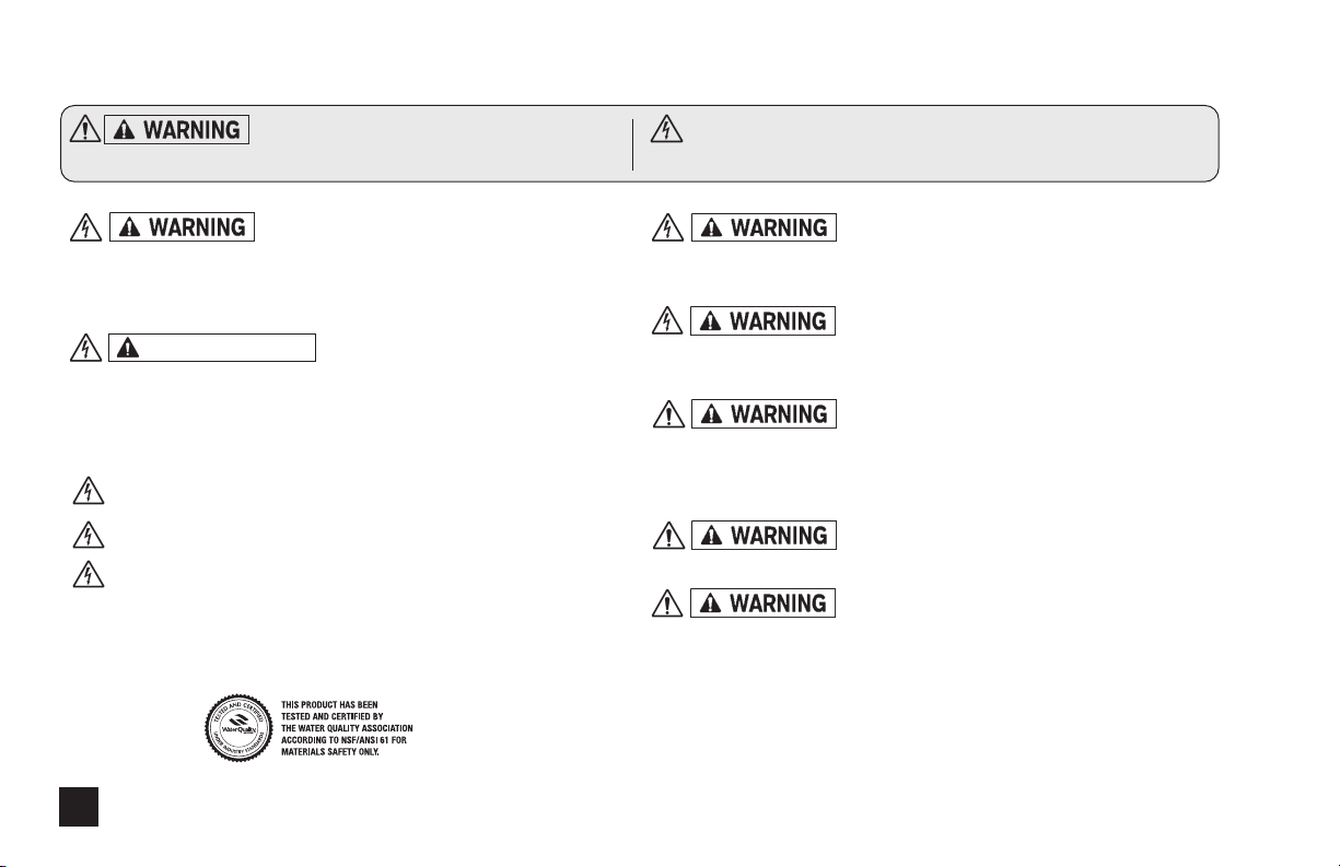
Safety Information
Warns about hazards that CAN cause
death, serious personal injury, or property damage if ignored.
ELECTRIC SHOCK HAZARD:
Pump supplied with grounding power cord and attached plug.
To reduce risk of electrical shock, connect only to a properly
grounded, grounding type receptacle.
AVERTISSEMENT
Cette pompe est équipée d’une fiche de mise à terre. Pour
réduire le risque de choc électrique, s’assurer que la fiche est
bien raccordée à une prise de courant avec une connexion de
mise à terre.
DO NOT alter the power cord or plug end.
DO NOT use receptacle adapters.
DO NOT use pump with a damaged or altered power
cord or plug. Contact the factory or an authorized service facility
for repair.
RISQUE DE CHOC ELECTRIQUE:
ELECTRIC SHOCK HAZARD
HAZARDOUS VOLTAGE:
DISCONNECT power cord before removing motor cover for
service.
Electrical service by trained personnel only.
EXPLOSION HAZARD:
This pump is not explosion proof. Do Not install or operate in
an explosive environment.
RISK OF CHEMICAL EXPOSURE:
Potential for chemical burns, fire, explosion, personal injury, or
property damage. To reduce risk of exposure, the use of proper
personal protective equipment is mandatory.
RISK OF FIRE HAZARD:
Do Not install or operate on any flammable surface.
RISK OF CHEMICAL OVERDOSE:
To reduce risk, follow proper installation methods and
recommendations. Check your local codes for additional
guidelines.
www.stenner.com4
Page 5
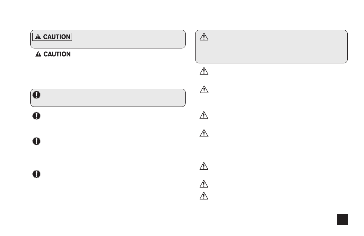
Safety Information continued
Warns about hazards that WILL or CAN
cause minor personal injury or property damage if ignored.
PLUMBING:
Chemical feed pump installation must always adhere to your
local plumbing codes and requirements. Be sure installation does
not constitute a cross connection. Check local plumbing codes
for guidelines.
NOTICE: Indicates special instructions or general
mandatory action.
NOTICE: This metering pump is portable and designed
to be removable from the plumbing system without
damage to the connections.
NOTICE: This metering pump and its components
have been tested for use with the following chemicals:
Sodium Hypochlorite (10-15%), Muriatic Acid (20-22%
Baume, 31.5% Hcl), and Soda Ash.
NOTE: Cette a pompe de dosage et ses composants ont
été testés pour utilisation avec les produits chimiques
suivants; Hypochlorite de Sodium (solution de 10-15%);
Acide Muriatique (20-22% Baume, 31.5% Hcl); Cendre
de Soude.
This is the safety alert symbol. When displayed in
this manual or on the equipment, look for one of the
following signal words alerting you to the potential for
personal injury or property damage.
PUMP SUITABLE FOR USE OUTDOORS when installed
with a Stenner Rain Roof Part No. MP90000.
Electrical installation should adhere to all national and local
codes. Consult a licensed professional for assistance with proper
electrical installation.
Removing power from pool/spa recirculation pump must
also remove power from pump.
The use of an auxiliary safety device (not supplied), such as
a flow switch or sensor, is recommended to prevent feed pump
operation in the event of a recirculation pump failure or if flow
is not sensed.
Point of chemical injection should be beyond all pumps,
filters, and heaters.
PUMP INTENDED FOR INDOOR USE.
Cette pompe est prévue pour utilisation à l’intérieur.
US and Canada call 1.800.683.2378, other countries call 1.904.641.1666 5
Page 6
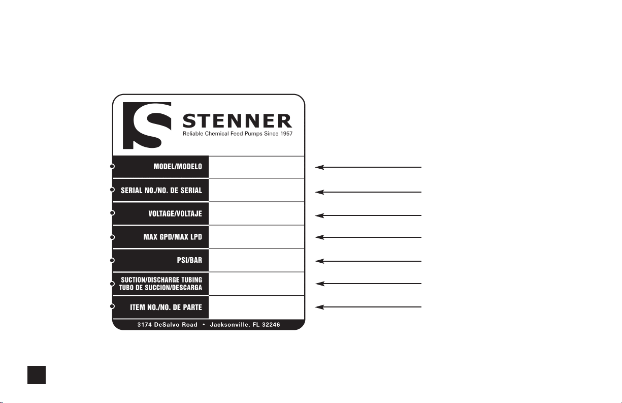
Pump Identification
Identify your pump using the label on the box or the pump.
Box Label
85MHP5
02010503943
120
5/18.9
5/18.9
5/18.9 Ajustable
Adjustable
100/6.9
1/4" White
1/4" Blanco
85MJH1A1STAA
www.stenner.com6
Model
Serial Number
Voltage
Maximum Output per Day
Maximum Operating Pressure
Suction/Discharge Tubing
Item Number for
Placing Order
Page 7
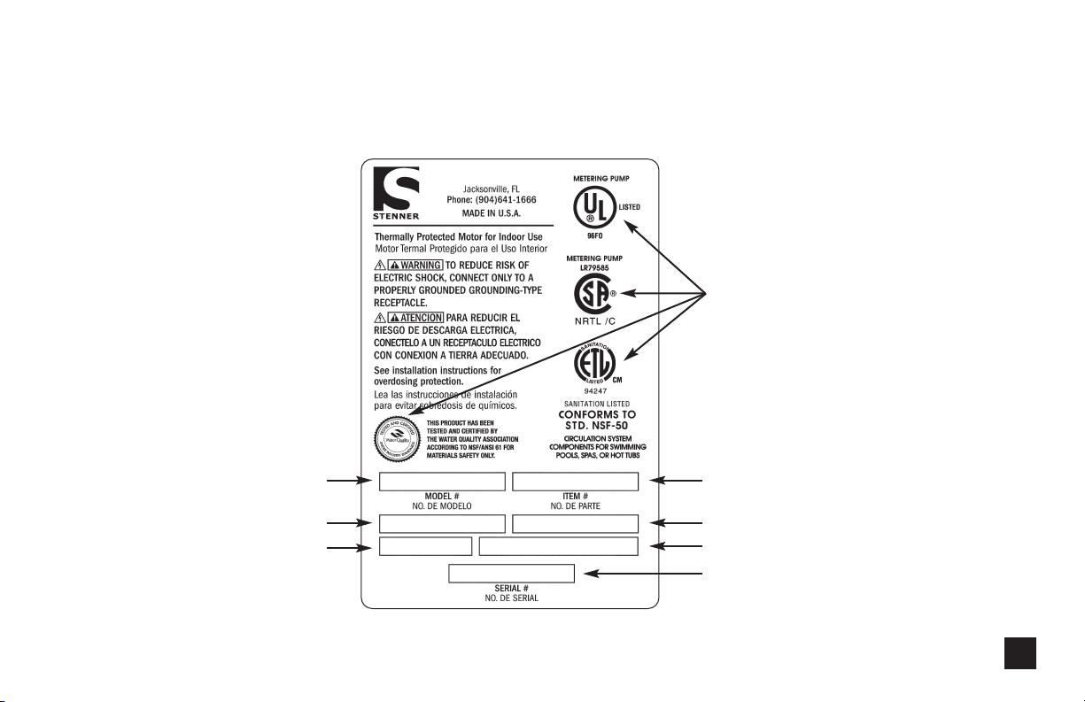
Pump Identification continued
Pump Label
STENNER PUMP COMPANY
Agency Listings
(varies by model)
Model
Maximum Operating Pressure
Amp Draw
US and Canada call 1.800.683.2378, other countries call 1.904.641.1666 7
85MHP5
100 psi / 6.9 bar
1.7 amp
02010503943
85MJH1A1STAA
120VAC / 60Hz
5 GPD / 18.9 LPD
Item Number for
Placing Order
Voltage
Maximum Output per Day
Serial Number
Page 8
Outputs 45 series
The dial ring for adjustable pumps is marked L-10; L=5%, 1-10 indicates
Approx. Outputs @ 60 Hz Approx. Outputs @ 50 Hz
Single Head Maximum Pump Tube gallons liters gallons liters ounces milliliters liters liters milliliters
Model Pressure Number per day per day per hour per hour per minute per minute per day per hour per minute
Adjustable
45MHP2* 100 psi/6.9 bar #1 0.2 to 3.0 0.8 to 11.4 0.01 to 0.13 0.03 to 0.48 0.02 to 0.27 0.56 to 7.92 0.6 to 9.1 0.03 to 0.38 0.31 to 6.32
45M1 25 psi/1.7 bar #1
Fixed Output
45MPHP2* 100 psi/6.9 bar #1 3.0 11.4 0.13 0.48 0.27 7.92 9.1 0.38 6.32
45MP1 25 psi/1.7 bar #1
Adjustable
45MHP10* 100 psi/6.9 bar #2 0.5 to 10.0 1.9 to 37.9 0.02 to 0.42 0.08 to 1.58 0.04 to 0.89 1.32 to 26.32 1.5 to 30.3 0.06 to 1.26 1.04 to 21.04
45M2 25 psi/1.7 bar #2
Fixed Output
45MPHP10* 100 psi/6.9 bar #2 10.0 37.9 0.42 1.58 0.89 26.32 30.3 1.26 21.04
45MP2 25 psi/1.7 bar #2
Adjustable
45MHP22* 100 psi/6.9 bar #7 1.1 to 22.0 4.2 to 83.3 0.05 to 0.92 0.18 to 3.47 0.10 to 1.96 2.92 to 57.85 3.3 to 66.6 0.14 to 2.78 2.29 to 46.25
45M3 25 psi/1.7 bar #3
Fixed Output
45MPHP22* 100 psi/6.9 bar #7 22.0 83.3 0.92 3.47 1.96 57.85 66.6 2.78 46.25
45MP3 25 psi/1.7 bar #3
Adjustable
45M4 25 psi/1.7 bar #4 1.7 to 35.0 6.4 to 132.5 0.07 to 1.46 0.27 to 5.52 0.15 to 3.11 4.44 to 92.01 5.1 to 106.0 0.21 to 4.42 3.54 to 73.61
Fixed Output
45MP4 25 psi/1.7 bar #4 35.0 132.5 1.46 5.52 3.11 92.01 106.0 4.42 73.61
Adjustable
45M5 25 psi/1.7 bar #5 2.5 to 50.0 9.5 to 189.3 0.10 to 2.08 0.40 to 7.89 0.22 to 4.44 6.60 to 131.46 7.6 to 151.4 0.32 to 6.31 5.28 to 105.14
Fixed Output
45MP5 25 psi/1.7 bar #5 50.0 189.3 2.08 7.89 4.44 131.43 151.4 6.31 105.14
*pump supplied with injection check valve for 26-100 psi applications
NOTICE: The information within this chart is solely intended for use as a guide. The output data is an approximation based on pumping water under a controlled testing environment.
Many variables can affect the output of the pump. Stenner Pump Company recommends that all metering pumps undergo field calibration by means of analytical testing to confirm their outputs.
0.2 to 3.0 0.8 to 11.4 0.01 to 0.13 0.03 to 0.48 0.02 to 0.27 0.56 to 7.92 0.6 to 9.1 0.03 to 0.38 0.31 to 6.32
3.0 11.4 0.13 0.48 0.27 7.92 9.1 0.38 6.32
0.5 to 10.0 1.9 to 37.9 0.02 to 0.42 0.08 to 1.58 0.04 to 0.89 1.32 to 26.32 1.5 to 30.3 0.06 to 1.26 1.04 to 21.04
10.0 37.9 0.42 1.58 0.89 26.32 30.3 1.26 21.04
1.1 to 22.0 4.2 to 83.3 0.05 to 0.92 0.18 to 3.47 0.10 to 1.96 2.92 to 57.85 3.3 to 66.6 0.14 to 2.78 2.29 to 46.25
22.0 83.3 0.92 3.47 1.96 57.85 66.6 2.78 46.25
www.stenner.com8
10% increments of maximum output. (20:1 Turndown Ratio)
Page 9
Outputs 85 series
The dial ring for adjustable pumps is marked L-10; L=5%, 1-10 indicates
Approx. Outputs @ 60 Hz Approx. Outputs @ 50 Hz
Single Head Maximum Pump Tube gallons liters gallons liters ounces milliliters liters liters milliliters
Model Pressure Number per day per day per hour per hour per minute per minute per day per hour per minute
Adjustable
85MHP5* 100 psi/6.9 bar #1 0.3 to 5.0 1.1 to 18.9 0.01 to 0.21 0.05 to 0.79 0.03 to 0.44 0.76 to 13.13 0.9 to 15.1 0.4 to 0.63 0.52 to 10.49
85M1 25 psi/1.7 bar #1
Fixed Output
85MPHP5* 100 psi/6.9 bar #1 5.0 18.9 0.21 0.79 0.44 13.13 15.1 0.63 10.49
85MP1 25 psi/1.7 bar #1
Adjustable
85MHP17* 100 psi/6.9 bar #2 0.8 to 17.0 3.0 to 64.4 0.03 to 0.71 0.13 to 2.68 0.07 to 1.51 2.08 to 44.65 2.4 to 51.5 0.10 to 2.15 1.67 to 35.76
85M2 25 psi/1.7 bar #2
Fixed Output
85MPHP17* 100 psi/6.9 bar #2 17.0 64.4 0.71 2.68 1.51 44.65 51.5 2.15 35.76
85MP2 25 psi/1.7 bar #2
Adjustable
85MHP40* 100 psi/6.9 bar #7 2.0 to 40.0 7.6 to 151.4 0.08 to 1.67 0.32 to 6.31 0.18 to 3.55 5.27 to 105.14 6.1 to 121.1 0.25 to 5.05 4.24 to 84.10
85M3 25 psi/1.7 bar #3
Fixed Output
85MPHP40* 100 psi/6.9 bar #7 40 151.4 1.67 6.31 3.55 105.14 121.1 5.05 84.10
85MP3 25 psi/1.7 bar #3
Adjustable
85M4 25 psi/1.7 bar #4 3.0 to 60.0 11.4 to 227.1 0.13 to 2.5 0.48 to 9.46 0.27 to 5.33 7.92 to 157.71 9.1 to 181.7 0.38 to 7.57 6.32 to 126.18
Fixed Output
85MP4 25 psi/1.7 bar #4 60.0 227.1 2.50 9.46 5.33 157.71 181.7 7.57 126.18
Adjustable
85M5 25 psi/1.7 bar #5 4.3 to 85.0 16.3 to 321.8 0.18 to 3.54 0.68 to 13.40 0.38 to 7.55 11.32 to 223.40 13.0 to 257.4 0.54 to 10.73 9.03 to 178.75
Fixed Output
85MP5 25 psi/1.7 bar #5 85.0 321.8 3.54 13.40 7.55 223.40 257.4 10.73 178.75
*pump supplied with injection check valve for 26-100 psi applications
NOTICE: The information within this chart is solely intended for use as a guide. The output data is an approximation based on pumping water under a controlled testing environment.
Many variables can affect the output of the pump. Stenner Pump Company recommends that all metering pumps undergo field calibration by means of analytical testing to confirm their outputs.
0.3 to 5.0 1.1 to 18.9 0.01 to 0.21 0.05 to 0.79 0.03 to 0.44 0.76 to 13.13 0.9 to 15.1 0.4 to 0.63 0.52 to 10.49
5.0 18.9 0.21 0.79 0.44 13.13 15.1 0.63 10.49
0.8 to 17.0 3.0 to 64.4 0.03 to 0.71 0.13 to 2.68 0.07 to 1.51 2.08 to 44.65 2.4 to 51.5 0.10 to 2.15 1.67 to 35.76
17.0 64.4 0.71 2.68 1.51 44.65 51.5 2.15 35.76
2.0 to 40.0 7.6 to 151.4 0.08 to 1.67 0.32 to 6.31 0.18 to 3.55 5.27 to 105.14 6.1 to 121.1 0.25 to 5.05 4.24 to 84.10
40 151.4 1.67 6.31 3.55 105.14 121.1 5.05 84.10
US and Canada call 1.800.683.2378, other countries call 1.904.641.1666 9
10% increments of maximum output. (20:1 Turndown Ratio)
Page 10
Outputs 100 series
The dial ring for adjustable pumps is marked L-10; L=5%, 1-10 indicates
Approx. Outputs @ 60 Hz Approx. Outputs @ 50 Hz
Double Head Maximum Pump Tube gallons liters gallons liters ounces milliliters liters liters milliliters
Model Pressure Number per day per day per hour per hour per minute per minute per day per hour per minute
Adjustable
100DMHP5* 100 psi/6.9 bar #1 0.3 to 6.0 1.1 to 22.7 0.01 to 0.25 0.05 to 0.95 0.03 to 0.53 0.76 to 15.76 0.9 to 18.2 0.04 to 0.76 0.61 to 12.64
100DM1 25 psi/1.7 bar #1
Fixed Output
100DMPHP5* 100 psi/6.9 bar #1 6.0 22.7 0.25 0.95 0.53 15.76 18.2 0.76 12.64
100DMP1 25 psi/1.7 bar #1
Adjustable
100DMHP20* 100 psi/6.9 bar #2 1.0 to 20.0 3.8 to 75.7 0.04 to 0.83 0.16 to 3.15 0.09 to 1.78 2.64 to 52.57 3.0 to 60.6 0.13 to 2.53 2.11 to 42.06
100DM2 25 psi/1.7 bar #2
Fixed Output
100DMPHP20* 100 psi/6.9 bar #2 20.0 75.7 0.83 3.15 1.78 52.57 60.6 2.53 42.06
100DMP2 25 psi/1.7 bar #2
Adjustable
100DM3 25 psi/1.7 bar #3 2.2 to 44.0 8.3 to 166.5 0.09 to 1.83 0.35 to 6.94 0.19 to 3.91 5.76 to 115.63 6.6 to 133.2 0.28 to 5.55 4.58 to 92.50
Fixed Output
100DMP3 25 psi/1.7 bar #3 44.0 166.5 1.83 6.94 3.91 115.63 133.2 5.55 92.50
Adjustable
100DM4 25 psi/1.7 bar #4 3.5 to 70.0 13.2 to 265.0 0.15 to 2.92 0.55 to 11.04 0.31 to 6.22 9.17 to 184.03 10.6 to 212.0 0.44 to 8.83 7.36 to 147.22
Fixed Output
100DMP4 25 psi/1.7 bar #4 70.0 265.0 2.92 11.04 6.22 184.03 212.0 8.83 147.22
Adjustable
100DM5 25 psi/1.7 bar #5 5.0 to 100.0
Fixed Output
100DMP5 25 psi/1.7 bar #5 100.0 378.5 4.17 15.77 8.88 262.88 302.8 12.61 210.28
*pump supplied with injection check valve for 26-100 psi applications
NOTICE: The information within this chart is solely intended for use as a guide. The output data is an approximation based on pumping water under a controlled testing environment.
Many variables can affect the output of the pump. Stenner Pump Company recommends that all metering pumps undergo field calibration by means of analytical testing to confirm their outputs.
0.3 to 6.0 1.1 to 22.7 0.01 to 0.25 0.05 to 0.95 0.03 to 0.53 0.76 to 15.76 0.9 to 18.2 0.04 to 0.76 0.61 to 12.64
6.0 22.7 0.25 0.95 0.53 15.76 18.2 0.76 12.64
1.0 to 20.0 3.8 to 75.7 0.04 to 0.83 0.16 to 3.15 0.09 to 1.78 2.64 to 52.57 3.0 to 60.6 0.13 to 2.53 2.11 to 42.06
20.0 75.7 0.83 3.15 1.78 52.57 60.6 2.53 42.06
18.9 to 378.5 0.21 to 4.17 0.79 to 15.77 0.44 to 8.88 13.13 to 262.88 15.1 to 302.8 0.63 to 12.61 10.49 to 210.28
10% increments of maximum output. (20:1 Turndown Ratio)
www.stenner.com10
Page 11
Outputs 170 series
The dial ring for adjustable pumps is marked L-10; L=5%, 1-10 indicates
Approx. Outputs @ 60 Hz Approx. Outputs @ 50 Hz
Double Head Maximum Pump Tube gallons liters gallons liters ounces milliliters liters liters milliliters
Model Pressure Number per day per day per hour per hour per minute per minute per day per hour per minute
Adjustable
170DMHP9* 100 psi/6.9 bar #1 0.5 to 10.0 1.9 to 37.9 0.02 to 0.42 0.08 to 1.58 0.04 to 0.89 1.32 to 26.32 1.5 to 30.3 0.06 to 1.26 1.04 to 21.04
170DM1 25 psi/1.7 bar #1
Fixed Output
170DMPHP9* 100 psi/6.9 bar #1 10.0 37.9 0.42 1.58 0.89 26.32 30.3 1.26 21.04
170DMP1 25 psi/1.7 bar #1
Adjustable
170DMHP34* 100 psi/6.9 bar #2 1.7 to 34.0 6.4 to 128.7 0.07 to 1.42 0.27 to 5.36 0.15 to 3.02 4.44 to 89.38 5.1 to 103.0 0.21 to 4.29 3.54 to 71.55
170DM2 25 psi/1.7 bar #2
Fixed Output
170DMPHP34* 100 psi/6.9 bar #2 34.0 128.7 1.42 5.36 3.02 89.38 103.0 4.29 71.55
170DMP2 25 psi/1.7 bar #2
Adjustable
170DM3 25 psi/1.7 bar #3 4.0 to 80.0 15.1 to 302.8 0.17 to 3.33 0.63 to 12.62 0.35 to 7.11 10.49 to 210.28 12.1 to 242.2 0.50 to 10.09 8.40 to 168.22
Fixed Output
170DMP3 25 psi/1.7 bar #3 80.0 302.8 3.33 12.62 7.11 210.28 242.2 10.09 168.22
Adjustable
170DM4 25 psi/1.7 bar #4 6.0 to 120.0
Fixed Output
170DMP4 25 psi/1.7 bar #4 120.0 454.2 5.00 18.93 10.66 315.42 363.4 15.14 252.36
Adjustable
170DM5 25 psi/1.7 bar #5 8.5 to 170.0 32.2 to 643.5 0.35 to 7.08 1.34 to 26.8 0.76 to 15.10 22.36 to 446.88 25.7 to 514.8 1.07 to 21.45 17.92 to 357.50
Fixed Output
170DMP5 25 psi/1.7 bar #5 170.0 643.6 7.08 26.8 15.10 446.88 514.8 21.45 357.50
*pump supplied with injection check valve for 26-100 psi applications
NOTICE: The information within this chart is solely intended for use as a guide. The output data is an approximation based on pumping water under a controlled testing environment.
Many variables can affect the output of the pump. Stenner Pump Company recommends that all metering pumps undergo field calibration by means of analytical testing to confirm their outputs.
0.5 to 10.0 1.9 to 37.9 0.02 to 0.42 0.08 to 1.58 0.04 to 0.89 1.32 to 26.32 1.5 to 30.3 0.06 to 1.26 1.04 to 21.04
10.0 37.9
1.7 to 34.0 6.4 to 128.7 0.07 to 1.42 0.27 to 5.36 0.15 to 3.02 4.44 to 89.38 5.1 to 103.0 0.21 to 4.29 3.54 to 71.55
34.0 128.7 1.42 5.36 3.02 89.38 103.0 4.29 71.55
22.7 to 454.2 0.25 to 5.00 0.95 to 18.93 0.53 to 10.66 15.76 to 315.42 18.2 to 363.4 0.76 to 15.14 12.64 to 252.36
0.42 1.58 0.89 26.32 30.3 1.26 21.04
10% increments of maximum output. (20:1 Turndown Ratio)
US and Canada call 1.800.683.2378, other countries call 1.904.641.1666 11
Page 12

Outputs 100 MDC series
Determining Output for Dual Head Dual
Control Models
• The dial ring for adjustable pumps is marked
L-10; L=5%, 1-10 indicates 10% increments of
maximum output.
• The turndown ratio is 20:1.
• On the MDC models, the outer pump head
operates on a percentage of the inner head
(closest to the motor).
• Setting #10 on both pump heads will deliver the
pump’s maximum output and is the only time each
pump head will output the same amount.
Example Using 100MDC5
• Decide on the desired output for the inner head.
• Note the setting on the dial ring that represents the
desired output.
For example setting #4 = 40% of max output
In the 100MDC5 model, setting #4 = 20 GPD
• Repeat the above steps to calculate the output of the
outer head.
Using setting #3 in this example,
#3 = 30% of the inside head output
20 GPD x 30% = 6 GPD
In this example using pump model 100MDC5,
the output for the inside head would be 20 GPD
and 6 GPD for the outside head.
www.stenner.com12
Page 13
Outputs 100 MDC series
The dial ring for adjustable pumps is marked L-10; L=5%, 1-10 indicates
10% increments of maximum output. (20:1 Turndown Ratio)
Outputs for Inner Pump Head Only
Approx. Outputs @ 60 Hz Approx. Outputs @ 50 Hz
Dual Head Maximum Pump Tube gallons liters gallons liters ounces milliliters liters liters milliliters
Dual Control Pressure Number per day per day per hour per hour per minute per minute per day per hour per minute
Model
Adjustable
100MDCHP5* 100 psi/6.9 bar #1 0.2 to 3.0 0.8 to 11.4 0.01 to 0.13 0.03 to 0.48 0.02 to 0.27 0.56 to 7.92 0.6 to 9.1 0.03 to 0.38 0.42 to 6.32
100MDC1 25 psi/1.7 bar #1
100MDCHP20* 100 psi/6.9 bar #2 0.5 to 10.0 1.9 to 37.9 0.02 to 0.42 0.08 to 1.58 0.04 to 0.89 1.32 to 26.32 1.5 to 30.3 0.06 to 1.26 1.04 to 21.04
100MDC2 25 psi/1.7 bar #2
100MDC3 25 psi/1.7 bar #3 1.1 to 22.0 4.2 to 83.3 0.05 to 0.92 0.18 to 3.47 0.10 to 1.96 2.92 to 57.85 3.3 to 66.6 0.14 to 2.78 2.29 to 46.25
100MDC4 25 psi/1.7 bar #4 1.7 to 35.0 6.4 to 132.5 0.07 to 1.46 0.27 to 5.52 0.15 to 3.11 4.44 to 92.01 5.1 to 106.0 0.21 to 4.42 3.54 to 73.61
100MDC5 25 psi/1.7 bar #5 2.5 to 50.0 9.5 to 189.3 0.10 to 2.08 0.40 to 7.89 0.22 to 4.44 6.60 to 131.46 7.6 to 151.4 0.32 to 6.31 5.28 to 105.14
*pump supplied with injection check valve for 26-100 psi applications
NOTICE: The information within this chart is solely intended for use as a guide. The output data is an approximation based on pumping water under a controlled testing environment.
Many variables can affect the output of the pump. Stenner Pump Company recommends that all metering pumps undergo field calibration by means of analytical testing to confirm their outputs.
0.2 to 3.0 0.8 to 11.4 0.01 to 0.13 0.03 to 0.48 0.02 to 0.27 0.56 to 7.92 0.6 to 9.1 0.03 to 0.38 0.42 to 6.32
0.5 to 10.0 1.9 to 37.9 0.02 to 0.42 0.08 to 1.58 0.04 to 0.89 1.32 to 26.32 1.5 to 30.3 0.06 to 1.26 1.04 to 21.04
US and Canada call 1.800.683.2378, other countries call 1.904.641.1666 13
Page 14

Outputs 170 MDC series
Determining Output for Dual Head Dual
Control Models
• The dial ring for adjustable pumps is marked
L-10; L=5%, 1-10 indicates 10% increments of
maximum output.
• The turndown ratio is 20:1.
• On the MDC models, the outer pump head
operates on a percentage of the inner head
(closest to the motor).
• Setting #10 on both pump heads will deliver the
pump’s maximum output and is the only time each
pump head will output the same amount.
Example Using 170MDCHP34
• Decide on the desired output for the inner head.
• Note the setting on the dial ring that represents the
desired output.
For example setting #8 = 80% of max output
In the 170MDCHP34 model, setting
#8 = 13.6 GPD
• Repeat the above steps to calculate the output of the
outer head.
Using setting #6 in this example,
#6 = 60% of the inner head output
13.6 GPD x 60% = 8.5 GPD
In this example using pump model 170MDCHP34, the
output for the inner head would be 13.6 GPD and
8.5 GPD for the outer head.
www.stenner.com14
Page 15
Outputs 170 MDC series
The dial ring for adjustable pumps is marked L-10; L=5%, 1-10 indicates
10% increments of maximum output. (20:1 Turndown Ratio)
Outputs for Inner Pump Head Only
Approx. Outputs @ 60 Hz Approx. Outputs @ 50 Hz
Dual Head Maximum Pump Tube gallons liters gallons liters ounces milliliters liters liters milliliters
Dual Control Pressure Number per day per day per hour per hour per minute per minute per day per hour per minute
Model
Adjustable
170MDCHP9* 100 psi/6.9 bar #1 0.3 to 5.0 1.1 to 18.9 0.01 to 0.21 0.05 to 0.79 0.03 to 0.44 0.76 to 13.13 0.9 to 15.1 0.4 to 0.63 0.63 to 10.49
170MDC1 25 psi/1.7 bar #1
170MDCHP34* 100 psi/6.9 bar #2 0.8 to 17.0 3.0 to 64.4 0.03 to 0.71 0.13 to 2.68 0.07 to 1.51 2.08 to 44.65 2.4 to 51.5 0.10 to 2.15 1.67 to 35.76
170MDC2 25 psi/1.7 bar #2
170MDC3 25 psi/1.7 bar #3 2.0 to 40.0 7.6 to 151.4 0.08 to 1.67 0.32 to 6.31 0.18 to 3.55 5.27 to 105.14 6.1 to 121.1 0.25 to 5.05 4.24 to 84.10
170MDC4 25 psi/1.7 bar #4 3.0 to 60.0 11.4 to 227.1 0.13 to 2.5 0.48 to 9.46 0.27 to 5.33 7.92 to 157.71 9.1 to 181.7 0.38 to 7.57 6.32 to 126.18
170MDC5 25 psi/1.7 bar #5 4.3 to 85.0 16.3 to 321.8 0.18 to 3.54 0.68 to 13.40 0.38 to 7.55 11.32 to 223.40 13.0 to 257.4 0.54 to 10.73 9.03 to 178.75
*pump supplied with injection check valve for 26-100 psi applications
NOTICE: The information within this chart is solely intended for use as a guide. The output data is an approximation based on pumping water under a controlled testing environment.
Many variables can affect the output of the pump. Stenner Pump Company recommends that all metering pumps undergo field calibration by means of analytical testing to confirm their outputs.
0.3 to 5.0 1.1 to 18.9 0.01 to 0.21 0.05 to 0.79 0.03 to 0.44 0.76 to 13.13 0.9 to 15.1 0.4 to 0.63 0.63 to 10.49
0.8 to 17.0 3.0 to 64.4 0.03 to 0.71 0.13 to 2.68 0.07 to 1.51 2.08 to 44.65 2.4 to 51.5 0.10 to 2.15 1.67 to 35.76
US and Canada call 1.800.683.2378, other countries call 1.904.641.1666 15
Page 16

Materials of Construction
All Housings* . . . . . . . . . . . . . . . . . Lexan®Polycarbonate Plastic
Peristaltic Tube** . . . . . . . . . . . . . . Santoprene®FDA Approved
Check Valve Duckbill
Peristaltic Tube
Check Valve Duckbill††. . . . . . . . . . Pellathane
Suction/Discharge Tubing . . . . . . . . LDPE Polyethylene-NSF/FDA Approved
Ferrules (1/4" & 6mm)
Tube Fittings . . . . . . . . . . . . . . . . . Type 1 Rigid PVC-NSF Listed
Connecting Nuts
Check Valve Fittings
Weighted Suction Line Strainer
All Fasteners . . . . . . . . . . . . . . . . . Stainless Steel
†
. . . . . . . . . . . . . . . Tygothane®FDA Approved
®
*Lexan®is a registered trademark of General Electric.
Consult General Electric for chemical resistance of Lexan
**Santoprene
Elastomer System, Akron, OH.
®
is a registered trademark of Advanced
†
Tygothane®is a registered trademark of Saint-Gobain
®
.
Performance Plastics, Pittsburgh, PA.
††
Pellathane®is a registered trademark of The Dow
Company, Midland, MI.
www.stenner.com16
Page 17

Accessory Checklist – pre-installation
25 psi unit includes:
(3) Connecting Nuts (1/4" or 3/8")
(3) Ferrules w/1/4" & 6mm or
(2) Ferrules w/3/8"
(1) Injection Fitting
(1) Weighted Suction Line Strainer 1/4", 3/8" or 6mm
(1) 20' Roll of Suction & Discharge Tubing
1/4" or 3/8" white or UV black
OR
6mm (Europe) white
(1) Spare Pump Tube
(1) Mounting Bracket
(1) Installation Manual
100 psi unit includes:
(3) Connecting Nuts (1/4" or 3/8")
(3) Ferrules w/1/4" & 6mm or
(2) Ferrules w/3/8"
(1) Injection Check Valve
(1) Weighted Suction Line Strainer 1/4", 3/8" or 6mm
(1) 20' Roll of Suction & Discharge Tubing
1/4" or 3/8" white or UV black
OR
6mm (Europe) white
(1) Spare Pump Tube
(1) Mounting Bracket
(1) Installation Manual
US and Canada call 1.800.683.2378, other countries call 1.904.641.1666 17
Page 18

Installation – additional safety instructions
NOTICE: Indicates special instructions or general mandatory action.
Read all safety hazards before installing or
servicing the pump. The pump is designed
for installation and service by properly
trained personnel.
Use all required personal protective
equipment when working on or near
a chemical metering pump.
Install the pump so that it is in compliance
with all national and local plumbing and
electrical codes.
www.stenner.com18
Use the proper product to treat
potable water systems, use only
chemicals listed or approved for use.
Install the pump to work in
conjunction with pool, spa,
well pump, or system controls.
Page 19

Installation continued – mount pump
MOUNT PUMP
Select a dry location (to avoid water
intrusion and pump damage) above the
solution tank. Best recommended location
is above the solution tank in a vertical
position with the pump head pointed
downward and the spill recovery (see
next page) in place to reduce the risk and
severity of damage.
To prevent pump damage in the event of
a pump tube leak, never mount the pump
vertically with the pump head up.
To avoid chemical damage from fumes,
do not mount pump directly over an open
solution tank. Keep tank covered.
Avoid flooded suction or pump mounted
lower than the solution container.
Draw solution from the top of the tank.
If pump is installed with a flooded
suction, a shut-off valve or other device
must be provided to stop flow to pump
during service.
US and Canada call 1.800.683.2378, other countries call 1.904.641.1666 19
1. Use the mounting bracket as a template
to drill pilot holes in mounting location.
2. Secure bracket with fasteners or wall
anchors. Slide pump into bracket.
Provide 8" clearance to allow pump
orientation to be reversed during tube
replacement. Do not allow water intrusion
into the motor or corrosion and damage
will occur.
To prevent motor damage, verify with a
volt meter that the receptacle voltage
corresponds with the pump voltage.
3. Plug cord into receptacle and turn the
motor power switch on. If the pump is
adjustable, turn the dial ring to 10.
4. Activate the pump by the pump control
(flow switch, pressure switch, etc.) and
verify rotation of the roller assembly
within the clear pump head. Turn pump
switch off.
Rain roof
(optional)
slips onto
wall bracket
Wall
bracket
Pump
head
Page 20

Installation continued – additional instructions for CE pumps
Additional
Installation
Instructions
1. All Class II Pumps located
in Zone 1 of swimming
pool areas require
locating where flooding
cannot occur.
2. This pump is intended to
be installed as “fixed” as
opposed to portable.
3. The Rain Roof must be
installed and “vertical
orientation” mounting of
entire unit observed.
4. After installation, the
power supply plug must
be accessible during use.
5. This unit must be
scrapped if the supply
cord is damaged.
6. Observe and comply with
all National Wiring
Standards.
Zustazliche
Installierungsanweisung
un
1. Pumpen die sich in Zone 1
vom Schwimmbecken
befinden sollen sind so
einzurichten daß
Ueberschwemmungen
nicht vorkommen werden.
2. Diese Pumpe ist als fest
montierte Ausrustung
bedacht und soll nicht
umstellbar gebraucht
werden.
3. Der Regendach muss
installiert werden. Eine
vertikale Asrichtung der
Montage muß erzielt
werden.
gung muss
omversor
4. Die Str
nach der Installierung
noch zuganglich sein.
5. Bei beschadigter
Verkabelung ist dieses
Gerat nicht mehr zu
gebrauchen.
6. Staatliche
Vernetzungsvorchriften
mussen eingehalten
werden.
Instructions
Supplémentaires
d’Installtion
1. Toutes les pompes
installées dans la Zone 1
du périmètre de la
piscine doivent être
situées de manière à ne
pas pouvoir être
inondées.
2. Cette pompe est prévue
pour installation fixe et
non pas portative.
3. L’abri anti-pluie doit être
installé et l’orientation
verticale doit toujours
être observée.
4. Après l’installation, la
prise électrique doit
rester accessible pendant
l’utilisation.
5. Cette unité doit être mise
au rebut si le cordon
électrique est
endommagé.
6. Observez et adhérez à
toutes les Normes
Nationales pour
Installations Electriques.
Instucciones
Adicionales Para
instalación
1. Todas las bombas Clase II
situadas en la Zona 1 de
las áreas de la piscina
requieren colocarse
donde no puedan ser
inundadas.
2. Esta bomba es para ser
instalada “fija” en vez
de portátil.
3. Es necesario instalar el
techo de lluvia, y montar
la unidad entera
siguiendo una orintación
vertical.
4. Depués de la instalación
el enchufe suministrador
de energia debe estar
accesible durante el uso.
5. Se deberá desechar la
unidad si el cordón de
abastecimiento se
deteriora.
6. Observe y cumpla con
todas las Reglas
Nacionales para
Instalaciones Eléctricas.
Istruzioni
Supplementari Per
L’ installazione
1. Tutte le pompe Classe II
localizzate nella Zona 1
della superficie
circostante la piscina
devono essere collocate
dove gli allagamenti no
possono accadere.
2. Questa pompa, é inteso,
deve essere installata
come ‘fissa’ e non come
portatile.
3. La tettoia deve essere
installata e il montaggio
‘orientazione verticale’
dell’intera unitá deve
essere osservato.
4. Dopo l’installazione, la
spina deve essere
accessibile durante l’uso.
5. Questa unitá deve essere
gettata via se il filo
elettrico é danneggiato.
6. Osservare e aderire a
tutte le Norme Nazionali
Sugli Impianti Elettrici.
www.stenner.com20
Page 21

Installation Diagram
Rain roof slips onto
slots in the wall
mounting bracket.
(No tools necessary)
On/Off Switch
(Under roof – not
visible this view)
Wall Mounting
Bracket (Requires
2 screws)
IN
Disassembled
View
(Suction)
OUT
(Discharge)
Always use rain roof for
outdoor use
or
if metering pump is
subject to washdowns.
Grounded Power
Outlet (GFIC
recommended)
Shut-Off
Valve
Duckbill
Disassembled
View
Injection
Check Valve
26-100 psi
Injection
Fitting
0-25 psi
Solution
Tank
Injection
Check
Valve
Injection
Tube
US and Canada call 1.800.683.2378, other countries call 1.904.641.1666 21
Page 22

Installation continued – spill recovery
SPILL RECOVERY
In case of tube rupture, chemical
drains back into solution tank,
preventing spillage onto
ground/floor and stops chemical
from collecting in tube housing.
Spill recovery tube
drains solution
back to tank.
Partial hole is punched through
with a #2 Phillips head screwdriver.
1/4" plastic spill recovery tube is
inserted in hole. Use section of
suction/dischar
ge tubing.
Spill
Recovery
Tube
Strainer
w/weight
www.stenner.com22
Page 23

Installation continued – suction line
INSTALL SUCTION LINE
1. Uncoil the suction line and cut a section
to assure that the end will be 2-3" above
the bottom of the solution tank. Use the
outside of the solution tank as a guide to
cut to proper length.
Allow sufficient slack to avoid kinks
and stress cracks. Always make a clean
square cut to assure that the suction
line is burr free. Normal maintenance
requires trimming.
Suction lines that extend to the bottom
of the tank can result in debris pickup
leading to clogged injectors and possible
tube failure.
2. Slide the suction line through the
connecting nut and ferrule and fully insert
the line into the bottom pump tube
fitting as indicated by the “IN” on the
tube housing cover.
3. Finger tighten nut to the threaded tube
fitting while holding the tube fitting.
Over tightening the ferrule and nut
with a wrench may result in damaged
fittings, crushed ferrules, and air pickup.
Do not use thread sealant tape on
pump tube connections or tools to
tighten connections.
More on next page…
DO NOT use Teflon
tape on pump
tube threads.
Finger
tighten
nut
Ferrules
Suction
line
DO NOT
use pliers.
OUT
IN
Note: Beveled ends of
ferrules face pump.
Tubing should bottom
into all fittings.
US and Canada call 1.800.683.2378, other countries call 1.904.641.1666 23
Page 24

Installation continued – suction line
4. Drill a 17/64" hole into the lid or bung cap of the solution tank. Secure
strainer weight to the end of the suction line as per provided instructions
and feed it into the hole.
5. Suspend 2-3" above the tank bottom.
Strainer
w/weight
Strainer
w/weight
(closeup view)
Strainer w/weight
(disassembled view)
Do not mix chemicals in the
solution container. Follow
recommended mixing procedures
according to the manufacturer.
www.stenner.com24
Do not operate pump unless
chemical is completely in solution.
Turn pump off when replenishing
solution.
Page 25

Installation continued – discharge line
INSTALL DISHARGE LINE
1. Make a secure finger tight connection
on the discharge fitting of the pump
head as instructed in Install Suction
Line instructions.
Do not use thread sealant tape on pump
tube connections or tools to tighten
connections.
HAZARDOUS PRESSURE:
Shut off water or circulation system and bleed
off any system pressure.
Locate a point of injection beyond all
pumps and filters or as determined by
the application.
2. A 1/4" or 1/2" female NPT connection is
required for the injection fitting. If there
is no FNPT fitting available, provide one
by either tapping the pipe or installing
FNPT pipe tee fitting.
3. Wrap MNPT end of injection fitting
with 2 to 3 turns of threading tape. If
necessary trim straight-sided extension
tip so it is in the flow of water.
See Illustration
4. Tighten the injection fitting into the
FNPT fitting.
More on next page…
DO NOT use Teflon
tape on pump
tube threads.
Trimming
Check Valves
DO NOT
use pliers.
US and Canada call 1.800.683.2378, other countries call 1.904.641.1666 25
Page 26

Installation continued – discharge line
Typical Point of Injection
Shut-Off
Valve
1/4'' or 1/2''
Injection
Check
Valve
FNPT Reduction
Bushing
HAZARDOUS PRESSURE:
Shut off water or circulation system
and bleed off any system pressure.
The injection point and fitting require
periodic maintenance to clean any
deposits or buildup. To allow quick access
to the point of injection, Stenner
recommends the installation of shut-off
valves.
26-100 psi models:
• Prior to making tubing connection, test
check valve and NPT threads for leaks by
pressurizing system.
• Tighten an additional 1/4 turn if
necessary. Make final tube connection
as instructed in Install Suction Line
instructions.
0-25 psi models:
Low-pressure models do not have a check
valve and check valve body. Insert the
tubing 3/4" to 1" into the injection fitting
and make tubing connection as instructed
in Install Suction Line instructions.
5. Turn pump switch on and observe
chemical flow as actuated by system.
6. After a suitable amount of dosing time,
perform tests for required chemical levels.
If necessary, fine-tune dosing levels by
rotating dial ring (adjustable pumps only).
www.stenner.com26
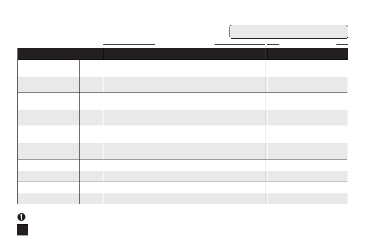
Page 27

Troubleshooting – motor
PROBLEM POSSIBLE CAUSE SOLUTION
Motor HAZARDOUS VOLTAGE:
DISCONNECT power cord before removing motor cover for service. Electrical service should be
by trained personnel only.
Noise is excessively loud. Ball bearings are worn. Replace rotor assembly.
Lubrication is insufficient. Grease gears and gear posts.
Gears or gear posts are worn. Inspect/replace gears and gear posts.
Motor does not work; fan is not turning. Electrical supply is faulty. Check supply voltage circuit.
Rotor bound to coil. Check bearing brackets for cracks and replace if necessary.
Motor coil is damaged. Replace motor coil.
Motor bearings are worn or damaged. Replace rotor assembly.
Power cord is damaged. Inspect/replace power cord.
Rotor rusted to coil. Clean off coil and rotor or replace as needed.
Wire connections are faulty. Inspect/repair electrical connections.
Fan is obstructed. Remove obstruction.
Motor runs; fan turns; output shaft does not. Check all gears. Replace gears as needed.
Motor overheats and shuts off and on. Voltage is incorrect. Check that voltage and frequency match data label.
Ambient temperature is high. Install pump in an area not to exceed a maximum of 125˚ F.
Coil is damaged/malfunctioning. Replace motor coil.
Phenolic gear is stripping. Water intrusion. Use rain roof.
Cracked bearing bracket. Replace bearing bracket.
Gear posts worn. Replace gear posts.
Rusted helical gear at end of rotor. Buff off rotor or replace rotor.
Worn gear case cover. Replace gear case cover.
Insufficient lubrication. Lubricate with AquaShield
®
.
US and Canada call 1.800.683.2378, other countries call 1.904.641.1666 27
Page 28

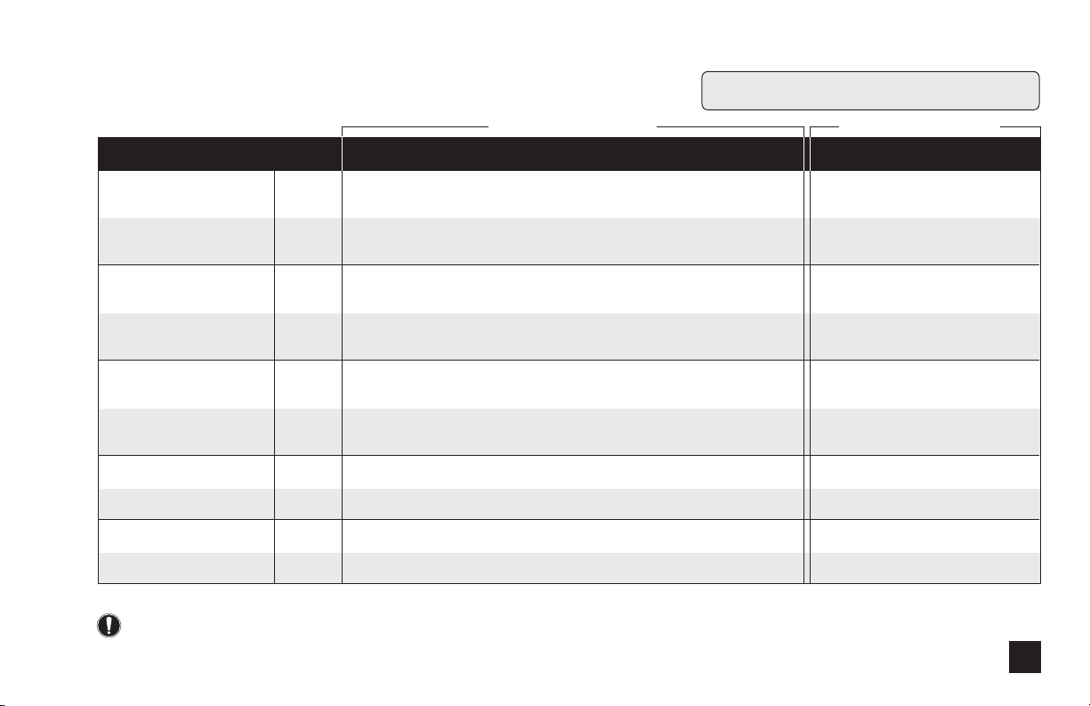
Troubleshooting continued – feed rate control
PROBLEM POSSIBLE CAUSE SOLUTION
Feed Rate Control
Adjustment ring will not turn. Variable cam has seized. Grease variable cam and cam slot.
Adjustment ring has seized. Clean and lubricate ring.
Adjustment ring turns, output doesn’t change. Variable cam has disengaged from ring. Re-insert 90˚ end into ring.
Variable cam is broken. Replace variable cam.
Pump head is not rotating. Index plate is worn. Turn over or replace index plate.
Problem with the gear motor. Refer to Motor Section.
Pump head roller assembly is stripped. Replace roller assembly.
Index pin holder backed out of
spider assembly. Tighten holder into spider assembly.
Index pin is broken. Replace index pin and lifter assembly.
Pump head rotates continuously. Variable cam is installed incorrectly. Replace or re-insert variable cam.
Indexing is erratic. Index plate is worn. Turn over or replace index plate.
Variable cam is worn. Replace variable cam.
Lifter is worn. Replace index pin and lifter assembly.
www.stenner.com28
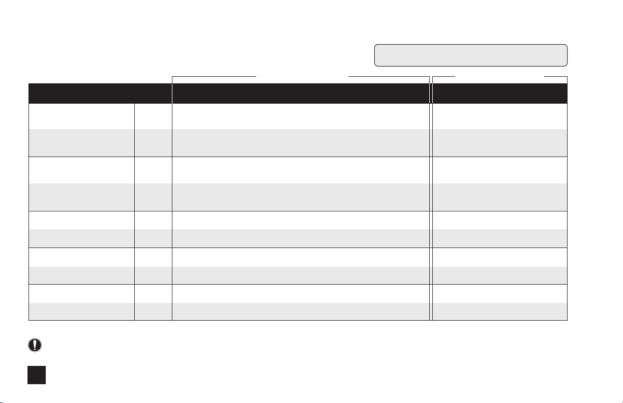
Page 29

Troubleshooting continued – pump head
PROBLEM POSSIBLE CAUSE SOLUTION
Pump Head
Components are cracking. Chemical attack. Check chemical compatibility.
Visible fluid in pump head. Pump tube rupture/leak. Replace pump tube and ferrules and center tube.
No pump output; pump head rotates. Depleted solution tank. Replenish solution.
Pump suction line weight is above solution. Maintain suction line 2-3" off bottom of tank.
Suction line leak. Inspect or replace suction line.
Ferrules installed incorrectly or damaged. Replace compression ferrules.
Injection point is clogged. Inspect and clean injection point.
Clogged suction/discharge tubing and/or
injection check valve. Clean and/or replace as necessary.
Life of pump tube is exhausted. Replace pump tube.
Low pump output; pump head rotates. Pump tube is worn. Replace pump tube.
Rollers missing or cracked. Install new rollers or roller assembly.
Injection point is restricted. Inspect and clean injection point.
High system back pressure. Check tube psi rating against system pressure; replace accordingly.
No pump output; Roller assembly is stripped. Replace roller assembly.
pump head not rotating. Feed Rate Control problem. Refer to Feed Rate Control section.
Motor problem. Refer to Motor section.
Pump output is high. Incorrect tube size. Replace tube with correct size.
Roller assembly is broken. Replace roller assembly.
Malfunctioning Feed Rate Control. Refer to Feed Rate Control section.
Incorrect model of motor. Replace with proper motor.
US and Canada call 1.800.683.2378, other countries call 1.904.641.1666 29
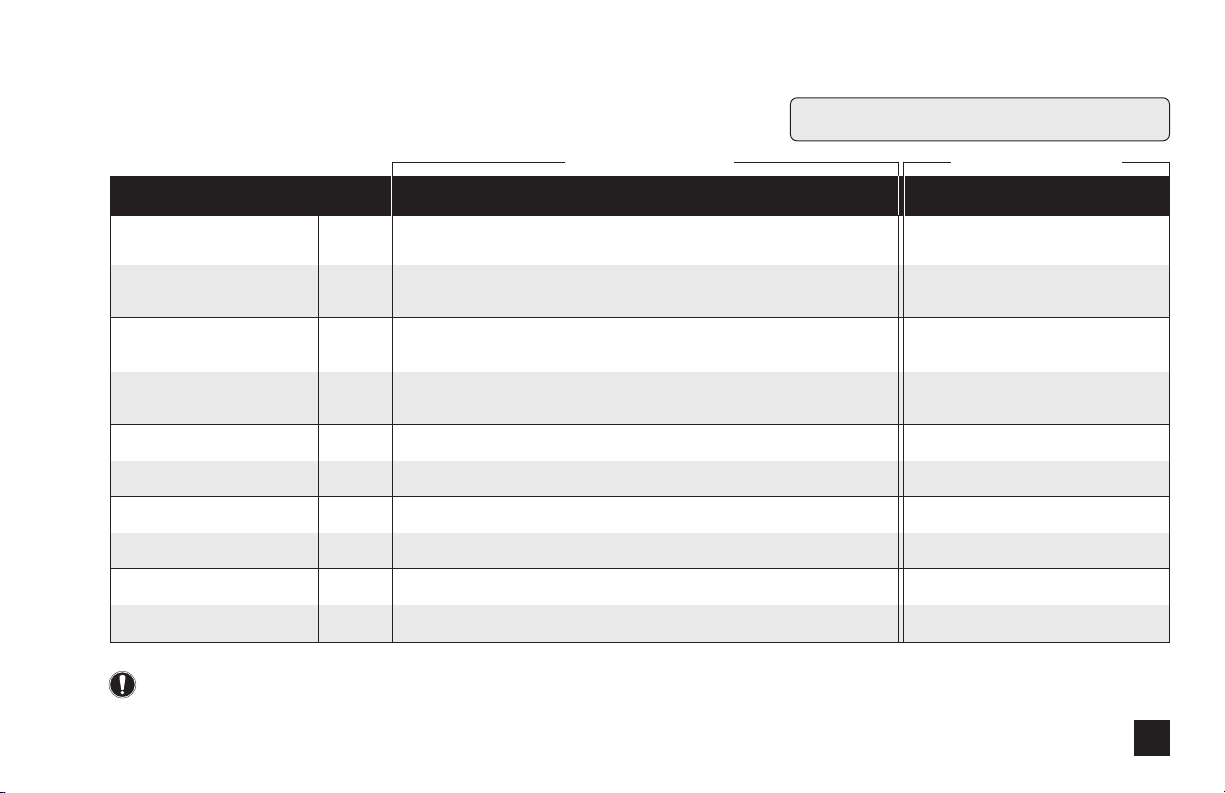
Page 30

Troubleshooting continued – pump tube
PROBLEM POSSIBLE CAUSE SOLUTION
Pump Tube NOTICE: A leaking pump tube damages the metering pump. Inspect pump frequently for leakage
Tube is leaking. Pump tube has ruptured. Replace pump tube at routine intervals.
Tube life is shortened. Chemical attack. Check chemical compatibility.
and wear. Refer to Tube Replacement section for additional safety precautions and instructions.
Calcium or mineral deposit. Clean injection fitting, replace pump tube.
Excessive back pressure. Check tube psi rating against system pressure;
Tube is twisted. Replace tube according to instructions.
Tube is not centered. Replace tube and center it.
Mineral deposit at injection point. Remove deposit and replace pump tube.
Sediment blockage at check valve. Maintain suction line 2-3" above bottom of tank.
Degraded check valve duckbill. Replace check valve duckbill at every tube change.
Duckbill in wrong orientation. Reverse duckbill orientation.
Tube was manually stretched to lock See tube replacement instructions. Allow roller
into discharge side slot. assembly to stretch tube into place.
Seized rollers caused abrasion on tube. Clean roller assembly or replace.
www.stenner.com30
replace accordingly.
Use a suction line strainer.
Page 31

Tube Replacement – safety information
RISK OF CHEMICAL EXPOSURE:
To reduce risk of exposure, check the pump tube
regularly for leakage. At the first sign of leakage,
replace the pump tube.
To reduce risk of exposure, the use of proper personal
protective equipment is mandatory when working on or
near chemical metering pumps.
To reduce risk of exposure, and also prior to service,
shipping, or storage, pump generous amounts of
water or a compatible buffer solution to remove
chemical from pump.
Consult chemical manufacturer and MSDS sheet for
additional information and precautions for the chemical
in use.
Personnel should be skilled and trained in the proper
safety and handling of the chemicals in use.
PINCH POINT HAZARD:
Use extreme caution when replacing pump tube.
Be careful of your fingers and
fingers near rollers.
US and Canada call 1.800.683.2378, other countries call 1.904.641.1666 31
DO NOT place
HAZARDOUS PRESSURE/CHEMICAL
EXPOSURE:
Use caution and bleed off all resident system pressure
prior to attempting service or installation.
Use caution when disconnecting discharge tubing from
pump. Discharge may be under pressure. Tubing may
contain chemical.
NOTICE: Indicates special instructions or general
mandatory action.
NOTICE: DO NOT apply grease, oil, or lubricants to the
pump tube or housing.
NOTICE: Prior to pump tube replacement, inspect the entire
pump head for cracks or damaged components. Ensure rollers
turn freely.
NOTICE: Rinse off chemical r
debris from pump head components prior to tube replacement.
Apply Stenner grease to main shaft and tube housing cover
bushing during tube replacement.
esidual and clean all chemical and
NOTICE: DO NOT pull excessively on pump tube. Avoid
kinks or damage during tube installation.
NOTICE: Inspect the suction/discharge tubing, injection point
(into pipe), and injection check valve duckbill for blockages
after any tube rupture. Clear or replace as required.
Page 32

Tube Replacement continued – preparation
1. Follow all safety precautions prior to tube
replacement.
2. Prior to service, pump water or a compatible buffer
solution through the pump and suction/discharge line
to remove chemical and avoid contact.
3. Turn pump off.
4. Disconnect the suction and discharge connections
from pump head.
5. Plug power cord into constantly energized, properly
grounded receptacle for service.
www.stenner.com32
Page 33

Tube Replacement continued – remove old tube
REMOVE OLD TUBE
1. Remove and set aside cover and screws.
2. Set feed rate dial on the low setting
until finished.
3. Turn pump on and let it run until one of
three roller assembly slots lines up with
the tube fitting on the suction side.
Illustration A
4. Turn pump off.
5. Lift tube fitting out of housing slot and
pull it toward center of roller assembly.
Illustration B
6. Turn pump on and allow roller assembly
to jog while guiding tube, with tension,
up and out of housing.
7. Turn pump off. Remove and discard
pump tube.
Illustration C
8. Remove roller assembly, shaft, and
housing.
9. Use non-citrus all-purpose cleaner to clean
chemical residue from pump head housing,
roller, and cover.
10. Check housing for cracks. Replace if
cracked.
11. Ensure rollers spin freely. Illustration D
12. Replace roller assembly if: seized, excessive
side play from bore wear, or if rollers are
visibly worn.
13. Reinstall clean tube housing.
14. Grease shaft tip and install.
15. Install roller assembly.
A
Pull Out
B
Pull Out
C
D
Check
Rollers
US and Canada call 1.800.683.2378, other countries call 1.904.641.1666 33
Page 34

Tube Replacement continued – install new tube
IMPORTANT! Do not lubricate
pump tube or roller assembly.
E
Tube
Housing
Slot
Roller Assembly
Slot
F
Guide
Turn the pump
on, walk tube in.
G
Guide
Tube
Housing
NOTE: Cover screws are self-tapping and must be
backed in to locate original thread before securing.
If a screw boss is stripped, use alternate bosses
and position opposite from each other. Never
secure the cover plate with more than 2 screws.
Slot
Roller Assembly
Slot
INSTALL NEW TUBE
1. By manually rotating the roller assembly
counter clockwise, align one of three
roller assembly slots with the suction side
housing slot.
2. Place tube fitting into suction side slot of
the housing and the roller assembly slot.
Illustration E
3. With pump setting on low, hold tube
fitting and jog roller assembly by turning
pump on.
IMPORTANT! Avoid rotating wrist, which can
result in a twisted tube that will not center. Do
not force tube and be careful of your fingers.
4. Guide tube, with slight tension (toward
the center) to prevent pinching between
housing and roller assembly.
Illustration F
5. When tube reaches the top housing slot,
turn pump off.
6. Turn dial ring to setting 10, hold tube
fitting firmly, and turn pump on.
NOTE: A used tube will have stretched
approximately 3/4" and the new tube will
appear to be stiff and short. Follow directions
to allow rollers to stretch tube into place.
7. Allow rollers to stretch tube into place
while guiding tube into slot.
Illustration G
8. Turn pump off.
9. Apply a small amount of grease
(AquaShield
®
) to cover bushing ONLY and
replace cover and two screws, leaving front
screw in-between the fittings loose.
www.stenner.com34
Page 35

Tube Replacement continued – center new tube
CENTER NEW TUBE
1. To center pump tube on rollers, set feed
rate dial to setting 10. Turn pump on.
Illustration H
2. Turn the tube fitting on the suction
side not more than 1/8 of a turn in the
direction tube must move.
TUBE CHANGE FOR FIXED OUTPUT PUMP
1. To install a new tube in a fixed output
pump, follow the instructions above and
utilize the on/off switch to jog the roller
assembly in the absence of the feed rate
control.
Illustration I
3. Do not let go of fitting until tube rides
approximately in center of rollers.
4. Turn pump off, let go of fitting, and
tighten cover screws. Cover is not on
securely if there is a gap between screw
boss and cover.
H
1/8
Tur n
Leave this
screw loose.
I
US and Canada call 1.800.683.2378, other countries call 1.904.641.1666 35
Page 36

Motor – exploded view
Rain Roof
Toggle
Switch
Motor Cover
with cord
Coil Screw “G”
w/Lock Washer
On-Off
Switch Plate
Switch
Boot
Motor
Base
Power Cord
Strain Relief
Bushing
Mounting
Bracket
Rotor Assembly with
Bearings, Brackets,
Tolerance Rings & Fan
Coil
www.stenner.com36
Gear Case
Gear
Post
Thrust
Washer
Phenolic
Gear
Metal
Reduction
Gear
Phenolic
Gear Spacer
Motor
Shaft
Gear Case Cover
Pressure Spring
(adjustable
models only)
Cover
Screw “B”
Page 37

Motor continued – subassemblies
MOTORS
DESCRIPTION PART NUMBER UM PART NUMBER UM
Motor 60Hz (adjustable output 45 & 100 series) (120v) PM6041D EA (220v) PM6042D EA
Motor 60Hz (adjustable output 85 & 170 series) (120v) PM6081D EA (220v) PM6082D EA
Motor 60Hz (fixed output 45MP series only) (120v) ME6041D EA (220v) ME6042D EA
Motor 60Hz (fixed output 85MP series only) (120v) ME6081D EA (220v) ME6082D EA
Motor 60Hz (fixed output 100DMP series only) (120v) DM6041D EA (220v) DM6042D EA
Motor 60Hz (fixed output 170DMP series only) (120v) DM6081D EA (220v) DM6082D EA
EUROPE
Motor 50Hz (adjustable output 45 & 100 series) (230v) PM64230 EA (250v) PM6426D EA
Motor 50Hz (adjustable output 85 & 170 series) (230v) PM68230 EA (250v) PM6826D EA
Motor 50Hz (fixed output 45MP series only) (230v) ME64230 EA (250v) ME6426D EA
Motor 50Hz (fixed output 85MP series only) (230v) ME68230 EA (250v) ME6826D EA
Motor 50Hz ((fixed output 100DMP series only) (230v) DM64230 EA (250v) DM64250 EA
Motor 50Hz (fixed output 170DMP series only) (230v) DM68230 EA (250v) DM68250 EA
US and Canada call 1.800.683.2378, other countries call 1.904.641.1666 37
Motor
Page 38

Motor continued – service kits
Motor Service Kit
Wire Nuts
Rotor Assembly w/Bearings,
Brackets, Tolerance Rings & Fan
Gear Case Service Kit
AquaShield
Metal
Reduction
Gear
Gear Posts
®
Coil Screw “G”
w/Lock Washer
Coil
Coil
Phenolic Gear
w/Spacer
Coil Ground
Screw “E”
Motor
Shaft
w/Gear
Cover
Screw “B”
MOTOR SERVICE KITS
DESCRIPTION PART NUMBER UM PART NUMBER UM
Motor Service Kit 60Hz (120v) MSK120 Kit (220v) MSK220 Kit
GEAR CASE SERVICE KITS
DESCRIPTION PART NUMBER UM
Gear Case Service Kit
(adjustable output 45 & 100) GSK45A Kit
Gear Case Service Kit
(adjustable output 85 & 170) GSK85A Kit
Gear Case Service Kit
(fixed output 45MP series only) GSK45F Kit
Gear Case Service Kit
(fixed output 85MP series only) GSK85F Kit
www.stenner.com38
Page 39

Feed Rate Control – exploded view
FRC Screw
Index
Index Pin
Holder
Index Pin
Lifter
Pin Spring
Index Pin
Index Plate
O-Ring
Seal
Feed Rate
Housing
Mounting Rivet
Main Shaft Single Head/
Adjustable Output
Feed Rate
Mounting
Plate
Dial Ring
Variable
Cam
Index Spider
Main Shaft Double
Head/Adjustable Output
Main Shaft Dual Head
Dual Control/Adjustable
Output
Roller Clutch
Contact factory for part numbers.
US and Canada call 1.800.683.2378, other countries call 1.904.641.1666 39
Page 40

Feed Rate Control continued – subassemblies & service kits
Feed Rate
Control
Feed Rate Control Service Kit
AquaShield
Index Plate
Lifter
®
Variable Cam
Screw “A”
FEED RATE CONTROLS
DESCRIPTION PART NUMBER UM
Feed Rate Control w/ shaft
(single head – 45/85 adjustable) FC5040D EA
Feed Rate Control w/ shaft
(double head – 100/170 adjustable) DM5040D EA
Feed Rate Control w/shaft
(dual head dual control – 100/170MDC) DM504DC EA
FEED RATE CONTROL SERVICE KIT
DESCRIPTION PART NUMBER UM
Feed Rate Control Service Kit FSK100 Kit
www.stenner.com40
Page 41

Pump Head – exploded view
Tube Housing
Roller
Housing
Roller
Pump
Tube
Tube Housing
Cover
Cover
Screw “B”
Contact factory for part numbers.
US and Canada call 1.800.683.2378, other countries call 1.904.641.1666 41
Page 42

Pump Head continued – subassemblies
PUMP HEADS
DESCRIPTION PART NUMBER UM PART NUMBER UM
Pump Head
Pump Tube Numbers
#1 and #2 for 26-100 psi pump
(when used with check valve).
#1, 2, 3, 4, 5 for 0-25 psi pump.
#7 tube for 26-100 psi single
head pump only.
Pump Head includes SANTOPRENE
pump tube; ferrules 1/4" * select tube number 1, 2, 3, 4, 5, 7
Pump Head includes SANTOPRENE
pump tube & duckbill; ferrules 1/4" * select tube number 1, 2, 7
Pump Head includes TYGOTHANE
pump tube; ferrules 1/4" * select tube number 2, 5
Pump head includes TYGOTHANE
#2 pump tube; PELLATHANE®duckbill;
ferrules 1/4"
EUROPE
Pump Head includes SANTOPRENE
pump tube; ferrules 6mm * select tube number 1, 2, 3, 4, 5, 7
Pump Head includes SANTOPRENE
pump tube & duckbill; ferrules 6mm * select tube number 1, 2, 7
Pump Head includes TYGOTHANE
pump tube; ferrules 6mm * select tube number 2, 5
Pump head includes TYGOTHANE
#2 pump tube; PELLATHANE®duckbill;
ferrules 6mm
®
®
®
®
®
®
®
®
UCTHC * D EA MCTHC * D PK of 2
UCPH * FD EA n/a n/a
UCPHT0 * EA n/a n/a
UCPHTD2 EA n/a n/a
UCTH * CE EA MCTH * CE PK of 2
UCPH * CE EA n/a n/a
UCPHT * CE EA n/a n/a
UCPHD2CE EA n/a n/a
www.stenner.com42
Page 43

Pump Head continued – service kits
PUMP HEAD SERVICE KITS
DESCRIPTION PART NUMBER UM
SANTOPRENE®Kit (0-25 psi) PSKL0_*_ KIT
* select tube number 1, 2, 3, 4, 5
SANTOPRENE®Kit (26 - 100 psi) PSKH0_*_ KIT
* select tube number 1, 2, 7
TYGOTHANE®Kit (0-25 psi) PSKLT * KIT
* select tube number 2 or 5
KIT: (26-100 psi) TYGOTHANE®#2 Pump Tube PSKHT2 KIT
& PELLATHANE®duckbill included
EUROPE
SANTOPRENE®Kit (1.7 bar) PSKL * CE KIT
* select tube number 1, 2, 3, 4, 5
SANTOPRENE®Kit (1.7-6.9 bar) PSKH *
* select tube number 1, 2, 7
TYGOTHANE®Kit (1.7 bar) PSKLT * CE KIT
* select tube number 2 or 5
KIT: TYGOTHANE®#2 Pump Tube & PSKHT2CE KIT
PELLATHANE®duckbill included
CE
KIT
Roller Assembly
Roller
Assembly
0-25 psi/1.7 bar
Connecting
Nuts 1/4"
Pump Tube
26-100 psi/6.9 bar
Connecting
Nuts 1/4"
Duckbill
Pump Tube
Ferrules 1/4" or
6mm Europe
Cover
Screw “B”
Ferrules 1/4" or
6mm Europe
Cover Screw “B”
US and Canada call 1.800.683.2378, other countries call 1.904.641.1666 43
Page 44

Adapter Pump Heads – subassemblies
ADAPTER PUMP HEADS
DESCRIPTION PART NUMBER UM PART NUMBER UM
®
®
®
®
®
®
®
®
Adapter
Pump
Head
Adapter Pump Head includes SANTOPRENE
pump tube; ferrules 1/4" * select tube number 1, 2, 3, 4, 5
Adapter Pump Head includes SANTOPRENE
pump tube & duckbill; ferrules 1/4" * select tube number 1, 2
Adapter Pump Head includes TYGOTHANE
pump tube; ferrules 1/4" * select tube number 2, 5
Adapter Pump Head includes #2 TYGOTHANE
pump tube PELLATHANE®duckbill; ferrules 1/4"
EUROPE
Adapter Pump Head includes SANTOPRENE
pump tube; ferrules 6mm * select tube number 1, 2, 3, 4, 5
Adapter Pump Head includes SANTOPRENE
pump tube & duckbill; ferrules 6mm * select tube number 1, 2
Adapter Pump Head includes TYGOTHANE
pump tube; ferrules 6mm * select tube number 2, 5
Adapter Pump Head includes #2 TYGOTHANE
pump tube; PELLATHANE®duckbill; ferrules 6mm
UC1ATC * EA MC1ATC * PK of 2
UCAH * FD EA n/a n/a
UCAHT0 * EA n/a n/a
UCAHTD2 EA n/a n/a
UCAP * CE EA MCAP * CE PK of 2
UCAH * CE EA n/a n/a
UCAT *
CE
EA n/a n/a
UCT2DCE EA n/a n/a
www.stenner.com44
Page 45

Pump Tubes
PUMP TUBES
DESCRIPTION PART NUMBER UM PART NUMBER UM
SANTOPRENE®Pump Tube UCCP20 * PK of 2 MCCP20 * PK of 5
ferrules 1/4" * select tube number 1, 2, 3, 4, 5, 7
SANTOPRENE®Pump Tube & duckbill; UCCP * FD PK of 2 n/a n/a
ferrules 1/4" * select tube number 1, 2, 7
TYGOTHANE®Pump Tube; UCTYG0 * PK of 2 MCTYG0 * PK of 5
ferrules 1/4" * select tube number 2, 5
TYGOTHANE®#2 Pump Tube & UCTY2FD PK of 2 n/a n/a
PELLATHANE®duckbill; ferrules 1/4"
EUROPE
SANTOPRENE®Pump Tube UCCP2 * CE PK of 2 MCCP2 * CE PK of 5
ferrules 6mm * select tube number 1, 2, 3, 4, 5, 7
®
SANTOPRENE
ferrules 6mm * select tube number 1, 2, 7
TYGOTHANE®Pump Tube UCTY * CE PK of 2 MCTY * CE PK of 5
ferrules 6mm * select tube number 2, 5
TYGOTHANE
PELLATHANE®duckbill; ferrules 6mm
Pump Tube & duckbill; UC * FDCE PK of 2 n/a n/a
®
#2 Pump Tube & UCTY2DCE PK of 2 n/a n/a
Pump Tube Numbers
#1 and #2 for 26-100 psi pump
(when used with check valve).
#1, 2, 3, 4, 5 for 0-25 psi pump.
#7 tube for 26-100 psi single
head pump only.
US and Canada call 1.800.683.2378, other countries call 1.904.641.1666 45
Page 46

Check Valves
Injection Check Valve 1/4"
CHECK VALVES
DESCRIPTION PART NUMBER UM PART NUMBER UM
Check Valve includes SANTOPRENE
duckbill; ferrules 1/4"
Check Valve includes PELLATHANE
duckbill; ferrules 1/4"
®
®
UCDBINJ EA MCDBINJ PK of 5
UCTYINJ EA MCTYINJ PK of 5
Injection Check Valve 3/8"
Injection Check Valve 6mm
Check Valve includes SANTOPRENE
duckbill; ferrules 3/8"
Check Valve includes PELLATHANE
duckbill; ferrules 3/8"
EUROPE
Check Valve includes SANTOPRENE
duckbill; ferrules 6mm
Check Valve includes PELLATHANE
duckbill; ferrules 6mm
www.stenner.com46
®
®
®
®
UCINJ38 EA MCINJ38 PK of 5
UCTYIJ38 EA MCTYIJ38 PK of 5
UCINJCE EA MCINJCE PK of 5
UCTINJCE EA MCTINJCE PK of 5
Page 47

For Your Records
Model:
Serial Number:
Date of Installation:
US and Canada call 1.800.683.2378, other countries call 1.904.641.1666 47
Page 48

Metering Pumps
Manufactured Since 1957
3174 DeSalvo Road
Jacksonville, Florida 32246
sales@stenner.com
www.stenner.com
Phone: 904.641.1666
US Toll Free: 800.683.2378
Fax: 904.642.1012
Hours of Operation (EST):
Mon. – Thu. 7am – 5pm
Friday 7am – Noon
 Loading...