

Watts SunStat Pro II 500775BB, SunStat Pro II 500775WB, SunStat Pro II 500775HB, SunStat Pro II 500775SB, SunStat Pro II 500775 Nstallation & Operation Manual
Page 1
Installation &
Operation Manual
SunStat® Pro II
Programmable Thermostat
Model 500775 (-BB, -HB, -SB, -WB)
Local building or electrical codes may require modifications to the information
provided. You are required to consult the local building and electrical codes
prior to installation. If this information is not consistent with local building or
electrical codes, the local codes should be followed.
Items included
Unpack the thermostat control and make sure every thing is in good condition.
Do not use a damaged control or part. The package comes with these items:
(1) Thermostat
(1) Thermostat Floor Sensor
(5) Wire Nuts (Marettes®)
(2) Mounting Screws
(1) Screwdriver
Tools and supplies needed
• No. 2 Phillips screwdriver
• Hole saw (if installing in an existing wall)
• Wire strippers, wire cutters, and other electrical tools
• Electrical wall box (plastic or metal)*
*A single-gang extra-deep box allows sufficient space to connect 1 or 2
heating mats or cables. For 3 heating mats or cables, a 4-inch square extradeep electrical box with a single-gang “mud ring” is necessary. Alternately,
a junction box may be installed to connect multiple heating mats or cables,
then run power supply wire from the junction box to the control electrical
box. See the Installation Instructions provided with the floor heating system
for more details.
The SunStat Pro II model 500775 is designed to operate either a 120 VAC or
240 VAC resistance floor heating system. It comes with an easy setup wizard, a
typical Program Schedule ready to go, and a GFCI inside to meet safety needs.
Read this Manual BEFORE using this equipment.
Failure to read and follow all safety and use
information can result in death, serious personal
injury, property damage, or damage to the
equipment.
Keep this Manual for future reference.
Installation must be performed by qualified personnel, in accordance with
local codes and standards. A licensed electrician is recommended.
As with any electrical product, care should be taken to guard
against the potential risk of fire, electric shock, and injury to
persons. The following must be observed:
• Wire all circuits as Class 1, Electric Light and Power Circuits.
• Wire all circuits with insulation rated 600V minimum.
• Mount this control only to a grounded metallic box or a nonmetallic box.
• Use power supply wires suitable for at least 90°C.
• High voltage – disconnect power supply before servicing.
The GFCI (ground-fault circuit interrupter) in this thermostat control does not
•
protect against shock if both bare conductors are touched at the same time.
•
Do not exceed 15 amps on this thermostat control. Doing so will cause risk
of fire hazard and damage.
• Make sure the house power supply voltage matches the voltage rating of
the floor heating system. Do not apply 240 VAC to a 120 VAC rated system.
Connecting the wrong voltage may cause overheating and damage to the
system, the control, floor coverings, etc.
Installation
Locating the Control
Find a suitable location for the control. Consider the following:
• It is designed for indoor dry location only.
• It may be placed on an insulated or uninsulated wall, preferably an interior
wall to avoid overheating from outside sun heat.
Keep it away from all water sources such as sinks, showers, and bathtubs
•
as well as heat sources such as hot-water piping, heat ducting, wall-mount
lighting, and direct sunlight.
Locate it at a suitable height, normally about 4-1/2’ to 5’ (1.4 m to 1.5 m)
•
from the floor.
Mounting the Electrical Box
•
When mounting on an existing wall, cut the opening for the electrical box for
the control. To make it easier to pull the wiring, wait to install the electrical
box until after all wiring is drawn into this opening.
• When mounting on an open wall, secure the electrical box for the control to
the wall stud. Conduit from the electrical box to the floor is recommended
(check local codes for requirements) for additional protection. Install one
conduit for the floor sensor. Install another conduit for the floor heating
system power leads.
• Refer to the Installation Instructions supplied with the floor heating system
for additional installation details.
Wiring
To prevent the risk of p ersonal injur y and/or death, make sure
power is not applied to the product until it is fully installed and
ready for final testing. All work must be done with power turned
off to the circuit being worked on.
House Wiring
Pull power supply wiring to the control location. Consider the following:
• Leave about 6 to 8 inches (15 to 20 cm) of wire for connections later.
This wiring should be size 12 or 14 AWG following appropriate local code
•
requirements.
A qualified person should run a dedicated circuit from the main circuit
•
breaker panel to the control location. If a dedicated circuit is not possible, it
is acceptable to tap into an existing circuit. However, there must be enough
capacity to handle the load (amps) of the floor heating system being installed
and any possible appliance, such as a hair dryer or vacuum cleaner.
• Avoid circuits that have ballasted lighting, motors, exhaust fans, or hot tub
pumps due to possible interference.
The circuit breaker should be rated 20 amps for total circuit loads up to 15 amps.
•
A 15 amp circuit breaker may be used for total circuit loads up to 12 amps.
A GFCI (ground-fault circuit interrupter) or AFCI (arc-fault circuit interrupter)
•
type circuit breaker may be used if desired, but is not necessary.
Page 2
Floor Sensor
1. Test the Thermostat Floor Sensor included to make sure it has not been
damaged in handling. Use a digital multimeter set to the 20kΩ range. The
resistance varies according to the temperature sensed. These are approximate
values for reference:
Table 1 – Sensor resistances
Temperature Typical Values
55°F (13°C) 17 kΩ
65°F (18°C) 13 kΩ
75°F (24°C) 10 kΩ
85°F (29°C) 8 kΩ
2. Pull the floor sensor wire up the wall (or conduit) to the control location.
Consider the following:
• Leave about 6 to 8 inches (15 to 20 cm) of wire for connections later.
• The sensor wire may be cut shorter if desired, but do not cut it shorter until
the sensor is fully installed (see below). Re-strip the sensor wire ends 1/8” to
3/16” (3 mm to 4.5 mm) long. If the ends are stripped longer than this they
may short-circuit resulting in an Err2 code.
• If the sensor wire is not long enough to reach the control location, it may be
extended an additional 15 feet (4.5 m) using minimum 20 AWG 2-conductor
unshielded wire, or an additional 50 feet (15 m) using shielded wire. When
using shielded wire, the “shield” must be connected to the lower sensor
terminal, nearest to Bus A. A junction box may be required by local code for
the connection to this extension wire.
3. After the floor heating system is completely installed according to its
instructions, secure the thick sensor tip to the floor. Consider the following:
It must be located halfway between heating wires and at least 1 foot into
•
the heating area.
• Use hot-glue to secure the sensor tip and wire in place.
• Do not cross over a heating wire.
•
Avoid placing it in an area where heating wires are spaced further apart than
the rest of the floor, like a large gap between mats or cables.
•
Avoid placing it in an area where a heat duct or recessed light will cause
improper measurements.
Try to avoid locating it where future items such as a clothes hamper or similar
•
could trap heat and cause improper measurement.
Power Leads from Heating Mat or Cable
Pull the power lead wires from the floor heating system into the control location.
Excess power lead wire may be cut off, but leave about 6 to 8 inches (15 to 20
cm) of wire for connections.
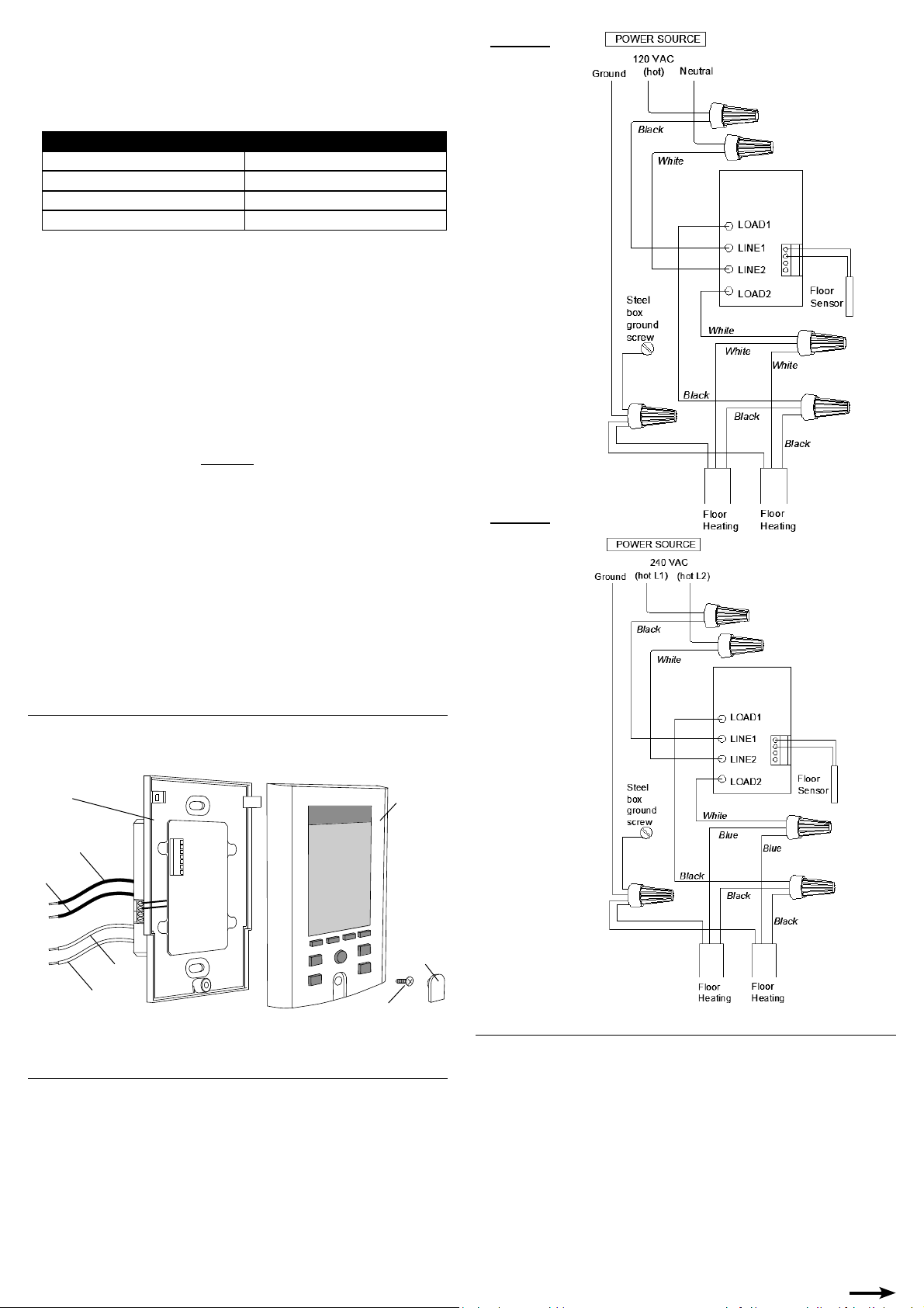
Figure 1
Figure 2
Removing the Thermostat Front Module
1. Remove the Screw Cover at the bottom and loosen the screw.
2. Lift the Front Module away from the Power Module.
Power Module
Load 1
Line 1
Floor Sensor
Connection
Line 2
Load 2
Cover Screw
Front
Module
Screw
Cover
Wiring Connections (see Figure 1 and 2)
Connect the wires as shown in the diagram. Consider the following:
•
Gently tug on the wires to make sure they are secure. For added security,
overwrap the Wire Nut connections with electrical tape.
• If the electrical box is metal, a short length of wire must be secured to the
electrical box from the ground connection.
When connecting the Floor Sensor to the Sensor terminals, it does not matter
•
which wire goes into which terminal.
The Bus A and B terminals are used to communicate with a SunStat Relay
•
II. Please read and follow the instructions provided with the SunStat Relay
II for further details.
Mounting the Thermostat
1. Make sure the power supply to the circuit is turned off at the circuit breaker.
2. Carefully press the wires back into the electrical box.
•
DO NOT use the control to push wires in, as this may cause connections to
loosen and possible failure.
3. Use the Mounting Screws provided to secure to the electrical box and tighten
by hand.
DO NOT over-tighten the screws causing the plastic to distort, as this may
•
cause improper function of the thermostat.
4. Press the Front Module onto the Power Module. Make sure both tabs at the
top are completely engaged.
• DO NOT install the Front Module with power applied on the Power Module,
as this may cause improper function of the thermostat.
5. Secure the screw at the bottom and replace the Screw Cover.
• DO NOT over-tighten the screw causing it to strip. Turn it until snug.
Page 3

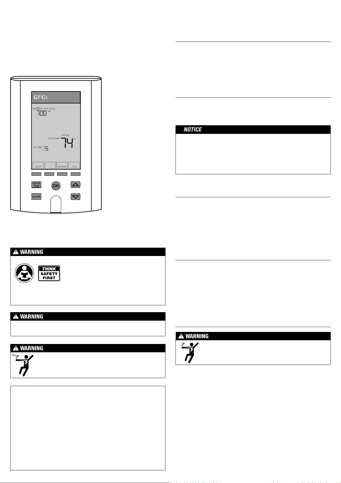
Operation
Overview
Day
Time
Floor temperature
Setpoint temperature
Press a button if the display is dark. This
wakes the display backlight.
An Interactive Tutorial is also available
on the website to help.
On/Off and Reset
Pressing
to clear an error or GFCI fault. See “GFCI Testing” and “Troubleshooting”.
Startup
When first powered on, the thermostat begins a “startup wizard” to help the
user through basic setup. For each setting, press or buttons to adjust
and press
1. Set the year, month, day, hour, and minutes.
2. Select the sensing method (Floor or Air). Recommended is “FLOOR TEMP”.
3. Select a Pre-Programmed Schedule. Recommended is “NORMAL DAY” where
4. Press
Table 2 - Pre-Programmed Schedules – Customize to fi t your needs
Air Sensing mode default temperatures are 70°F and 62°F.
GFCI Testing
The GFCI (Ground Fault Circuit Interrupter) in this control must be tested when
installation is finished and once each month.
1. Make sure the control shows “HEATING”. This may require temporarily
2. Press the
3. To reset the GFCI TRIP, press the
Adjusting the Temperature
Temporary Adjustment
1. Press or buttons to adjust the setpoint temperature and press
2. Pressing
on/off
will turn the thermostat on or off. This also resets the thermostat
OK
to accept.
it makes the floor warmer during morning and evening hours. Any of the
schedules can be customized later to fit your needs.
OK
and the thermostat will begin working automatically.
NORMAL DAY
74°F
(23. 3°C)
74°F
(23. 3°C)
74°F
(23. 3°C)
WARM ALL NIGHT
74°F (
23.3°C)
74°F (
23.3°C)
23.3°C)
74°F (
HOME DURING DAY
-- --
-- --
-- --
82°F
82°F
82°F
82°F (
82°F (
82°F (
(27.8°C)
(27.8°C)
(27.8°C)
27.8°C)
27.8°C)
27.8°C)
74°F
74°F
74°F
74°F
74°F
74°F
(23. 3°C)
(23. 3°C)
(23. 3°C)
--
--
--
(23. 3°C)
(23. 3°C)
(23. 3°C)
Monday-
Friday
Saturday
Sunday
Monday-
Friday
Saturday
Sunday
Monday-
Friday
Saturday
Sunday
WAKE LEAVE RETURN SLEEP
6:00 AM 8:00 AM 5:00 PM 10:00 PM
82
°
F
(27.8°C)
7:00 AM 9:00 AM 5:00 PM 11:00 PM
°
F
(27.8°C)
82
7:00 AM 9:00 AM 5:00 PM 11:00 PM
°
F
(27.8°C)
82
WAKE LEAVE RETURN SLEEP
-- 8:00 AM 5:00 PM --
--
-- 9:00 AM 5:00 PM --
--
-- 9:00 AM 5:00 PM --
--
WAKE LEAVE RETURN SLEEP
6:00 AM -- -- 10:00 PM
82
°
F
(27.8°C)
7:00 AM -- -- 11:00 PM
°
F
(27.8°C)
82
7:00 AM -- -- 11:00 PM
°
F
(27.8°C)
82
increasing the Setpoint temperature by pressing the button.
GFCI Test
button. “GFCI TRIP” should be indicated on the control.
There will also be a click sound, indicating power has been removed from the
floor heating system. If either of these indications fail, turn off the thermostat
and replace it. Do not continue to use.
on/off
button of f and back on.
OK
accept. The display will show “HOLD SET TEMP UNTIL NEXT PERIOD”. This
setpoint will be held until the next Program Schedule time.
CANCEL
will return the setpoint to the Program Schedule setting.
Hold a Setpoint Temperature
HOLD
1. Press
to hold the setpoint temperature instead of using the Program
Schedule.
2. Press
or buttons to select an option and press OK to accept.
• Selecting “CONTINUOUS” will hold the temperature indefinitely.
• Selecting “FOR 01 DAYS” will hold for one day. The number of days can be
EDIT
adjusted by pressing
3. Pressing
CANCEL
will return the setpoint to the Program Schedule setting.
and then pressing or . Press OK to save.
Customizing the Program Schedule
PROGRAM
1. Press
2. Press
.
or buttons to select the period and day to customize.
• Each day has 4 periods (WAKE, LEAVE, RETURN, SLEEP). A period is a certain
time that you wish the thermostat to begin heating at a certain setpoint
temperature.
EXAMPLE:
• To have the floor warm up to 80F at 5:30 AM in the morning, set the WAKE
period to these values.
To save energy and allow my floor to cool to 74F after leaving at 7:15 AM, set
•
the LEAVE period to these values.
• To have the floor warm again to 80°F when returning home at 6:00 PM, set
the RETURN period to these values.
• Finally, to save energy overnight and cool the floor to 74°F after 10:00 PM,
set the SLEEP period accordingly.
With the SmartStart feature turned on (see SmartStart below), the thermostat
•
will learn how long it takes the floor to reach 80°F and begin warming up a
lit tle early, reaching approximately 80°F by the WAKE time 5:30 AM and again
at the RETURN time 6:00 PM. It will take a couple days to learn.
EDIT
3. Press
To clear a period, useful if you want to only raise and lower the temperature
•
once in a day, press
.
CLEAR
. The thermostat will skip over this period in the
schedule. There must be two periods in the schedule.
4. Press
5. Press
or buttons to adjust the time and press
OK
to save.
or buttons to adjust the setpoint temperature and
6. Press or buttons to select another period and day to customize, or
press
OK
to return to the home screen.
Changing Settings
SETUP
1. Press
2. Use the
3. Use the
4. Press
Table 3 - Se ngs
to
return to the home screen.
Se ng Op ons
ᵒF/ᵒ C
Format of clock and temperature.
CLOCK
Set the time, year, month, day.
USAGE
The therm ostat store s in mem ory t he numb er of ho urs th at it is heatin g.
This information may be useful in calculating the energy used by the
floor heating system. To reset these counters to zero, press
FLOOR/AIR
The thermostat is designed to operate best in Floor Sensing mode.
It is also possible to operate in Air Sensing mode with Floor Sensing
limitation. However, make sure to set a proper maximum Floor Limit
temperature (see Floor Limit above) to avoid overheating certain
floor coverings. Also note that internal heating in the thermostat
may affec t the air sensor temperature reading.
FLOOR LIMIT
Minimum and maximum allowable setpoint temperatures of the floor
sen sor. This is u seful when the floor covering c annot exceed a cer tain
temperature (8 4°F is c ommon for many wood or laminate pro ducts.
Consult your floor covering manufacturer for recommended limits).
It is also useful to limit adjustment by users. And it is useful if the
thermostat is being operated in Air Sensing mode (see FLOOR/AIR
above) but it is still desired to maintain a minimum floor temperature
regardless of the air temperature.
SMART START
Allows the thermostat to learn and automatically determine the
best time to begin heating, reaching the setpoint temperature at
the scheduled time. For example, the schedule may have a “WAKE”
start time of 6:00AM to be 82ᵒF (27.8ᵒC) and SmartStart may begin
pre-heating at 5:30AM to reach 82ᵒF by 6:00AM. It will take a couple
days to learn.
FACTORY RESET
Use with caution! This will clear all programming and settings to
fac tory condition . This is useful if there ar e probl ems or erro rs which
cannot be corrected.
.
or buttons and the
or buttons to adjust the setting or move between Options.
OK
to save the adjustment or press
OK
button to select the setting.
BACK
to cancel the adjustment and
CLEAR
OK
to save.
ᵒF/12-hour
format
ᵒC/24-hour
format
1 day (since
midnight)
7 days
.
30 days
FLOOR TEMP
AIR TEMP
Default:FLOOR
TEMP
40-99ᵒF
(4.5-37ᵒ C)
Default
maximum:
99ᵒF (37ᵒC)
Default
minimum:
40ᵒF (4.5ᵒC)
ON
OFF
Default: ON
Page 4

Other Features
These other features are available on the thermostat.
Lockout
The thermostat has the ability to lock out adjustments. This may be useful in
public locations. To use this feature, press or buttons at the same time
and hold for 2 seconds. “LOCK” will show in the display. To cancel, press
or
buttons at the same time and hold for 2 seconds.
Calibration
Under special circumstances it may be desired to slightly adjust the temperature
that is displayed for the sensor. Normally this is not recommended. However,
it can be done by pressing
the current sensor temperature and the offset value. Adjust by pressing or
buttons. Press OK to save and return to the home screen.
SETUP
for 1 second. The display will show “CAL” and
Troubleshooting
If problems arise with the thermostat, please consult this troubleshooting
guide. If not qualified to perform electrical work, it is highly recommended
a qualified, licensed electrician be hired. Any electrical troubleshooting work
should be performed with the power removed from the circuit, unless otherwise
noted. Although this troubleshooting guide is provided to assist with problems
experienced with a system, results are never guaranteed. Watts Radiant does
not assume any liability or responsibility for damage or injury that may occur
from using this guide. If problems with the system persist, call the manufacturer.
Table 4 - TroubleshooƟ ng
Problem Display Solu on
The following are common issues and solu ons. A more complete list and more
solu ons are on the manufacturer website.
Reset by turning thermostat off/on.
No heat GFCI TRIP
No heat HEATING
No
display
None
Heating
occurs
at the
HEATING
wrong
times
No heat
No heat
FLOOR
LIMIT
95°F or
higher
Error Codes: An error code may display due to a power glitch or other false
issue. Always:
1. Try clearing the Error code once by turning the thermostat off, resetting
the circuit breaker, and then turning the thermostat back on.
2. Check the contacts between Power Base and Front Module for dirt or
damage. Turn the circuit breaker off and remove the Front Module. Are
the contac ts bent or dirty? Try gently cleaning them with a rubbing alcohol
wipe. Dirt or oil may have contaminated them during installation. In most
locations this step may be performed without an electrician since there
is no power available.
3. Check that the Mounting Screws are not too tight causing distortion. Turn
the circuit breaker off and remove the Front Module. Back the screws out
until the Power Base is just snug to the wall.
4. Check that both clips at the top are engaged and that the screw at the
bottom is snug.
If these actions and the following do not resolve the issue, turn off the
circuit breaker and contact the manufacturer for direction. Do not continue
using the system to prevent further risk of damage, fire, or electrical shock.
Reset by turning circuit breaker off/on.
Electrician: Check for loose wire connections at
breaker and junctions. Check for short-circuit to
ground on heating system.
Allow sufficient time. Verify floor is insulated.
Electrician: Check for correct resistance between
heating system power lead wires. Check for correct
voltage supplied to heating system. Check for correct
amps drawn by heating system.
Reset circuit breaker.
Check contacts between Power Module and Front
Module and clean with alcohol wipe.
Electrician: Check for loose wire connections at circuit
breaker and junctions. Check for correct voltage
between LINE1 and LINE2.
Check that the current time and schedule times are
properly set to AM or PM.
On uninsulated concrete slab floors the SmartStart
feature may start heating very early. You may turn
this feature off if not desired.
Check Floor Limit values (see Table 3).
Electrician: Check to make sure only one Floor Sensor
is attached.
Table 4 - TroubleshooƟ ng conƟ nued
Problem Display Solu on
No heat Err1
No heat Err2
No heat Err3
No heat
No heat Err6
No heat Err7
No heat Err8 Internal device error.
Err4 or Err5
and Air
Floor Sensor may be wrong type.
Electrician: Check floor sensor resistance. See Table 1 in the
Installation section above.
Floor Sensor wires may be crossed.
Electrician: Check if the Floor Sensor wires crossed and
short-circuited. Check Floor Sensor resistance (see Table
1 in the Installation sec tion above).
Floor Sensor wires may not be connected.
Check Floor Sensor connections and mounting screws as
stated above.
Electrician: Check if Floor Sensor is attached. If not, attach
and reset the circuit breaker.
Internal air sensor may be faulty.
Change setting to Floor Sensing mode (see Table 3 above).
Internal temperature limit may be exceeded.
Check if sunlight or other heat source is causing added heat
to thermostat.
Electrician: Check if load exceeds 15 amps.
Contacts or internal connections may be faulty.
Check connections and mounting screws as stated above.
Reset circuit breaker.
Specifi ca ons
Power Supply 120 / 240 VAC, 50/60 Hz
Maximum Load 15 A, resistive
Maximum Power 1800 W at 120 VAC / 3600 W at 240 VAC
GFCI Class A (5 mA trip nominal)
Display Range 32ᵒF to 99ᵒ F (0ᵒC to 37ᵒC)
Setting Range 40ᵒF to 99ᵒF (4ᵒC to 37ᵒC)
Accuracy ± 0.9ᵒF (0.5ᵒC)
Environment Indoor dry location only
Storage Temperature 0ᵒF to 120ᵒF (-17ᵒC to 49ᵒ C)
Floor Sensor Thermistor, 10k NTC type, double insulated, Class2
Memory
ETL Listing
Programming retained indefinitely. Current time/day will
need reset if power is lost more than 30 minutes.
Control No. 3037530. Conforms to UL 873, UL 943, CSA
C22.2 No. 24, CSA/CAN C22.2 No. 144.
Limited Warranty
Watts Radiant warrants this control (the product) to be free from defect in
material and workmanship for a period of (3) years from the date of original
purchase from authorized dealers. During this period, Wat ts Radiant will replace
the product or refund the original cost of the product at Watts Radiant’s option,
without charge, if the product is proven defective in normal use. Please return
the control to your distributor to begin the warranty process.
This limited warranty does not cover shipping costs. Nor does it cover a product
subjected to misuse or accidental damage. This warranty does not cover the
cost of installation, diagnosis, removal or reinstallation, or any material costs
or loss of use.
This limited warranty is in lieu of all other warranties, obligations, or liabilities
expressed or implied by the company. In no event shall Watts Radiant be liable for
consequential or incidental damages resulting from installation of this product.
Some states or provinces do not allow limitations on how long an implied
warranty lasts, or the exclusion or limitation of incidental or consequential
damages, so the above exclusions or limitations may not apply to you. This
warranty gives you specific legal rights and you may also have other rights that
vary from state to state.
WARNING: This product contains chemicals known to the State of California to cause cancer
and birth defects or other reproductive harm. For more information: www.watts.com/prop65
A Watts Water Technologies Company
IOM-WR-SS-PRO2 1408 © 2014 Watts Radiant
USA: Spring eld, MO • Tel. (800) 276-2419 •
Fax: (417) 864-8161 • www.wattsradiant.com
 Loading...