

Page 1
For Health Hazard Applications
ES-SS009
Job Name
Job Location
Engineer
Approval
LEAD FREE
–––––––––––––––––––––––––––––––––––––––––––
–––––––––––––––––––––––––––––––––––––––––
–––––––––––––––––––––––––––––––––––––––––––––
–––––––––––––––––––––––––––––––––––––––––––––
*
Series SS009
Stainless Steel Reduced Pressure
Zone Assemblies
Sizes: 1⁄4" – 1" (8 – 25mm)
Series SS009QT Stainless Steel Reduced Pressure Zone
Assemblies provide protection of the potable water supply in accordance with national plumbing codes and water authority requirements. Series SS009 can be used in a variety of health hazard
installations whenever the downstream liquid is of a composition
which may damage bronze material or it is desirable to eliminate
trace elements of lead and copper. Typical applications are:
Industrial or plant use, medical/diagnostic equipment, reverse
osmosis systems, carbonated beverage machines, breweries/distillers, paper and pulp industry, chemical plants and aggressive
atmospheres. The SS009 series features two in-line independent
check valves, captured springs, replaceable check seats, corrosion
resistant internal parts and a hydraulically operated differential pressure relief valve. All sizes are constructed with NPT body connections and are standardly furnished with vandal resistant EZ-TC Test
Cocks. Series SS009QT's are furnished with 316 Stainless Steel,
full port, investment cast, quarter turn ball valve shutoffs with 304
Stainless Steel tee handles.
Features
• Investment Cast 316 Stainless Steel Assembly
for corrosion resistance
• All wetted valve components — test cocks, ball valve
shutoffs, pipe nipples, body and cover, check modules and relief
valve assembly are made from "Lead Free" Stainless Steel or
Plastic construction
• Bolted on, top entry single access cover for ease
of maintenance
• Modular check construction featuring nonreversible checks with
captured springs for simplified servicing
• Top mounted vandal resistant EZ-TC test cocks provide easy
access for testing
• Stainless Steel EZ-TC test cocks include dust covers to protect
the threads from dirt, dust and insects
• EZ-TC Test cocks eliminate the need for tools and test fittings
• True line sized check modules open further allowing dirt and debris to
pass freely through the valve reducing fouling problems
• Check and Relief Valve Seats are replaceable without the use of
special tools
• Internal relief valve for right and left hand installations
*The wetted surface of this product contacted by consumable water
contains less than one quarter of one percent (0.25%) of lead by weight.
Contractor
Approval
Contractor’s P.O. No.
Representative
––––––––––––––––––––––––––––––––––––––––––––
–––––––––––––––––––––––––––––––––––––––––––––
–––––––––––––––––––––––––––––––––––
––––––––––––––––––––––––––––––––––––––––
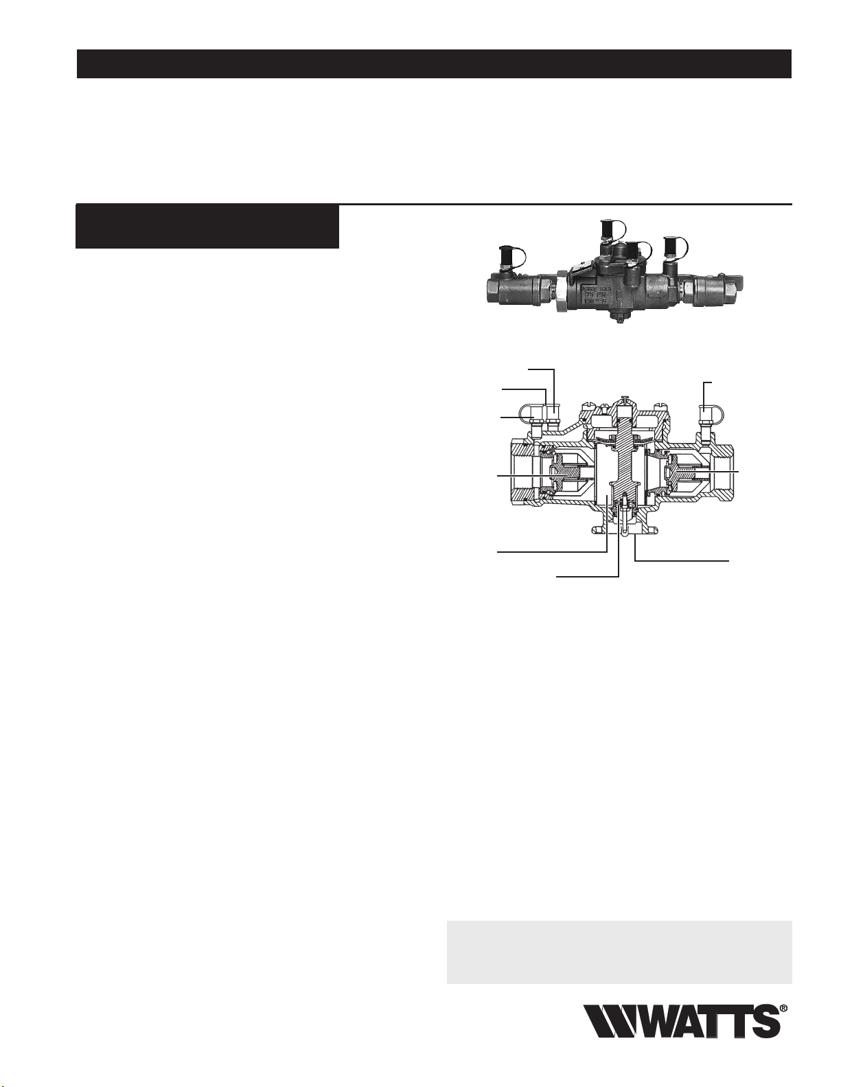
SS009QT
Test Cock No. 3
EZ-TC-SS
Test Cocks
Test Cock
No. 2
First Check
Module
Assembly
R.P. Zone
Relief Valve Assembly
Test Cock No. 4
Second
Check
Module
Assembly
Water Outlet
Specifications
A reduced pressure zone assembly shall be installed at each noted
potential health hazard location to prevent backflow due to backsiphonage and/or backpressure. The assembly shall consist of an
internal pressure differential relief valve located in a zone between
two independently operating positive seating check modules with
captured springs and silicone seat discs. Seats and seat discs shall
be replaceable in both check modules and the relief valve, without
the use of special tools. There shall be no threads or screws, in the
waterway, exposed to line fluids. Service of all internal components
shall be through a single access cover secured with stainless steel
bolts. The assembly shall include two resilient seated isolation
valves, four top mounted vandal resistant test cocks with dust covers, a protective stainless steel wye strainer with a 20 mesh screen
and an air gap fitting. The assembly shall consist of an investment
cast 316 Stainless Steel body and cover with Series 300 Stainless
Steel test cocks, 316 Stainless Steel Ball Valve Shutoffs with PTFE
Seat blowout proof 304 Stainless Steel Stems, and 304 Stainless
Steel Tee Handles. The assembly shall meet the requirements of
ASSE Standard 1013, AWWA Standard C511. Assembly shall be a
Watts Regulator Company Series SS009QT.
Now Available
WattsBox Insulated Enclosures.
For more information, send for literature ES-WB.
Watts product specifications in U.S. customary units and metric are approximate and are provided for reference only. For precise measurements,
please contact Watts Technical Service. Watts reserves the right to change or modify product design, construction, specifications, or materials without prior notice and without incurring any obligation to make such changes and modifications on Watts products previously or subsequently sold.
Page 2
Available Models
Suffix:
QT – quarter-turn ball valves
S – stainless steel strainer
Note: The installation of a drain line is recommended. When
installing a drain line, an air gap is necessary (see ES-AG/EL/TC).
Materials
Body: 316 stainless steel
Disc and Relief Valve: Silicone rubber
Check Seats: Replaceable polymer
Relief Valve Seat: Stainless steel
Cover Bolts: Stainless steel
Pressure — Temperature
Temperature Range: 33°F – 180°F (0.5°C – 82°C) continuous
Maximum Working Pressure: 175psi (12.1 bar)
Standards
USC Manual 9th Edition
AWWA C511-92
1013
B64.4
61
Approvals
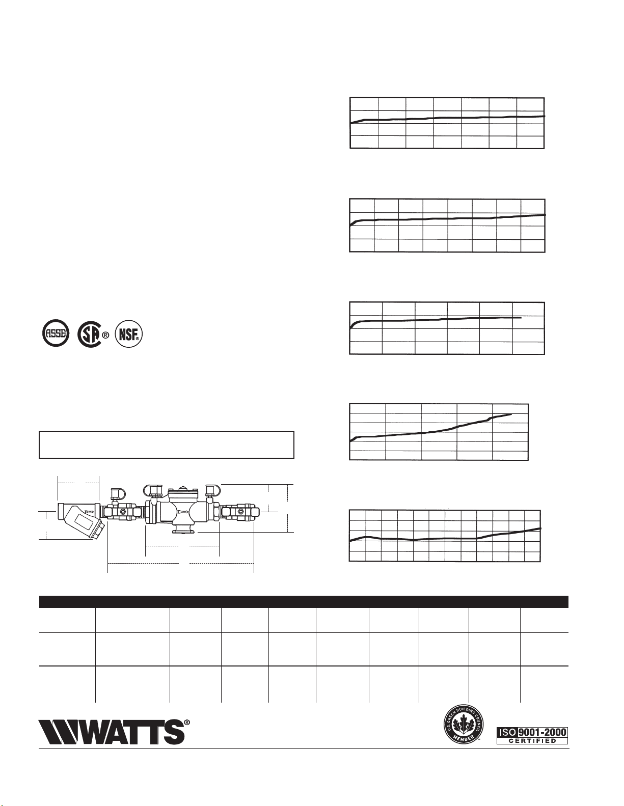
Capacity
Performance as established by an independent testing laboratory.
*Typical maximum system flow rate (7.5 feet/sec.)
kPa psi
138 20
103 15
69 10
34 5
00
0 0.2 0.4 0.6 0.8 1 1.2 1.4 gpm
0 .76 1.5 2.3 3 3.8 4.6 5.3 lpm
kPa psi
138 20
103 15
69 10
34 5
00
0 0.5 1 1.5 2 2.5 3 3.5 4 gpm
0 1.9 3.8 5.7 7.6 9.5 11.4 13.3 15.2 lpm
kPa psi
138 20
103 15
69 10
34 5
00
0 2 4 6 8 10 12 gpm
0 7.6 15 23 30 38 46 lpm
1
⁄4" (8mm)
3
⁄8" (10mm)
1
⁄2" (15mm)
ASSE, AWWA, USC
1
CSA –
Dimensions — Weight
⁄2" and 3⁄4" horizontal
IMPORTANT: INQUIRE WITH GOVERNING AUTHORITIES
FOR LOCAL INSTALLATION REQUIREMENTS
M
C
B
N
L
A
MODEL SIZE (DN) DIMENSIONS (approx.) WEIGHT
A B C L M N Width
in. mm in. mm in. mm in. mm in. mm in. mm in. mm in. mm lbs. kgs.
kPa psi
207 30
172 25
138 20
103 15
69 10
34 5
00
0 1020 3040 50gpm
0 38 75 114 152 190 lpm
kPa psi
172 25
138 20
103 15
69 10
34 5
00
0 5 10 15 20 25 30 35 40 45 50 55 60 gpm
0 1938577695
3
⁄4" (20mm)
1" (25mm)
114 133 152 171 190 209 228
lpm
SS009M3QT1⁄4,3⁄8,1⁄2 8,10,15 10 250 45⁄8 117 33⁄8 86 51⁄2 140––––51274.50 2.0
SS009M3QT
SS009QT 1 25 16
3
⁄4 20 103⁄4 273 5 127 31⁄2 89 63⁄4 171––––61⁄4 159 5.75 2.6
3
⁄4 425 51⁄2 140 3 76 91⁄2 241––––81⁄4 210 12.25 5.6
SS009M3QT-S1⁄4,3⁄8,1⁄2 8,10,15 10 250 6 150 33⁄8 86 51⁄2 140 313⁄16 97 25⁄8 67 5 127 7.25 3.3
SS009M3QT-S
SS009QT-S 1 25 16
3
⁄4 20 103⁄4 273 61⁄4 159 31⁄2 89 63⁄4 171 43⁄8 111 33⁄16 81 61⁄4 159 9.25 4.2
3
⁄4 425 73⁄4 197 3 76 91⁄2 241 53⁄16 132 33⁄4 95 81⁄4 210 17.00 7.7
A Watts Water Technologies Company
Canada: 5435 North Service Rd., Burlington, ONT. L7L 5H7; www.wattscanada.ca
ES-SS009 0940 © 2009 Watts
USA: 815 Chestnut St., No. Andover, MA 01845-6098; www.watts.com
 Loading...