

Page 1

Installation, Maintenance, & Repair
Series 007 and LF007
Double Check Valve Assemblies
Sizes: 1⁄2" – 3" (15 - 80mm)
!
WARNING
3
Read this Manual BEFORE using this equipment.
Failure to read and follow all safety and use information
can result in death, serious personal injury, property
damage, or damage to the equipment.
Keep this Manual for future reference.
Installation Instructions
⁄4" 007M3QT
RP/IS-007
Local building or plumbing codes may require modifications to the
information provided. You are required to consult the local building
and plumbing codes prior to installation. If this information is not
consistent with local building or plumbing codes, the local codes
should be followed.
Need for Periodic Inspection/Maintenance: This product must
be tested periodically in compliance with local codes, but at least
once per year or more as service conditions warrant. Corrosive
water conditions, and/or unauthorized adjustments or repair could
render the product ineffective for the service intended. Regular
checking and cleaning of the product’s internal components helps
assure maximum life and proper product function.
NOTICE
For Australia and New Zealand, line strainers should be installed
between the upstream shutoff valve and the inlet of the backflow
preventer.
Watts product specifications in U.S. customary units and metric
are approximate and are provided for reference only. For precise
measurements, please contact Watts Technical Service. Watts
reserves the right to change or modify product design, construction, specifications, or materials without prior notice and without
incurring any obligation to make such changes and modifications
on Watts products previously or subsequently sold.
Testing
For field testing procedure, refer to Watts installation sheets
IS-TK-DP/DL, IS-TK-9A, IS-TK-99E and IS-TK-99D found on
www.watts.com.
For other repair kits and service parts, refer to our Backflow
Prevention Products Repair Kits & Service Parts price list PL-RPBPD found on www.watts.com.
For technical assistance, contact your local Watts representative.
Series 007 and LF007
1
⁄2" - 2" (15 - 50mm)
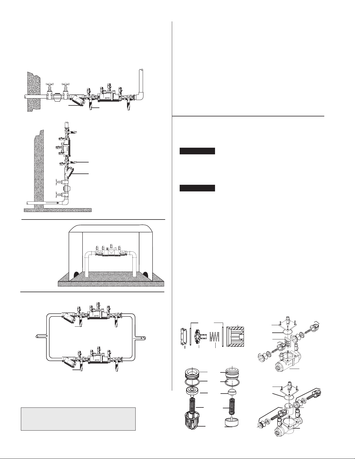
Indoors - Figure 1
Check local codes for installation requirements. Pipe lines should
be thoroughly flushed to remove foreign material before installing
the unit. A strainer should be installed as shown, ahead of backflow
preventer to prevent disc from unnecessary fouling. Install valve
inline with arrow on valve body pointing in the direction of flow.
For indoor installations, it is important that the valve be easily accessible to facilitate testing and servicing. Do not install in a concealed
location.
!
CAUTION
Do not install with strainer when backflow preventer is used on
seldom-used water lines which are called upon during emergencies, such as fire sprinkler lines, etc.
It is important that Series 007 and LF007 be tested periodically in
compliance with local codes, but at least once a year or more often
depending upon system conditions. Regular inspection, testing and
cleaning assures maximum life and proper product function.
NOTICE
Fire Protection System Installations
The National Fire Protection Agency (NFPA) Guidelines require a
confirming flow test to be conducted whenever a “main line” valve
such as the shutoff valves or a backflow assembly have been operated. Certified testers of backflow assemblies must conduct this
test. The trim valves of the confirming flow test. When the test is
completed, the trim valves must be returned to a fully open position.
Meter Box Installation
Page 2
Installation Instructions
Series 007 and LF007
1
⁄2" - 2" (15 - 50mm)
Figure 1
Strainer
007QT-S / LF007QT-S
First Shutoff
007QT-S/LF007QT-S
Vertical flow-up installation
Figure 2
WattsBox Insulated
Enclosure
Available in Aluminum
or Fiberglass.
For more information,
send for ES-WB.
Figure 3
First
Shutoff Valve
Valve
Strainer
Parallel - Figure 3
Two or more Series 007 and LF007 smaller size valves may be
piped in parallel (where approved) to serve a larger supply pipe
main. This type of installation is employed whenever it is vital to
maintain a continuous supply of water/where interruptions for testing and servicing would be unacceptable. It also has the advantage
of providing increased capacity where needed beyond that provided
by a single valve and permits testing or servicing of an individual
valve without shutting down the
complete line.
For two valve installations the total capacity of the devices should
equal or exceed that required by the system.
The quantity of valves used in parallel should be determined by
the engineers judgement based on the operating conditions of a
specific installation.
Service and Maintenance
Servicing the First and Second Check Valves
NOTICE
Before servicing, ensure supply water is turned off or shutoff valves
are in the closed position.
1. Remove the cover, then remove the retainer from the body
valve. The check valve modules can now be removed from the
valve by hand or with a screwdriver.
NOTICE
For Series 007 and LF007 sizes 1⁄2" - 2" (15-50mm), the seats and
springs of the first and second check modules are not interchangeable. The heavier spring and smaller diameter seat belong with the
first check module. Series 007M1 sizes
Series 007M2
3
⁄4" (20mm) have interchangeable seats and springs.
2. The check seats are attached to the cage with a bayonet type locking arrangement. Holding the cage in one hand, push the seat inward and rotate clockwise against the cage. For
007M2/LF007M2 and LF007 pull apart seat and cage. The seat,
cage, spring and disc assembly are now individual components.
3. The disc assembly may now be cleaned and reassembled or,
depending on its condition, it may be discarded and replace with
a new assembly from the repair kit. O-rings should be cleaned or
replaced as necessary.
4. Reassemble the check valve module in the reverse order. Check
modules are installed in the valve body with the seats facing the
valve inlet. The modules must be securely in place before the
retainer can be replaced. On the
retainer may have to be tilted slightly into place. Replace cover.
3
⁄4" - 1" (20-25mm) and
3
⁄4" (20mm) Series
3
⁄4" - 1" (20-25mm)size, this
First
Shutoff Valve
First Shutoff Valve
007QT-S / LF007QT-S
For repair kits and parts, refer to our Backflow
Prevention Products Repair Kits & Service Parts
price list PL-RP-BPD found on www.watts.com.
2
Seat
O-rings
Disc
Spring
Seat
Seat
O-ring
Disc
Assembly
Spring
Check
Cage
Check
Cage
Cover
Cover
O-ring
Retainer
First Check
Cover
Cover
O-ring
First Check
Second Check
Body
Second Check
Retainer
Body
Page 3

Installation Instructions
Series 007 and LF007
21⁄2" and 3"
Indoors - Figure 4
Series 007 may be installed in either a vertical or horizontal position. Pipe lines should be thoroughly flushed to remove foreign material before installing the unit. A strainer should be installed
as shown, ahead of backflow preventer to prevent disc from
unnecessary fouling. Install valve inline with arrow on valve body
pointing in the direction of flow.
For indoor installations, it is important that the valve be easily
accessible to facilitate testing and servicing. Do not install in a concealed location.
!
CAUTION
Do not install with strainer when backflow preventer is used on seldom-used water lines which are called upon during emergencies,
such as fire sprinkler lines, etc.
It is important that Series 007 and LF007 be tested periodically in
compliance with local codes, but at least once a year or more often
depending upon system conditions.
NOTICE
Fire Protection System Installations
The National Fire Protection Agency (NFPA) Guidelines require a
confirming flow test to be conducted whenever a “main line” valve
such as the shutoff valves or a backflow assembly have been operated. Certified testers of backflow assemblies must conduct this
test. The trim valves of the detector meter bypass line, on assemblies so equipped, should be shutoff during the confirming flow
test. When the test is completed, the trim valves must be returned
to a fully open position.
Figure 4
Meter
Strainer
Series 77F-DI-FDA-125
21⁄2", 3" 007 / LF007
Outside Building Above Ground -
Figure 5
In an area where freezing conditions do not occur, Series 007 and
LF007 can be installed outside of a building. The most satisfactory
installation is above ground and should be installed in this manner
whenever possible. In an area where freezing conditions can occur,
Series 007 and LF007 should be installed above ground in an insulated enclosure.
Annual inspection of all water system safety and control valves is
required and necessary. Regular inspection, testing and cleaning
assures maximum life and proper product function.
Parallel - Figure 6
Consult Local codes for Approval
Two or more Series 007 and LF007 smaller size valves may be
piped in parallel (where approved) to serve a larger supply pipe
main. This type of installation is employed whenever it is vital to
maintain a continuous supply of water/where interruptions for testing and servicing would be unacceptable. It also has the advantage
of providing increase capacity where needed beyond that provided
by a single valve and permits testing or servicing of an individual
valve without shutting down the complete line. For two valve installations the total capacity should equal or exceed that required by
the system.
The quantity of valves used in parallel should be determined by the
engineer's judgement based on the operating conditions of a specific installation. (See F-FC regarding flow curves)
NOTICE
The flange gasket bolts for the gate valves should be retightened
during installation as the bolts may have loosened due to storage
and shipping.
Figure 5
Figure 6
WattsBox Insulated Enclosures
Available in Aluminum or Fiberglass.
For more information, send for ES-WB.
Strainer Series 77F-DI-FDA-125
1
2
⁄2", 3" 007 / LF007
3
Page 4

Servicing First and Second Check Valves
Series 007 and LF007
21⁄2" and 3"
1. Remove cover bolts and cover.
2. Remove the retainer from the body bore. The check valve
modules can now be removed from the valve by hand or with a
screwdriver.
3. The check seats are attached to the cage with a bayonet type
locking arrangement. Holding the cage in one hand, push the
seat inward and rotate counterclock-wise against the cage. The
seat, spring cage, spring and disc assembly are now individual
components.
4. The disc assembly may now be cleaned and reassembled or
depending on its condition, may be discarded and replaced with
a new assembly from the repair kit. O-rings should be cleaned or
replaced as necessary. For more information, refer to repair parts
price list PL-RP-BPD.
5. Reassemble the Check valve modules. Check modules are
installed in the valve body with the seats facing the valve inlet.
The modules must be securely in place before the retainer can
be replaced.
No special tools required to service Series 007 and LF007.
Seat
Seat
O-ring
Cover
Cover O-ring
Retainer
First Check
Disc
Assembly
Check Assemblies
Spring Retainer
Second Check
Caps/
Seat
Body
Troubleshooting Guide — Series 007 and LF007
Symptom Cause Solution
1. Check valve fails to hold
1.0 PSID minimum
2. Chatter during flow
conditions
3. Low flows passing through
mainline valve
For repair kits and parts, refer to our Backflow
Prevention Products Repair Kits & Service Parts
price list PL-RP-BPD found on www.watts.com.
Limited Warranty: Watts Regulator Co. (the “Company”) warrants each product to be free from defects in material and workmanship under normal usage for a period of one year from the date of
original shipment. In the event of such defects within the warranty period, the Company will, at its option, replace or recondition the product without charge.
THE WARRANTY SET FORTH HEREIN IS GIVEN EXPRESSLY AND IS THE ONLY WARRANTY GIVEN BY THE COMPANY WITH RESPECT TO THE PRODUCT. THE COMPANY MAKES NO OTHER
WARRANTIES, EXPRESS OR IMPLIED. THE COMPANY HEREBY SPECIFICALLY DISCLAIMS ALL OTHER WARRANTIES, EXPRESS OR IMPLIED, INCLUDING BUT NOT LIMITED TO THE IMPLIED
WARRANTIES OF MERCHANTABILITY AND FITNESS FOR A PARTICULAR PURPOSE.
The remedy described in the first paragraph of this warranty shall constitute the sole and exclusive remedy for breach of warranty, and the Company shall not be responsible for any incidental,
special or consequential damages, including without limitation, lost profits or the cost of repairing or replacing other property which is damaged if this product does not work properly, other costs
resulting from labor charges, delays, vandalism, negligence, fouling caused by foreign material, damage from adverse water conditions, chemical, or any other circumstances over which the Company
has no control. This warranty shall be invalidated by any abuse, misuse, misapplication, improper installation or improper maintenance or alteration of the product.
Some States do not allow limitations on how long an implied warranty lasts, and some States do not allow the exclusion or limitation of incidental or consequential damages. Therefore the above
limitations may not apply to you. This Limited Warranty gives you specific legal rights, and you may have other rights that vary from State to State. You should consult applicable state laws to
determine your rights. SO FAR AS IS CONSISTENT WITH APPLICABLE STATE LAW, ANY IMPLIED WARRANTIES THAT MAY NOT BE DISCLAIMED, INCLUDING THE IMPLIED WARRANTIES OF
MERCHANTABILITY AND FITNESS FOR A PARTICULAR PURPOSE, ARE LIMITED IN DURATION TO ONE YEAR FROM THE DATE OF ORIGINAL SHIPMENT.
a. Debris on check disc sealing surface Disassemble and clean
b. Leaking gate valve Disassemble and clean or repair
c. Damaged seat disc or seat o-ring Disassemble and replace
d. Damaged guide holding check open Disassemble and clean or replace
e. Weak or broken spring Disassemble and replace spring
a. Worn, damaged or defective guide Disassemble and repair or replace guide
a. Mainline check fouled Disassemble and clean
b. Meter strainer plugged Disassemble and clean
c. Damaged mainline seat disc or seat Disassemble and replace
d. Broken mainline spring Disassemble and replace
WARNING: This product contains chemicals known to the
State of California to cause cancer and birth defects or
other reproductive harm.
For more information: www.watts.com/prop65
A Watts Water Technologies Company
RP-IS-007 1319 EDP# 1915216 © 2013 Watts
USA: Tel: (978) 688-1811 • Fax: (978) 794-1848 • www.watts.com
Canada: Tel: (905) 332-4090 • Fax: (905) 332-7068 • www.wattscanada.ca
 Loading...