

Page 1
Basic Temperature and Limit Controllers
Basic Temperature
and Limit Controllers
Provide Economical
Solution for a Wide
Range of Applications
SPECIFICATION SHEET
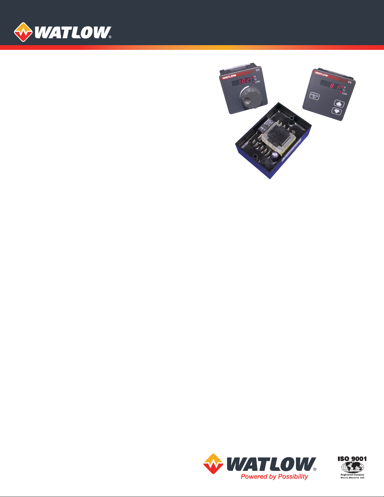
The basic and limit microprocessor-based controllers from
Watlow® provide an economical solution for applications
requiring simple on-o control. These controllers and limits
are available in a broad range of packaging options, allowing
users to select the best version for their individual application.
The controllers and limits are available with or without an
operator interface and can be ordered in a 1/8 DIN square panel
mount, DIN-rail mount or open-board design congurations.
The basic and limit design provides significant improvements
in the performance, repeatability and accuracy offered by
analog basic temperature and limit controllers.
The variable options for the SERIES CV (controller) and
SERIES LV (limit) include an operator interface for viewing
and selecting the set point. A red, four-character, seven
segment LED displays the set point to show the process
option. The set point selection is made with a continuous
turn rotary encoder, or with discrete up/down cursor keys.
Operating range temperature values are customer definable
in the product configuration part number.
The fixed options for the SERIES CF (controller) and
SERIES LF (limit) offer fixed set points and are supplied
without an operator interface. Operating set point
temperature values are customer definable in the product
configuration part number. The SERIES TM temperature
indicator is available as an additional order option.
These basic and limit controllers are UL® recognized and
include CE approvals. The limit controllers are FM approved
with special UL® approval for the open-board potted versions.
CV and LV panel mount controllers ordered with discrete
up/down cursor keys include NEMA 4X/IP65 seal protection.
Watlow’s basic temperature and limit controllers include
industry leading service and support and are backed by a
three-year warranty.
Features and Benefits
Fixed or adjustable set points
• Provide tamper-proof operation
• Offer control flexibility
Four character LED display
• Improves set point selection accuracy
Multiple mounting options
• Minimize installation time
Heat or cool operation
• Provides application flexibility
High or low limit with auto or manual reset
• Provides application flexibility
Fahrenheit or Celsius operation with indication
• Offers application flexibility
Sensor break protection
• Provides positive system shutdown
Agency approvals
• Meet certification requirements/compliance
Microprocessor-based technology
• Ensures accurate, repeatable control
Typical Applications
• Food preparation
• Industrial machinery
• Packaging
• Plastics processing
Page 2

Specifications
On-Off Controller
• Microprocessor based, on-off control mode
• Nominal switching hysteresis, typically 3°F (1.7°C)
• Input filter time: 1 second
Limit Controller
• Microprocessor based, limit controller
• Nominal switching hysteresis, typically 3°F (1.7°C)
• High or low limit, factory selectable
• Latching output requires manual reset upon over or under
temperature condition
• Manual or automatic reset on power loss, factory selectable
• Internal front panel or external customer supplied
momentary reset switch
• Input filter time: 1 second
Operator Interface
•
Four digit, seven segment LED displays, 0.28 in. (7 mm) high
• °F or °C indicator LED
• Load/Alarm indicator LED
• Continuous turn, velocity sensitive rotary encoder for set
point adjustment
• Front panel key on push for set point or push for show
process options (on-off controller only)
• Front panel SET/RESET key on variable set point models
(limit controller only)
• No operator interface on fixed set point models
Standard Conditions For Specications
• Rated line voltage, 50 to 60Hz, 0 to 90% RH
non-condensing, 15-minute warm-up
• Calibration ambient range: 77°F (25°C) ±3°C
Sensor Input
Thermocouple
• Grounded or ungrounded
• Type E, J, K, T thermocouple types
• >10 MΩ input impedance
• 250 nV input referenced error per 1Ω source resistance
RTD
• 2-wire platinum, 100Ω
• DIN curve (0.00385 curve)
• 125 µA nominal RTD excitation current
Input Accuracy Span Range
Type E: -328 to 1470°F or -200 to 800°C
Type J: 32 to 1382°F or 0 to 750°C
Type K: -328 to 2282°F or -200 to 1250°C
Type T: -328 to 662°F or -200 to 350°C
RTD (DIN) -328 to 1472°F or -200 to 800°C
Thermocouple Input
• Calibration accuracy: ±1% of input accuracy span, ±1°
at standard conditions and actual calibration ambient
Exception: Type T, ±2.4% of input accuracy span for
-200 to 0°C (-328 to 32°F)
•
Temperature stability: ±0.3° per degree change in ambient
RTD Input
• Calibration accuracy ±1% of input accuracy span ±1° at
standard conditions and actual calibration ambient
• Temperature stability: ±0.2° per degree change in ambient
Allowable Operating Ranges
Type E: -328 to 1470°F or -200 to 800°C
Type J: -346 to 1900°F or -210 to 1038°C
Type K: -454 to 2500°F or -270 to 1370°C
Type T: -454 to 750°F or -270 to 400°C
RTD (DIN) -328 to 1472°F or -200 to 800°C
Output Types
Switched dc (non-isolated, on-o controller only)
• Supply voltage max.: 24VDC into an infinite load
• Supply voltage min.: 5VDC at 10mA
• Min. load impedance: 500Ω
Electromechanical Relay, Form C
• Min. load current: 100mA
• 8A @ 240VAC or 30VDC max., resistive
• 250VA pilot duty, 120/240VAC max., inductive
• Use RC suppression for inductive loads
• Electrical life 100,000 cycles at rated current
External Reset Switch (limit controller only)
• Momentary, dry contact closure
Agency Approvals
• CE a, W.E.E.E., RoHS EU Directive (2002-95-EC)
Agency Approvals (on-o controller only)
• UL® 873 recognized temperature controller and indicator,
File # E43684
• UL® 197 reviewed for use in foodservice appliances
• ANSI Z21.23 gas appliance thermostat approval
• Temperature control and indicator CSA 22.2 No. 24,
File # 30586
• NEMA 4X/IP65 (SERIES CV and LV panel mount
controllers with up/down cursor keys)
Agency Approvals (limit controller only)
SERIES LF (potted version only)
• UL® 991 recognized temperature limit for foodservice
industry
SERIES LV and SERIES LF (including potted version)
• UL® 873 recognized temperature regulator, File # E43684
• UL® 197 reviewed for use in foodservice appliances
• ANSI Z21.23 gas appliance thermostat approval
• CSA C22.2#24 approved temperature control,
File # 30586
• FM Class 3545 temperature limit switches, File # 3017239
Terminals
• 0.25 in. (6.3 mm) quick connect, push on terminal or
removable screw style terminal block
Power
• 24VAC +10%; -15%; 50/60Hz, ±5%
• 100 to 120VAC +10%; -15%; 50/60Hz, ±5%
• 200 to 240VAC +10%; -15%; 50/60Hz, ±5%
• 10VA max. power consumption
•
Data retention upon power failure via nonvolatile memory
Operating Environment
• 32 to 158°F (0 to 70°C)
• 0 to 90% RH, non-condensing
• Storage temperature: -40 to 185°F (-40 to 85°C)
Dimensions
• DIN-rail model can be DIN-rail or chassis mount
DIN-rail spec DIN 50022, 1.38 in. x 0.30 in. (35 mm x 7.5 mm)
Style Width Height Depth
Open Board
Potted
DIN-rail
Square 1/8
DIN Panel
a
See declaration of comformity.
2.43 in.
(61.7 mm)
2.76 in.
(70.1 mm)
3.08 in.
(78.1 mm)
2.85 in.
(72.4 mm)
2.43 in.
(61.7 mm)
4.05 in.
(102.9 mm)
4.42 in.
(112.3 mm)
2.85 in.
(72.4 mm)
1.78 in.
(45.1 mm)
1.84 in.
(46.6 mm)
3.57 in.
(90.7 mm)
Behind panel
2.04 in.
(51.7 mm)
Page 3

Ordering Information
Part Number
Indicator only, 4 character, 7 segment display
① ②
TM
③
Power
Supply④Package
⑤
Sensor
Type and
Scale
⑥ ⑦ ⑧ ⑨ ⑩ ⑪ ⑫ ⑬ ⑭
AAAAAAAAA
⑮
③
B = 120VAC
D = 230 to 240VAC
F = 24VAC
④
Panel mount, 1/8 DIN square - spade terminals
1 =
DIN-rail mount - spade terminals
2 =
Panel mount, 1/8 DIN square - screw terminals
5 =
DIN-rail mount - screw terminals
6 =
NEMA 4X panel mount, (spade terminals)
A =
NEMA 4X panel mount, (screw terminals)
C =
Power Supply
Package
Ordering Information
Part Number
Limit control with 8A relay output. Fixed set point, no user interface
① ②
LF
③
C = 120VAC
E = 230 to 240VAC
G = 24VAC
④
1 =
2 =
3 =
4 =
5 =
6 =
7 =
⑤
H =
J =
K =
L =
M =
N =
P =
R =
S =
T =
③
Power
Supply④Package
Panel mount, 1/8 DIN square - spade terminals
DIN-rail mount - spade terminals
Open, non potted - spade terminals
Potted case - spade terminals
Panel mount, 1/8 DIN square - screw terminals
DIN-rail mount - screw terminals
Open, non potted - screw terminals
Sensor Type and Scale
T/C Type J °F (-346 to 1900°F)
T/C Type J °C (-210 to 1038°C)
T/C Type K °F (-454 to 2500°F)
T/C Type K °C (-270 to 1370°C)
T/C Type T °F (-454 to 750°F)
T/C Type T °C (-270 to 400°C)
RTD °F (-328 to 1472°F)
RTD °C (-200 to 800°C)
T/C Type E °F (-328 to 1470°F)
T/C Type E °C (-200 to 800°C)
⑤
Sensor
Type and
Scale
Power Supply
Package
⑥
Limit
Type
⑦ ⑧ ⑨ ⑩
Fixed Set Point
Temp. Value
⑤
T/C Type J °F (-346 to 1900°F)
H =
T/C Type J °C (-210 to 1038°C)
J =
T/C Type K °F (-454 to 2500°F)
K =
T/C Type K °C (-270 to 1370°C)
L =
T/C Type T °F (-454 to 750°F)
M =
T/C Type T °C (-270 to 400°C)
N =
RTD °F (-328 to 1472°F)
P =
RTD °C (-200 to 800°C)
R =
T/C Type E °F (-328 to 1470°F)
S =
T/C Type E °C (-200 to 800°C)
T =
⑮
A =
Standard with Watlow logo
1 =
Standard without Watlow logo
⑪ ⑫ ⑬ ⑭
Overlay/
Custom
Options
Sensor Type and Scale
Overlay/Customs Options
⑮
AAAA
⑥
U = High limit manual reset
W = High limit auto reset
Y = Low limit manual reset
Z = Low limit auto reset
⑦
⑧⑨ ⑩
Note: An A (-) used in the left most digit of the xed set point
indicates a negative temperature value.
⑮
A =
Standard with Watlow logo
1 =
Standard without Watlow logo
Fixed Set Point Temperature Value
Limit Type
Overlay/Customs Options
Page 4

Ordering Information
Part Number
Limit control with 8A relay output. Rotary set point adjustment, 4 character, 7 segment display, reset switch
① ②
LV
③
Power
Supply④Package
⑤
Sensor
Type and
Scale
⑥
Limit
Type
⑦ ⑧ ⑨ ⑩
Low Set Point
Operating
Range Value
⑪ ⑫ ⑬ ⑭
High Set Point
Operating
Range Value
⑮
Overlay/
Custom
Options
③
C = 120VAC
E = 230 to 240VAC
G = 24VAC
④
Panel mount, 1/8 DIN square - spade terminals
1 =
DIN-rail mount - spade terminals
2 =
Panel mount, 1/8 DIN square - screw terminals
5 =
DIN-rail mount - screw terminals
6 =
NEMA 4X panel mount, tactile keys (spade terminals)
A =
DIN-rail mount, tactile keys (spade terminals)
B =
NEMA 4X panel mount, tactile keys (screw terminals)
C =
DIN-rail mount, tactile keys (screw terminals)
D =
⑤
T/C Type J °F (-346 to 1900°F)
H =
T/C Type J °C (-210 to 1038°C)
J =
T/C Type K °F (-454 to 2500°F)
K =
T/C Type K °C (-270 to 1370°C)
L =
T/C Type T °F (-454 to 750°F)
M =
T/C Type T °C (-270 to 400°C)
N =
RTD °F (-328 to 1472°F)
P =
RTD °C (-200 to 800°C)
R =
T/C Type E °F (-328 to 1470°F)
S =
T/C Type E °C (-200 to 800°C)
T =
Power Supply
Package
Sensor Type and Scale
⑥
U = High limit manual reset
W = High limit auto reset
Y = Low limit manual reset
Z = Low limit auto reset
⑧⑨ ⑩
⑦
Note: An A (-) used in the left most digit of the xed set point
indicates a negative temperature value.
⑪
⑫⑬⑭
Note: An A (-) used in the left most digit of the xed set point
indicates a negative temperature value.
⑮
A =
1 =
Low Limit Set Point Operating Range Value
High Set Operating Range Value
Standard with Watlow logo
Standard without Watlow logo
Limit Type
Overlay/Customs Options
Ordering Information
Part Number
On-o controller, xed set point, no user interface
① ②
CF
③
B = 120VAC, switched dc output
C = 120VAC, 8A relay output
D = 230 to 240VAC, switched dc output
E = 230 to 240VAC, 8A relay output
F = 24VAC, switched dc output
G = 24VAC, 8A relay output
④
1 =
2 =
3 =
4 =
5 =
6 =
7 =
③
Power
Supply④Package
Panel mount, 1/8 DIN square - spade terminals
DIN-rail mount - spade terminals
Open board, non potted - spade terminals
Potted case - spade terminals
Panel mount, 1/8 DIN square - screw terminals
DIN-rail mount - screw terminals
Open board, non potted - screw terminals
⑤
Sensor
Type and
Scale
Power Supply
Package
Control
Type
⑥
⑦ ⑧ ⑨ ⑩
Fixed Set Point
Temp. Value
⑪ ⑫ ⑬ ⑭
⑮
Overlay/
Custom
Options
AAAA
⑤
T/C Type J °F (-346 to 1900°F)
H =
T/C Type J °C (-210 to 1038°C)
J =
T/C Type K °F (-454 to 2500°F)
K =
T/C Type K °C (-270 to 1370°C)
L =
T/C Type T °F (-454 to 750°F)
M =
T/C Type T °C (-270 to 400°C)
N =
RTD °F (-328 to 1472°F)
P =
RTD °C (-200 to 800°C)
R =
T/C Type E °F (-328 to 1470°F)
S =
T/C Type E °C (-200 to 800°C)
T =
⑥
H = Heat
C = Cool
⑦
⑧⑨ ⑩
Note: An A (-) is used in the left most digit of the set point
operating ranges to indicate a negative temperature value.Z
⑮
A =
Standard with Watlow logo
1 =
Standard without Watlow logo
Sensor Type and Scale
Control Type
Fixed Set Point Temperature Value
Overlay/Customs Options
Page 5

Ordering Information
Part Number
On-o controller, rotary set point adjustment, 4 character, 7 segment display
① ②
CV
③
B = 120VAC, switched dc output
C = 120VAC, 8A relay output
D = 230 to 240VAC, switched dc output
E = 230 to 240VAC, 8A relay output
F = 24VAC, switched dc output
G = 24VAC, 8A relay output
④
1 =
2 =
5 =
6 =
A =
B =
C =
D =
⑤
H =
J =
K =
L =
M =
N =
P =
R =
S =
T =
③
Power
Supply④Package
⑤
Sensor
Type and
Scale
⑥
Control
Type
⑦ ⑧ ⑨ ⑩
Low Set Point
Operating
Range Value
Power Supply
Package
Panel mount, 1/8 DIN square - spade terminals
DIN-rail mount - spade terminals
Panel mount, 1/8 DIN square - screw terminals
DIN-rail mount - screw terminals
NEMA 4X panel mount, tactile keys (spade terminals)
DIN-rail mount, tactile keys (spade terminals)
NEMA 4X panel mount, tactile keys (screw terminals)
DIN-rail mount, tactile keys (screw terminals)
Sensor Type and Scale
T/C Type J °F (-346 to 1900°F)
T/C Type J °C (-210 to 1038°C)
T/C Type K °F (-454 to 2500°F)
T/C Type K °C (-270 to 1370°C)
T/C Type T °F (-454 to 750°F)
T/C Type T °C (-270 to 400°C)
RTD °F (-328 to 1472°F)
RTD °C (-200 to 800°C)
T/C Type E °F (-328 to 1470°F)
T/C Type E °C (-200 to 800°C)
⑪ ⑫ ⑬ ⑭
High Set Point
Operating
Range Value
⑥
⑮
Overlay/
Custom
Options
Control Type
H = Heat
C = Cool
⑦
⑧⑨⑩
Low Set Point Operating Range Value
Note: An A (-) is used in the left most digit of the set point operating
ranges to indicate a negative temperature value.
⑪
⑫⑬ ⑭
High Set Operating Range Value
Note: An A (-) is used in the left most digit of the set point operating
ranges to indicate a negative temperature value.
⑮
A =
Standard with Watlow logo
B =
Push to show process with Watlow logo
C =
Push to adjust set point with Watlow logo
D =
Show process push to adjust set point with Watlow logo
1 =
Standard without Watlow logo
2 =
Push to show process without Watlow logo
3 =
Push to adjust set point without Watlow logo
4 =
Show process push to adjust set point without Watlow logo
Overlay/Customs Options
Powered by Possibility
To be automatically connected to the nearest
North American Technical Sales Oce:
1-800-WATLOW2 • www.watlow.com
inquiry@watlow.com
©2016 Watlow Electric Manufacturing Company all rights reserved.
International Technical Sales Offices:
Austria +43 6244 20129 0
Australia +61 3 9335 6449
China +86 21 3532 8532
France +33 1 41 32 79 70
Watlow® is a registered trademark of Watlow Electric Manufacturing Company.
UL® is a registered trademark of the Underwriter’s Laboratories, Inc.
Germany +49 7253 9400 0
India +91 40 6661 2700
Italy +39 02 4588841
Japan +81 3 3518 6630
Korea +82 2 2169 2600
Mexico +52 442 256 2200
Singapore +65 6773 9488
Spain +34 91 675 1292
Taiwan +886 7 288 5168
UK +44 115 964 0777
WIN-BLTC-0716
 Loading...