

Page 1

CPC400 Series
User’s Guide
Watlow Controls
1241 Bundy Blvd.
Winona, MN 55987
Repairs and Returns:
334 Westridge Drive
Watsonville, CA 95076
Customer Service:
Phone.....1-800-414-4299
Fax.........1-800-445-8992
Technical Support:
Phone.....(507) 494-5656
Fax.........(507) 452-4507
Email ......wintechsupport@watlow.com
Part No. 0600-2900-2000 Rev. 2.2
August 2005
Page 2

Copyright © 2005, Watlow Anafaze, Incorporated
Information in this manual is subject to change without notice. No part of this publication may be reproduced, stored in a retrieval system, or transmitted in any form
without written permission from Watlow Anafaze.
Anafaze is a registered trademark, and LogicPro is a trademark, of Watlow Electric
Manufacturing Company. Modbus is a trademark of Schneider Automation Incorporated. Windows is a registered trademark of Microsoft Corporation in the United
States and/or other countries. UL is a registered trademark of Underwriters Laboratories, Inc. All other trademarks are the property of their respective owners.
Warranty
Watlow Anafaze, Incorporated warrants that the products furnished under this Agreement will be free from defects in material and workmanship for a period of three years
from the date of shipment. The Customer shall provide notice of any defect to Watlow
Anafaze, Incorporated within one week after the Customer's discovery of such defect.
The sole obligation and liability of Watlow Anafaze, Incorporated under this warranty
shall be to repair or replace, at its option and without cost to the Customer, the defective product or part.
Upon request by Watlow Anafaze, Incorporated, the product or part claimed to be
defective shall immediately be returned at the Customer's expense to Watlow Anafaze,
Incorporated. Replaced or repaired products or parts will be shipped to the Customer
at the expense of Watlow Anafaze, Incorporated.
There shall be no warranty or liability for any products or parts that have been subject to misuse, accident, negligence, failure of electric power or modification by the
Customer without the written approval of Watlow Anafaze, Incorporated. Final determination of warranty eligibility shall be made by Watlow Anafaze, Incorporated. If a
warranty claim is considered invalid for any reason, the Customer will be charged for
services performed and expenses incurred by Watlow Anafaze, Incorporated in handling and shipping the returned unit.
If replacement parts are supplied or repairs made during the original warranty
period, the warranty period for the replacement or repaired part shall terminate with
the termination of the warranty period of the original product or part.
The foregoing warranty constitutes the sole liability of Watlow Anafaze, Incorporated
and the Customer's sole remedy with respect to the products. It is in lieu of all other
warranties, liabilities, and remedies. Except as thus provided, Watlow Anafaze, Inc.
disclaims all warranties, express or implied, including any warranty of merchantability or fitness for a particular purpose.
Please Note: External safety devices must be used with this equipment.
Page 3

List of Figures v
List of Tables ix
1 System Overview 1
Manual Contents 1
Getting Started 2
Product Features 2
CPC400 Parts List 4
Technical Description 6
Safety 9
2 Installation 11
Typical Installation 12
Mounting Controller Components 13
System Wiring 20
Power Connections 23
Testing the System 26
Sensor Wiring 27
Wiring Control and Digital I/O 32
Analog Outputs 39
Serial Communications 41
Table of Contents
3 Operation and Setup 47
General Navigation Map 48
Keypad 49
Displays 50
Changing the Set Point 54
Changing the Control Mode and Output Power 55
Accessing and Navigating the Setup Menus 56
Setting Up Closed-Loop Control 57
Setting Up a Process or Pulse Input 58
Autotuning 62
Setting Up Alarms 63
Setting Up Process Variable Retransmit 67
Setting Up Cascade Control 69
Setting Up Ratio Control 73
Setting Up Differential Control 75
Doc. 0600-2900-2000 Watlow Anafaze i
Page 4

Table of Contents CPC400 Series User’s Guide
Setting Up Remote Analog Set Point 76
Setting Parameters Through Serial Communications or a LogicPro Program 78
4 Tuning and Control 81
Control Algorithms 81
Manually Tuning PID Loops 85
Control Outputs 88
5 Menu and Parameter Reference 91
Operator Parameters 92
Overview of the Setup Menus 94
Global Setup Menu
Input Menu 104
Channel Menu 109
Control Menu 111
Output Menu 116
Alarms Menu 121
Process Variable Retransmit Menu 125
Cascade Menu 127
Ratio Menu 128
Soft Integers Menu 130
Soft Booleans Menu 131
I/O Tests Menu 131
Additional Parameters for Serial Communications and LogicPro Programs 132
96
6 Troubleshooting and Reconfiguring 139
When There is a Problem 139
Troubleshooting the Controller 140
Corrective and Diagnostic Procedures 145
Additional Troubleshooting for Computer Supervised Systems 152
Clearing the RAM 153
Replacing the Flash Memory Chip 154
Changing the Hardware Communications Protocol 157
Installing Scaling Resistors 157
Configuring Serial DAC Outputs 162
Configuring Dual DAC Outputs 163
7 Specifications 165
CPC400 System Specifications 165
CPC400 Power Supply 176
Dual DAC Specifications 178
Serial DAC Specifications 180
Appendix A: Modbus Protocol 183
Master-Slave Model 183
Modbus ASCII and RTU Modes 185
Message Framing 185
Error Checking Methods 188
Function Codes 190
Examples 193
ii Watlow Anafaze Doc. 0600-2900-2000
Page 5

CPC400 Series User’s Guide Table of Contents
Glossary 195
Index 201
Parameter Address Reference 209
Declaration of Conformity 215
Menu Structure 216
Doc. 0600-2900-2000 Watlow Anafaze iii
Page 6

Table of Contents CPC400 Series User’s Guide
iv Watlow Anafaze Doc. 0600-2900-2000
Page 7

List of Figures
1 System Overview 1
Figure 1.1—CPC400 Standard Parts List 5
Figure 1.2—CPC400 Special Inputs Parts List 6
Figure 1.3—CPC400 Rear Views 6
Figure 1.4—CPC400 Front Panel 7
Figure 1.5—TB50 8
2 Installation 11
Figure 2.1—CPC400 System Components 12
Figure 2.2—Clearance with Straight SCSI Cable (L) and Right-Angle SCSI Cable (R) 14
Figure 2.3—Wiring Clearances 14
Figure 2.4—Mounting Bracket 15
Figure 2.5—Mounting the TB50 16
Figure 2.6—TB50 Mounted on a DIN Rail (Front) 16
Figure 2.7—TB50 Mounted on DIN Rail (Side) 17
Figure 2.8—Mounting a TB50 with Standoffs 17
Figure 2.9—CPC400 Power Supply Mounting Bracket 18
Figure 2.10—Dual DAC and Serial DAC Dimensions 19
Figure 2.11—CPC400 Series Controller with TB18 23
Figure 2.12—CPC400 Series Controller with TB50 23
Figure 2.13—Power Connections with the CPC400 Power Supply 25
Figure 2.14—CPC400 Connector Locations 28
Figure 2.15—Thermocouple Connections 29
Figure 2.16—RTD Connections 29
Figure 2.17—Voltage Signal Connections 30
Figure 2.18—Current Signal Connections 30
Figure 2.19—Encoder with 5V
Figure 2.20—Encoder Input with Voltage Divider 31
Figure 2.21—Digital Output Wiring 33
Figure 2.22—Sample Heat, Cool and Alarm Output Connections 35
Figure 2.23—Output Connections Using External Power Supply 35
Figure 2.24—TB50 Watchdog Timer Output 35
Figure 2.25—TB18 Watchdog Timer Output 35
Figure 2.26—Wiring Digital Inputs 36
Figure 2.27—Dual DAC with Current Output 39
Figure 2.28—Dual DAC with Voltage Output 40
Figure 2.29—Single/Multiple Serial DACs 41
Î
(dc) TTL Signal 31
Doc. 0600-2900-2000 Watlow Anafaze v
Page 8

List of Figures CPC400 Series User’s Guide
Figure 2.30—Connecting One CPC400 to a Computer Using EIA/TIA-232 42
Figure 2.31—Four-Wire EIA/TIA-485 Wiring 43
Figure 2.32—Two-Wire EIA/TIA-485 Wiring 43
Figure 2.33—Recommended System Connections 44
3 Operation and Setup 47
Figure 3.1—General Navigation Map 48
Figure 3.2—Keypad Navigation 49
Figure 3.3—Loop Display 50
Figure 3.4—Loop Display with Alarm Code 51
Figure 3.5—Display for Failed Sensor Alarm 51
Figure 3.6—Input Scaling 59
Figure 3.7—Activation and Deactivation of Process Alarms 66
Figure 3.8—Application Using Process Variable Retransmit 68
Figure 3.9—Secondary Set Point When Primary Loop Has Heat and Cool Outputs 70
Figure 3.10—Secondary Set Point When Primary Loop Has Heat Output Only 70
Figure 3.11—Example Application Using Cascade Control 72
Figure 3.12—Relationship of Secondary Loop Set Point to Primary Loop Process
Variable in Cascade Example 73
Figure 3.13—Relationship Between the Process Variable on the Master Loop and the
Set Point of the Ratio Loop 74
Figure 3.14—Application Using Ratio Control 75
4 Tuning and Control 81
Figure 4.1—On/Off Control 82
Figure 4.2—Proportional Control 83
Figure 4.3—Proportional and Integral Control 83
Figure 4.4—Proportional, Integral and Derivative Control 84
Figure 4.5—Time Proportioning and Distributed Zero Crossing Waveforms 88
5 Menu and Parameter Reference 91
Figure 5.1—Operator Parameter Navigation 92
Figure 5.2—Setup Menus and Parameters 95
Figure 5.3—The Effect of Tune Gain on Recovery from a Load Change 115
Figure 5.4—Linear and Nonlinear Outputs 121
6 Troubleshooting and Reconfiguring 139
Figure 6.1—Removal of Electronics Assembly from Case 155
Figure 6.2—Screw Locations on PC Board 155
Figure 6.3—Location of Flash Memory Chip 156
Figure 6.4—Removal of Flash Memory Chip 156
Figure 6.5—Jumper Configurations 157
Figure 6.6—Input Circuit 158
Figure 6.7—Serial DAC Voltage and Current Jumper Positions 162
Figure 6.8—Dual DAC 163
vi Watlow Anafaze Doc. 0600-2900-2000
Page 9

CPC400 Series User’s Guide List of Figures
7 Specifications 165
Figure 7.1—CPC400 Module Dimensions 166
Figure 7.2—CPC400 Clearances with Straight SCSI Cable 167
Figure 7.3—CPC400 Clearances with Right-Angle SCSI Cable 167
Figure 7.4—TB50 Dimensions 169
Figure 7.5—TB50 Dimensions with Straight SCSI Cable 170
Figure 7.6—TB50 Dimensions with Right-Angle SCSI Cable 171
Figure 7.7—Power Supply Dimensions (Bottom View) 177
Figure 7.8—Dual DAC Dimensions 179
Figure 7.9—Serial DAC Dimensions 181
Appendix A: Modbus Protocol 183
Figure A.1—Query - Response Cycle 184
Figure A.2—Example Message Frame 186
Doc. 0600-2900-2000 Watlow Anafaze vii
Page 10

List of Figures CPC400 Series User’s Guide
viii Watlow Anafaze Doc. 0600-2900-2000
Page 11

2 Installation 11
Table 2.1—Cable Recommendations 21
Table 2.2—Power Connections 24
Table 2.3—Digital Output States and Values Stored in the Controller 33
Table 2.4—Digital Input States and Values Stored in the Controller 36
Table 2.5—TB18 Connections 37
Table 2.6—TB50 Connections 38
Table 2.7—EIA/TIA-232 Connections 42
Table 2.8—RTS/CTS and DSR/DTR Pins in DB-9 and DB-25 Connectors 42
List of Tables
3 Operation and Setup 47
Table 3.1—Control Modes on the Loop Display 50
Table 3.2—Alarm Codes and Messages for Process and Failed Sensor Alarms 52
Table 3.3—System Alarm Messages 53
Table 3.4—Input Readings 60
Table 3.5—Scaling Values 60
Table 3.6—Input Readings and Calculations 61
Table 3.7—Scaling Values 61
Table 3.8—Scaling Values 62
Table 3.9—Parameters Settings for Process Variable Retransmit Example 69
Table 3.10—Parameter Settings for the Primary Loop in the Cascade Example 72
Table 3.11—Parameter Settings for the Secondary Loop in the Cascade Example 72
Table 3.12—Ratio Control Settings for the Ratio Loop (Loop 2) in the Example 75
Table 3.13—Parameter Settings for the Ratio Loop (Loop 2) for the Example 76
Table 3.14—Parameters Settings for the Master Loop (Loop 1) in the Example 77
Table 3.15—Parameter Settings for the Ratio Loop (Loop 2) in the Example 78
Table 3.16—Number of Decimal Places for Numeric Values via Modbus or Logic 80
4 Tuning and Control 81
Table 4.1—Proportional Band Settings 85
Table 4.2—Integral Term and Reset Settings 86
Table 4.3—Derivative Term Versus Rate 86
Table 4.4—General PID Constants 87
Doc.0600-2900-2000 Watlow Anafaze ix
Page 12

List of Tables CPC400 Series User’s Guide
5 Menu and Parameter Reference 91
Table 5.1—Control Mode Menu Options 93
Table 5.2—CPC400 Setup Menus 94
Table 5.3—
Table 5.4—Digital Input States Required to Load Each Job 98
Table 5.5—Power Up Loop Modes 100
Table 5.6—Digital Output Alarm Polarity 103
Table 5.7—Input Types and Ranges 104
Table 5.8—Calibration Offset Ranges 106
Table 5.9—Display Formats 107
Table 5.10—Characters for the Loop Name and Input Units Parameters 110
Table 5.11—PV Source Options 110
Table 5.12—Proportional Band Values 111
Table 5.13—Values for the Control Hysteresis and Deviation Alarm Parameters 113
Table 5.14— Control Types 115
Table 5.15—Heat and Cool Output Types 116
Table 5.16—Alarm Functions 122
Table 5.17—Values for Alarm Hysteresis 125
Table 5.18—Bit Positions for Alarm Enable and Alarm Function 133
Table 5.19—Bit Positions for Alarm Status and Alarm Acknowledge 134
Table 5.20—System Status Bits 137
Values for BCD Job Load
97
6 Troubleshooting and Reconfiguring 139
Table 6.1—Operator Response to Process Alarms 142
Table 6.2—Other Symptoms 143
Table 6.3—Resistor Values for Current Inputs 159
Table 6.4—Resistor Locations for Current Inputs 159
Table 6.5—Resistor Values for Voltage Inputs 160
Table 6.6—Resistor Locations for Voltage Inputs 160
Table 6.7—Resistor Locations for RTD Inputs 161
Table 6.8—Dual DAC Jumper Settings 163
7 Specifications 165
Table 7.1—Agency Approvals / Compliance 165
Table 7.2—Environmental Specifications 165
Table 7.3—Physical Dimensions 166
Table 7.4—CPC400 with Straight SCSI 166
Table 7.5—CPC400 with Right Angle SCSI 167
Table 7.6—CPC400 Connections 168
Table 7.7—TB50 Physical Dimensions 168
Table 7.8—TB50 Connections 169
Table 7.9—TB50 with Straight SCSI 169
Table 7.10—TB50 with Right Angle SCSI 170
Table 7.11—Analog Inputs 172
Table 7.12—Pulse Inputs 172
Table 7.13—Programmable Logic 173
Table 7.14—Thermocouple Range and Resolution 173
x Watlow Anafaze Doc. 0600-2900-2000
Page 13

CPC400 Series User’s Guide List of Tables
Table 7.15—RTD Range and Resolution 173
Table 7.16—Input Resistance for Voltage Inputs 174
Table 7.17—Digital Inputs 174
Table 7.18—Digital Outputs Control / Alarm 175
Table 7.19—CPU Watchdog Output 175
Table 7.20—5V
Î
(dc) Output (Power to Operate Solid-State Relays) 175
Table 7.21—CPC400 Serial Interface 176
Table 7.22—CPC400 Power 176
Table 7.23—Power Supply Environmental Specifications 176
Table 7.24—Power Supply Agency Approvals / Compliance 176
Table 7.25—Power Supply Physical Specifications 177
Table 7.26—Power Supply with Mounting Bracket 177
Table 7.27—Power Supply Inputs and Outputs 178
Table 7.28—Dual DAC Physical Specifications 178
Table 7.29—Dual DAC Power Requirements 179
Table 7.30—Dual DAC Specifications by Output Range 180
Table 7.31—Serial DAC Environmental Specifications 180
Table 7.32—Serial DAC Physical Specifications 180
Table 7.33—Serial DAC Agency Approvals / Compliance 181
Table 7.34—Serial DAC Inputs 181
Table 7.35—Serial DAC Power Requirements 182
Table 7.36—Serial DAC Analog Output
Specifications 182
Appendix A: Modbus Protocol 183
Table A.1—Function Codes 190
Table A.2—Diagnostics Subfunctions 191
Table A.3—Sample Packet for Host Query 193
Table A.4—Sample Packet for Slave Response 193
Table A.5—Sample Packet for Host Query 194
Table A.6—Sample Packet for Slave Response 194
Table A.7—Sample Packet for Host Query 194
Table A.8—Sample Packet for Slave Response 194
Doc. 0600-2900-2000 Watlow Anafaze xi
Page 14

List of Tables CPC400 Series User’s Guide
xii Watlow Anafaze Doc. 0600-2900-2000
Page 15

1
System Overview
Manual Contents
This manual describes how to install, set up, and operate a
CPC400 series controller. Each chapter covers a different aspect of your control system and may apply to different users:
• Chapter 1: System Overview provides a component
list and summary of features for the CPC400 series
controllers.
• Chapter 2: Installation provides detailed instructions on installing the CPC400 series controller and its
peripherals.
• Chapter 3: Operation and Setup provides instructions about operating and setting up the CPC400.
• Chapter 4: Tuning and Control describes available
control algorithms and suggestions for applications.
• Chapter 5: Menu and Parameter Reference provides detailed descriptions of all menus and parameters for controller setup and for accessing parameter
and I/O values with a LogicPro program or via the serial communications interface.
• Chapter 6: Troubleshooting and Reconfiguring
includes troubleshooting, upgrading and reconfiguring procedures for technical personnel.
• Chapter 7: Specifications lists detailed specifications of the controller and optional components.
• Appendix: Modbus Reference describes the Modbus RTU communications protocol, which is used to
read and set parameter values through the serial communications interface. This information is intended
for programmers writing software to communicate
with the CPC400.
• Parameter Address Reference provides a way to
quickly locate parameter addresses.
Doc. 0600-2900-2000 Watlow Anafaze 1
Page 16

Chapter 1: System Overview CPC400 Series User’s Guide
Getting Started
Safety Symbols
These symbols are used throughout this manual:
Initial Inspection
WARNING!
CAUTION!
NOTE!
Indicates a potentially hazardous situation which,
if not avoided, could result in death or serious injury.
Indicates a potentially hazardous situation which,
if not avoided, could result in minor or moderate
injury or property damage.
Indicates pertinent information or an item that
may be useful to document or label for later reference.
Accessories may or may not be shipped in the same container as the CPC400, depending upon their size. Check
the shipping invoice against the contents received in all
boxes.
Product Features
CPC400 series controllers offer high-performance closedloop control and user-programmable logic to manipulate
process control algorithms and sequential logic.
The CPC400 provides four or eight independent control
loops with analog inputs—thermocouples, RTDs and process. An additional 2 kHz pulse loop is also provided.
When used as a stand-alone controller, you may operate
the CPC400 via the two-line 16-character display and
touch keypad. You can also use it as the key element in a
computer-supervised data acquisition and control system.
The CPC400 can be locally or remotely controlled via an
EIA/TIA-232 or EIA/TIA-485 serial communications interface.
CPC400 features include:
2 Watlow Anafaze Doc. 0600-2900-2000
Page 17

•
Ω
CPC400 Series User’s Guide Chapter 1: System Overview
TRU-TUNE+™Adaptive Control : Enable adaptive
control using the unique TRU-TUNE+™ adaptive algorithm and optimize even difficult-to-control or dynamic processes. TRU-TUNE+™ monitors the process
variable and adjusts the control parameters automatically to keep your process at set point and optimize for
set point and load changes.
• User-Programmable Logic : Customize the controller to run custom closed-loop control algorithms or processes. All closed-loop control parameters and system
I/O are available for user programs. Program and
closed-loop control variables can be shared or independent. Use LogicPro software to write, monitor and debug logic programs.
• Direct Connection of Mixed Thermocouple Sen-
sors: Connect most thermocouples to the controller
with no hardware modifications. Thermocouple inputs
feature reference junction compensation, linearization, offset calibration to correct for sensor inaccuracies, detection of open, shorted or reversed
thermocouples, and a choice of Fahrenheit or Celsius
display.
• Accepts Resistive Temperature Detectors
(RTDs): Use three-wire, 100
, platinum, 0.00385-
curve sensors. Special inputs must be installed.
• Automatic Scaling for Process Analog Inputs:
The CPC400 series automatically scales process inputs used with industrial process sensors. Enter two
points, and all input values are automatically scaled.
Special inputs must be installed.
• Dual Outputs: The CPC400 series includes both heat
and cool control outputs for each loop. Independent
control parameters are provided for each output.
• Independently Selectable Control and Output
Modes: Set each control output to on/off, time propor-
tioning, Serial DAC (digital-to-analog converter) or
distributed zero crossing mode. Set up to two outputs
per loop for on/off, P, PI or PID control with reverse or
direct action.
• Boost Output Function: Set digital outputs to function as boost on/off control in association with any
alarm.
• Flexible Alarms: Independently set high and low
alarms and high and low deviation alarms for each
loop. Alarms can activate a digital output by themselves, or they can be grouped with other alarms to activate an output.
• Global Alarm Output: Any alarm event activates
the global alarm output.
• CPU Watchdog: The CPU watchdog timer output notifies you of system failure.
Doc. 0600-2900-2000 Watlow Anafaze 3
Page 18

•
Chapter 1: System Overview CPC400 Series User’s Guide
Keypad or Computer Operation: Set up and run
the controller from the keypad or from a local or remote computer. Use WATVIEW HMI software to set
up the controller, manage jobs (recipes), log data or
monitor system performance.
• Modbus RTU Protocol, EIA/TIA-232 and 485
Communications: Connect operator interface termi-
nals and third-party software packages using the
widely supported Modbus RTU protocol.
• Multiple Job Storage: Store up to eight jobs in the
controller’s battery-backed memory. Load a job
through the keypad, digital inputs or software. Each
job is a set of operating conditions, including set points
and alarm limits.
• Nonlinear Output Curves: Select either of two nonlinear output curves for each control output.
• Pulse Input: Use the pulse input for precise control of
motor or belt speed.
• Low Power Shutdown: The controller shuts down
and turns off all outputs when it detects the input voltage drop below the minimum safe operating level.
• Process Variable Retransmit: Scale a temperature
or process and convert it to an analog output for external devices such as chart recorders.
• Two-Zone Cascade Control: Control thermal systems with long lag times, which cannot be accurately
controlled with a single loop.
• Ratio or Offset Control: Control one process as a ratio or offset of another process.
• Remote Analog Set Point: Scale an external voltage
or current source to provide a set point for a loop.
CPC400 Parts List
You may have received one or more of the following components. See Figure 2.1 on page 12 for CPC400 configuration
information.
• CPC400 series controller
• Controller mounting kit
• TB50 with 50-pin SCSI cable
• EIA/TIA-232 or EIA/TIA-485 communications cable
• Power supply with mounting bracket and screws
• Serial DAC (digital-to-analog converter)
• Special input resistors (installed in CPC400)
• User’s guide
4 Watlow Anafaze Doc. 0600-2900-2000
Page 19

CPC400 Series User’s Guide Chapter 1: System Overview
40 _ -1 _ _ _ _ _ _
Number of Loops
4 = 4 loops
8 = 8 loops
Controller T ype
1 = Standard firmware
Terminal Block
0 = No terminal block accessory
1 = 18-terminal block
2 = 50-terminal block, includes 3-foot (0.9 m) 50-pin SCSI cable (TB50-SCSI)
Power Supply
0 = No power supply
2 = 120/240V
(5V
Å (ac), 50/60 Hz power supply adapter
Î [dc] @ 4 A, 15VÎ [dc] @ 1.2 A), CE approved
SCSI Cables (for use with TB50-SCSI)
0 = No special SCSI cable (3-foot [0.9 m] cable is included with 50-terminal block)
1 = 6-foot (1.8 m) SCSI cable (CA-SCSI-6)
2 = 3-foot (0.9 m) right-angle SCSI cable (CA-SCSI-RT-3)
3 = 6-foot (1.8 m) right-angle SCSI cable (CA-SCSI-RT-6)
Serial Cables (for communications with computer)
0 = No serial communications cable
1 = 10-foot (3.0 m) serial cable, DB-9 female/bare wire (CA-COMM-010)
2 = 25-foot (7.6 m) serial cable, DB-9 female/bare wire (CA-COMM-025)
3 = 50-foot (15.2 m) serial cable, DB-9 female/bare wire (CA-COMM-050)
Serial Communications Jumper Settings
0 = EIA/TIA-232
1 = EIA/TIA-485
2 = EIA/TIA-485 terminated
Special Inputs
Standard unit is configured for thermocouples and -10 to +60mV process inputs.
For other sensors, special inputs are required.
0 = Thermocouples and -10 to +60mV inputs only
X = Number of current and voltage inputs.
Figure 1.1 CPC400 Standard Parts List
Doc. 0600-2900-2000 Watlow Anafaze 5
Page 20
Chapter 1: System Overview CPC400 Series User’s Guide
CPCSI _ _ - _ _ - _ _
Special/Process Input Type
(Not required for thermocouple sensor inputs)
23 = RTD
43 = 0 to 10 mA
44 = 0 to 20 mA
50 = 0 to 100 mV
52 = 0 to 500 mV
53 = 0 to 1 V
55 = 0 to 5 V
56 = 0 to 10 V
57 = 0 to 12 V
Start Loop
XX = Loop number XX
Î (dc)
Î (dc) or 4 to 20 mAÎ (dc)
Î (dc)
Î (dc)
Î (dc)
Î (dc)
Î (dc)
Î (dc)
End Loop
XX = Loop number XX
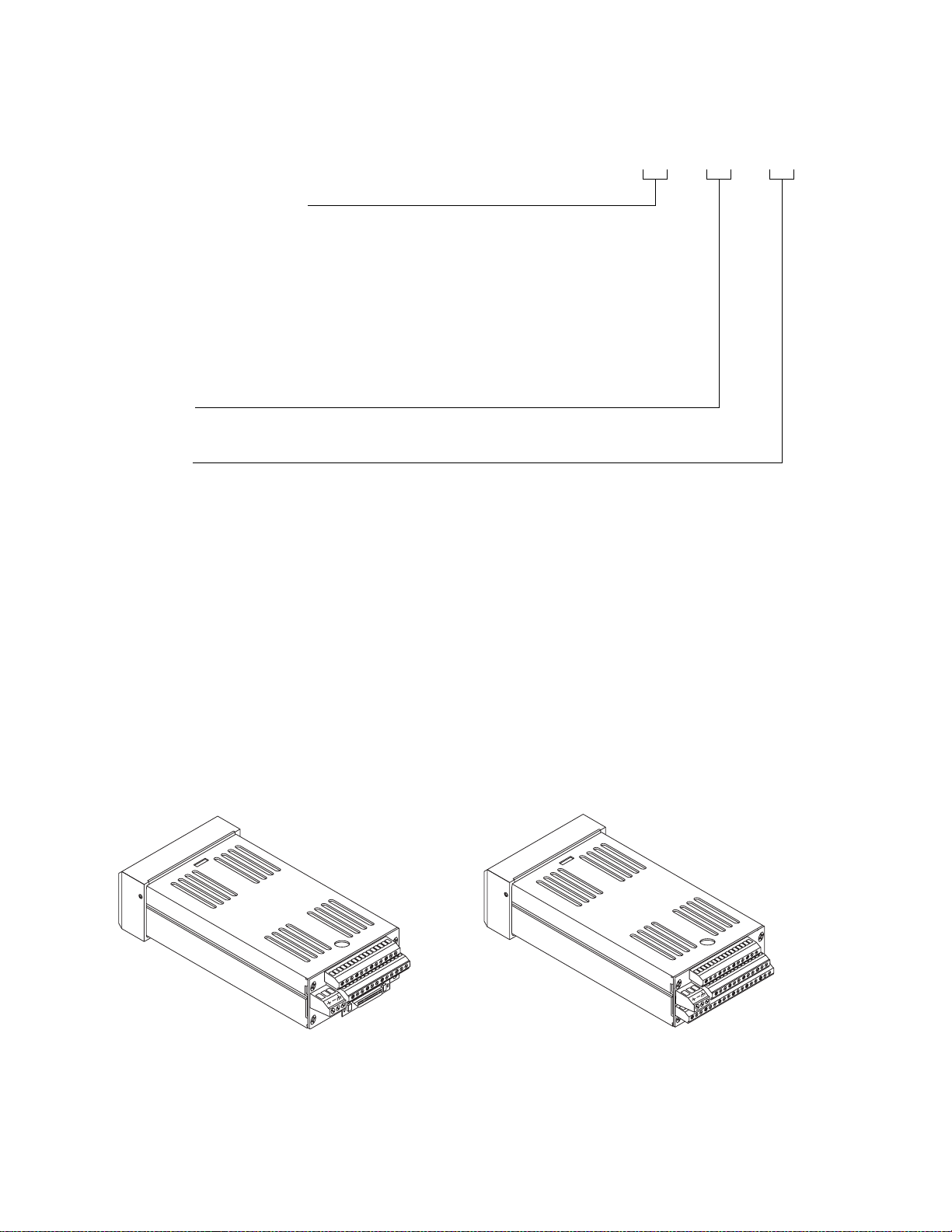
Technical Description
CPC400
Figure 1.2 CPC400 Special Inputs Parts List
This section contains a technical description of each component of the CPC400 series controller.
The CPC400 is housed in a 1/8-DIN panel mount package.
It contains the central processing unit (CPU), random access memory (RAM) with a built-in battery, flash memory,
serial communications, digital I/O, analog inputs, display
and touch keypad.
CPC400 Series
with SCSI Connector
CPC400 Series
with TB18 Connector
Figure 1.3 CPC400 Rear Views
6 Watlow Anafaze Doc. 0600-2900-2000
Page 21
CPC400 Series User’s Guide Chapter 1: System Overview
The CPC400 has the following features:
• Keypad and two-line, 16-character display.
• Screw terminals for the power and analog inputs and
communications.
• Input power of 12 to 24 VÎ (dc) at 1 Amp.
• 50-pin SCSI cable to connect the digital inputs and
outputs to the 50-terminal block (TB50). The CPC400
is available with an 18-terminal block (TB18) in place
of the SCSI connector, as shown in Figure 1.3 on page
6.
• Nonvolatile flash memory for storage of firmware and
programmable logic.
• Battery-backed storage of operating parameters. If a
power loss occurs, the operating parameters are stored
in memory. The battery has a ten-year shelf life, and
it is not used when the controller is on.
• Microprocessor control of all calculations for input signal linearization, PID control, alarms, and communications.
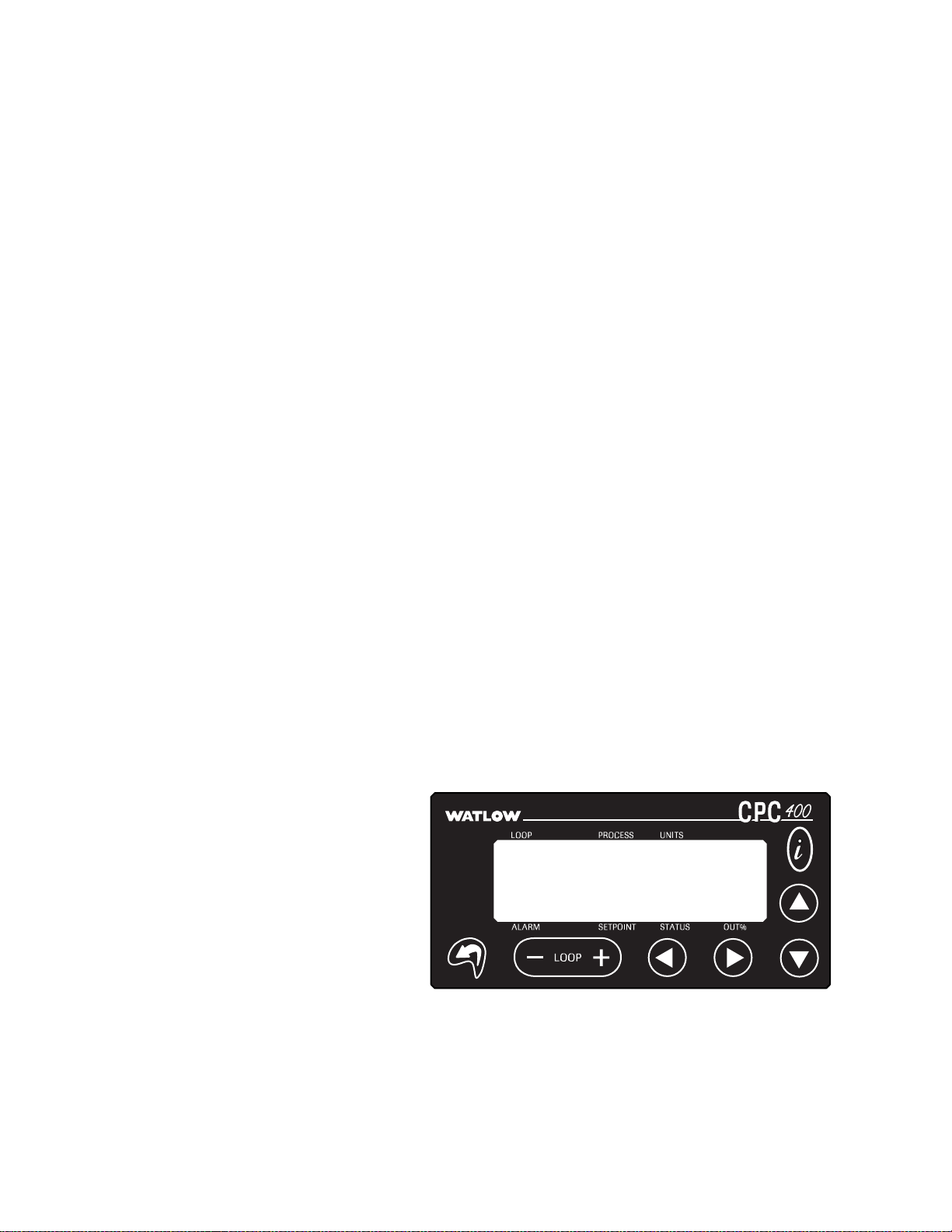
Front Panel Description
The display and keypad provide an intelligent way to operate the controller. The display has 16 alphanumeric or
graphic characters per line. The eight-key keypad allows
you to change the operating parameters, controller functions and displays.
The displays show process variables, set points and output
levels for each loop. A single-loop display, scanning display
and alarm display offer a real-time view of process conditions.
For useful tips, help and menu information, press i from
any screen.
Figure 1.4 CPC400 Front Panel
Doc. 0600-2900-2000 Watlow Anafaze 7
Page 22
Chapter 1: System Overview CPC400 Series User’s Guide
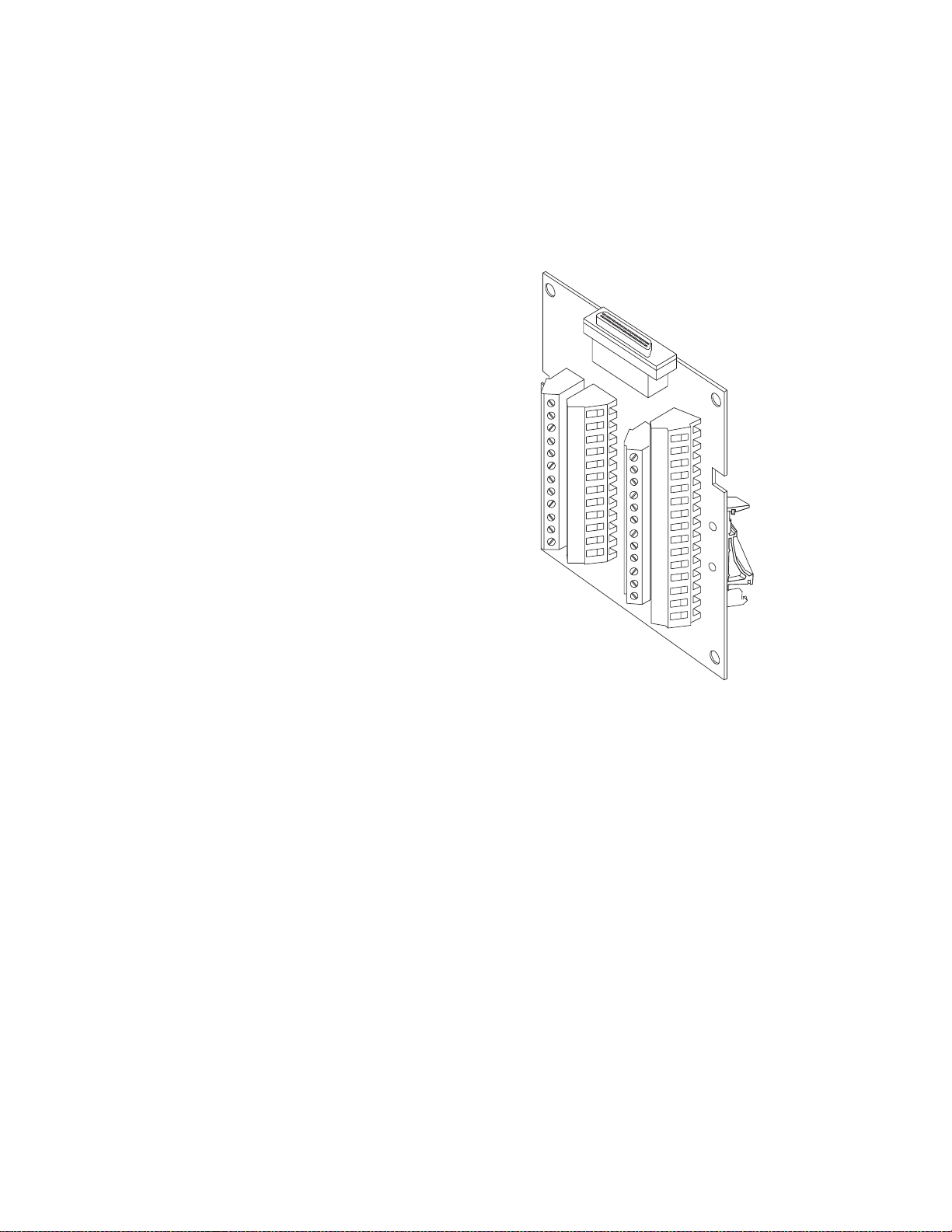
TB50
The TB50 is a screw-terminal interface for control wiring.
It allows you to connect relays, encoders and discrete I/O
devices to the CPC400. The screw terminal blocks accept
wires as large as 18 AWG (0.75 mm2). A 50-pin SCSI cable
connects the TB50 to the CPC400.
CPC400 Cabling
Figure 1.5 TB50
Watlow Anafaze provides cables required to install the
CPC400. A 50-pin SCSI cable connects the TB50 to the
CPC400.
The optional cable used to connect the CPC400 to a computer using EIA/TIA-232 communications has a DB-9 or DB25 connector for the computer and bare wires for connecting to the CPC400.
8 Watlow Anafaze Doc. 0600-2900-2000
Page 23

CPC400 Series User’s Guide Chapter 1: System Overview
Safety
Watlow Anafaze has made every effort to ensure the reliability and safety of this product. In addition, we have provided recommendations that will allow you to safely install
and maintain this controller.
External Safety Devices
The CPC400 controller may fail full-on (100 percent output
power) or full-off (0 percent output power), or may remain
full-on if an undetected sensor failure occurs.
Design your system to be safe even if the controller sends a
0 percent or 100 percent output power signal at any time.
Install independent, external safety devices such as the
Watlow Anafaze TLM-8 that will shut down the system if a
failure occurs.
Typically, a shutdown device consists of an agency-approved high/low process limit controller that operates a
shutdown device such as an mechanical contactor. The limit controller monitors for a hazardous condition such as an
under-temperature or over-temperature fault. If a hazardous condition is detected, the limit controller sends a signal
to open the contactor.
The safety shutdown device (limit controller and contactor)
must be independent from the process control equipment.
WARNING!
The controller may fail in a 0 percent or 100 percent output power state. To prevent death, personal injury, equipment damage or property
damage, install external safety shutdown devices
that operate independently from the process control equipment.
With proper approval and installation, thermal fuses may
be used in some processes.
Doc. 0600-2900-2000 Watlow Anafaze 9
Page 24

Chapter 1: System Overview CPC400 Series User’s Guide
Power-Fail Protection
In the occurrence of a sudden loss of power, the CPC400
controller can be programmed to reset the control outputs
to off (this is the default). The controller can also be configured to restart to data stored in memory.
A memory-based restart might create an unsafe process
condition for some installations. Use a memory-based restart only if you are certain your system will safely restart.
See Power Up Loop Mode on page 100.
When using a computer or host device, you can program the
software to automatically reload desired operating constants or process values on powerup. These convenience
features do not eliminate the need for independent safety
devices.
Contact Watlow Anafaze immediately if you have any questions about system safety or system operation.
10 Watlow Anafaze Doc. 0600-2900-2000
Page 25

2
Installation
This chapter describes how to install the CPC400 series
controller and its peripherals. Installation of the controller
involves the following procedures:
• Determining the best location for the controller
• Mounting the controller and TB50
• Power connection
• Input wiring
• Communications wiring (EIA/TIA-232 or EIA/TIA-
485)
• Output wiring
WARNING!
WARNING!
Doc.0600-2900-2000 Watlow Anafaze 11
Risk of electric shock. Shut off power to your entire process before you begin installation of the
controller.
The controller may fail in a 0 percent or 100 percent power output state. To prevent death, personal injury, equipment damage or property
damage, install external safety shutdown devices
that operate independently from the process control equipment.
Page 26
Chapter 2: Installation CPC400 Series User’s Guide
Typical Installation
Figure 2.1 shows typical installations of the controller with
the TB50 and the TB18 terminal blocks. The type of terminal block you use greatly impacts the layout and wiring of
your installation site. See Figure 2.2 to Figure 2.10 to determine potential space requirements.
We recommend that you read this entire chapter before beginning the installation procedure. This will help you to
carefully plan and assess the installation.
CPC400 with TB50
Signal Inputs
CPC400 with TB18
Signal Inputs
3 Digital Inputs
Pulse Input
11 Digital Outputs (Control, Alarm, Logic)
SCSI Cable
8 Digital Inputs
Pulse Input
35 Digital Outputs
(Control, Alarm, Logic)
CPC400
Power Supply
CPC400
Power Supply
Figure 2.1 CPC400 System Components
12 Watlow Anafaze Doc. 0600-2900-2000
Page 27

CPC400 Series User’s Guide Chapter 2: Installation
Mounting Controller Components
Install the controller in a location free from excessive heat
(>50º C), dust and unauthorized handling. Electromagnetic
and radio frequency interference can induce noise on sensor wiring. Choose locations for the CPC400 and TB50 such
that wiring can be routed clear of sources of interference
such as high voltage wires, power switching devices and
motors.
NOTE!
WARNING!
Recommended Tools
For indoor use only.
To reduce the risk of fire or electric shock, install
the CPC400 in a controlled environment, relatively free of contaminants.
Use any of the following tools to cut a hole of the appropriate size in the panel.
• Jigsaw and metal file, for stainless steel and heavyweight panel doors.
• Greenlee 1/8-DIN rectangular punch (Greenlee part
number 600-68), for most panel materials and thicknesses.
• Nibbler and metal file, for aluminum and lightweight
panel doors.
You will also need these tools:
• Phillips head screwdriver
• 1/8-inch (3 mm) flathead screwdriver for wiring
• Multimeter
Mounting the Controller
Mount the controller before you mount the terminal block
or do any wiring. The controller’s placement affects placement and wiring considerations for the other components
of your system.
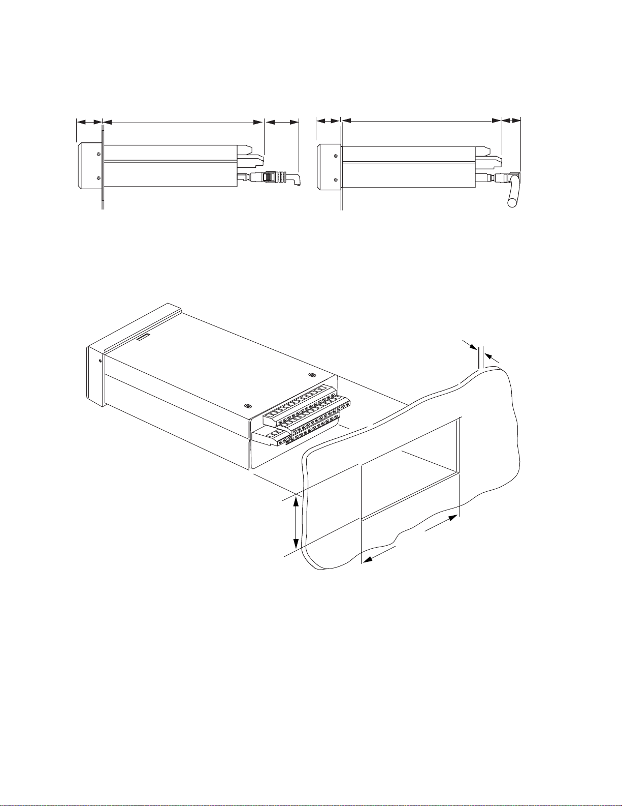
Ensure that there is enough clearance for mounting brackets, terminal blocks, and cable and wire connections. The
controller extends up to 7.0 inches (178 mm) behind the
panel face and the screw brackets extend 0.5 inch (13 mm)
above and below it. If using a straight SCSI cable, allow for
an additional 1.6 inches (41 mm) beyond the terminal
block. If using a right-angle SCSI cable, allow an additional
0.6 inch (15 mm). Refer to Figure 2.2.
Doc. 0600-2900-2000 Watlow Anafaze 13
Page 28
Chapter 2: Installation CPC400 Series User’s Guide
1.0 in.
(25 mm)
7.0 in.
(178 mm)
1.6 in.
(41 mm)
1.0 in.
(25 mm)
7.0 in.
(178 mm)
0.6 in.
(15 mm)
Figure 2.2 Clearance with Straight SCSI Cable (L) and Right-Angle SCSI Cable (R)
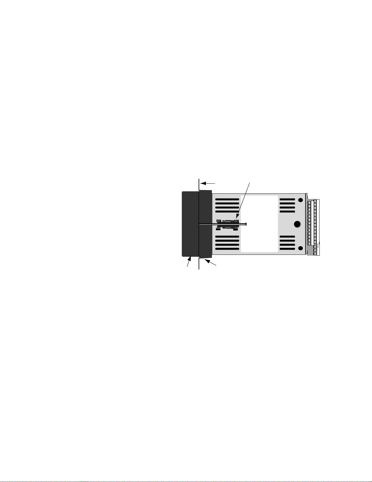
Maximum Panel Thickness
0.2 in. (5 mm)
1.80 ± 0.020 in.
(45.7 ± 0.5 mm)
3.63 ± 0.020 in.
(92.2 ± 0.5 mm)
Figure 2.3 Wiring Clearances
We recommend you mount the controller in a panel not
more than 0.2 in. (5 mm) thick.
1. Choose a panel location free from excessive heat (more
than 50° C [122° F]), dust, and unauthorized handling.
(Make sure there is adequate clearance for the mounting hardware, terminal blocks, and cables. The controller extends 7.0 in. (178 mm) behind the panel.
14 Watlow Anafaze Doc. 0600-2900-2000
Page 29
CPC400 Series User’s Guide Chapter 2: Installation
Allow for an additional 0.60 to 1.60 in. (15 to 41 mm)
beyond the connectors.)
2. Temporarily cover any slots in the metal housing so
that dirt, metal filings, and pieces of wire do not enter
the housing and lodge in the electronics.
3. Cut a hole in the panel 1.80 in. (46 mm) by 3.63 in. (92
mm) as shown below. Use caution; the dimensions given here have 0.02 in. (0.5 mm) tolerances.
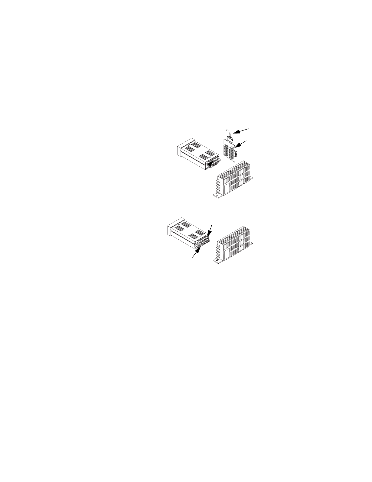
4. Remove the brackets and collar from the processor
module, if they are already in place.
5. Slide the processor module into the panel cutout.
6. Slide the mounting collar over the back of the processor module, making sure the mounting screw indentations face toward the back of the processor module.
.
Bracket (top and bottom)
25
23
21
19
17
15
13
11
9
7
5
3
1
+
26
24
22
20
18
16
14
12
10
8
6
4
2
Bezel
Panel
Mounting Collar
Figure 2.4 Mounting Bracket
7. Loosen the mounting bracket screws enough to allow
for the mounting collar and panel thickness. Place
each mounting bracket into the mounting slots (head
of the screw facing the back of the processor module).
Push each bracket backward then to the side to secure
it to the processor module case.
8. Make sure the case is seated properly. Tighten the installation screws firmly against the mounting collar to
secure the unit. Ensure that the end of the mounting
screws fit into the indentations on the mounting collar.
Doc. 0600-2900-2000 Watlow Anafaze 15
Page 30
Chapter 2: Installation CPC400 Series User’s Guide
Mounting the TB50
There are two ways to mount the TB50: Use the pre-installed DIN rail mounting brackets or use the plastic
standoffs.
TB50
Mounted
with Standoffs
TB50
Mounted to
DIN Rail
Figure 2.5 Mounting the TB50
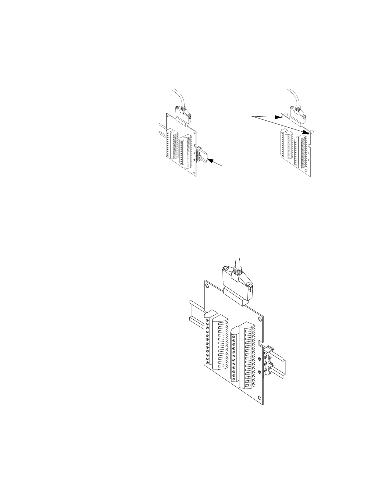
DIN Rail Mounting
Snap the TB50 on to the DIN rail by placing the hook side
on the rail first, then pushing the snap latch side in place.
See Figure 2.6.
Figure 2.6 TB50 Mounted on a DIN Rail (Front)
16 Watlow Anafaze Doc. 0600-2900-2000
Page 31

CPC400 Series User’s Guide Chapter 2: Installation
To remove the TB50 from the rail, use a flathead screw
driver to unsnap the bracket from the rail. See Figure 2.7.
Removal
Catch for
Screwdriver
DIN Rail
Snap Latch
Hook Side
Figure 2.7 TB50 Mounted on DIN Rail (Side)
Mounting with Standoffs
1. Remove the DIN rail mounting brackets from the
TB50.
2. Choose a location with enough clearance to remove the
TB50, its SCSI cable and the controller itself.
3. Mark the four mounting holes.
4. Drill and tap four mounting holes for #6 (3.5 mm)
screws or bolts.
5. Mount the TB50 with four screws or bolts.
There are four smaller holes on the terminal board. Use
these holes to secure wiring to the terminal block with tie
wraps.
0.7 in
(18 mm)
4 Holes for
#6 (3.5 mm)
Bolts or Screws
0.2 in
(5 mm)
3.4 in
(86 mm)
0.2 in
(5 mm)
0.2 in
(5 mm)
2.6 in
(66 mm)
SCSI Connector
3.6 in
(91 mm)
Figure 2.8 Mounting a TB50 with Standoffs
Doc. 0600-2900-2000 Watlow Anafaze 17
Page 32

Chapter 2: Installation CPC400 Series User’s Guide
Mounting the Power Supply
If you use your own power supply for the CPC400, refer to
the power supply manufacturer’s instructions for mounting
information. Choose a Class 2 power supply that supplies
an isolated, regulated 12 to 24VÎ (dc) at 1 A.
Mounting Environment
Leave enough clearance around the power supply so that it
can be removed.
2 Holes for #10 (4.5 mm)
Bolts or Screws
1.4 inch
(36 mm)
Mounting Steps
CAUTION!
0.3 inch
(8 mm)
7.5 inches
(191 mm)
8.1 inches
(206 mm)
0.7 inch
(18 mm)
Figure 2.9 CPC400 Power Supply Mounting
Bracket
When attaching the bracket to the power supply,
use screws that are no longer than 1/4-inch (6
mm) long. Longer screws may extend too far into
the power supply and short to components, damaging the power supply.
1. Attach the bracket to the power supply using the two
center holes in the bracket.
2. Choose a location with enough clearance to remove the
power supply and bracket.
3. Mark the bracket’s two outer holes for mounting.
4. Drill and tap the two mounting holes. The bracket
holes accept up to #10 (4.5 mm) screws.
5. Mount the power supply on the panel.
6. Tighten the screws.
18 Watlow Anafaze Doc. 0600-2900-2000
Page 33

CPC400 Series User’s Guide Chapter 2: Installation
Mounting the Dual DAC or Serial DAC Module
This section describes how to mount the optional Dual DAC
and Serial DAC digital-to-analog converters.
Mounting of the Dual DAC and Serial DAC is essentially
the same, except that the dimensions differ.
Jumpers
The output signal range of the Dual DAC and Serial DAC
modules is configured with jumpers. See Configuring Dual
DAC Outputs on page 163 and Configuring Serial DAC
Outputs on page 162 for information about setting these
jumpers.
Mounting
1. Choose a location. The unit is designed for wall mounting. Install it as close to the controller as possible.
2. Mark and drill four holes for screw mounting. Holes
accommodate #8 (3.5 mm) screws. See Figure 2.10 for
screw locations. Install the unit with the four screws.
Dual DAC
4 Holes for #8 (3.5 mm)
Screws or Bolts
3.62 in
(91 mm)
Electrical
Connectors
Electrical
Connectors
3.7 in
(94 mm)
4.40 in
(112 mm)
0.3 in
(8 mm)
3.00 in
(76 mm)
(17 mm)
1.75 in
(44 mm)
0.37 in
(9 mm)
0.65 in
4 Holes for #8 (3.5 mm)
Screws or Bolts
3.62 in
(91 mm)
Electrical
Connectors
Serial DAC
Electrical
Connectors
4.7 in
(119 mm)
5.40 in
(137 mm)
0.3 in
(8 mm)
3.00 in
(76 mm)
0.37 in
(9 mm)
0.65 in
(17 mm)
1.75 in
(44 mm)
Figure 2.10 Dual DAC and Serial DAC Dimen-
sions
Doc. 0600-2900-2000 Watlow Anafaze 19
Page 34

Chapter 2: Installation CPC400 Series User’s Guide
System Wiring
Successful installation and operation of the control system
can depend on placement of the components and on selection of the proper cables, sensors and peripheral components.
Routing and shielding of sensor wires and proper grounding of components can insure a robust control system. This
section includes wiring recommendations, instructions for
proper grounding and noise suppression, and considerations for avoiding ground loops.
WARNING!
CAUTION!
Wiring Recommendations
To reduce the risk of electrical shock, fire, and
equipment damage, follow all local and national
electrical codes. Correct wire sizes, fuses and
thermal breakers are essential for safe operation
of this equipment.
Do not wire bundles of low-voltage signal and
control circuits next to bundles of high-voltage ac
wiring. High voltage may be inductively coupled
onto the low-voltage circuits, which may damage
the controller or induce noise and cause poor
control.
Physically separate high-voltage circuits from
low-voltage circuits and from CPC400 hardware.
If possible, install high-voltage ac power circuits
in a separate panel.
Follow these guidelines for selecting wires and cables:
• Use stranded wire. (Solid wire can be used for fixed
service; it makes intermittent connections when you
move it for maintenance.)
• Use 20 AWG (0.5 mm2) thermocouple extension wire.
Larger or smaller sizes may be difficult to install, may
break easily or may cause intermittent connections.
• Use shielded wire. The electrical shield protects the
signals and the CPC400 from electrical noise. Connect
one end of the input and output wiring shield to earth
ground.
• Use copper wire for all connections other than thermocouple sensor inputs.
20 Watlow Anafaze Doc. 0600-2900-2000
Page 35

CPC400 Series User’s Guide Chapter 2: Installation
Table 2.1 Cable Recommendations
Function Mfr. P/N
Analog Inputs
RTD Inputs
Thermocouple Inputs T/C Ext. Wire 2 20 0.5 —
Control Outputs and
Digital I/O
Analog Outputs
Computer Communication: EIA/TIA-232,
422 or 485, or 20 mA
Belden 9154
Belden 8451
Belden 8772
Belden 9770
Belden 9539
Belden 9542
Ribbon Cable
Belden 9154
Belden 8451
Belden 9729
Belden 9730
Belden 9842
Belden 9843
Belden 9184
No. of
Wires
2
2
3
3
9
20
50
2
2
4
6
4
6
4
AWG
20
22
20
22
24
24
22 to 14
20
22
24
24
24
24
22
2
mm
0.5
0.5
0.5
0.5
0.2
0.2
0.5 to 2.5
0.5
0.5
0.2
0.2
0.2
0.2
0.5
Maximum
Length
4000 ft. (1219 m)
4000 ft. (1219 m)
6000 ft. (1829 m)
Noise Suppression
—
—
—
—
Symptoms of Noise
The CPC400 outputs are typically used to drive solid-state
relays. These relays may in turn operate more inductive
types of loads such as electromechanical relays, alarm
horns and motor starters. Such devices may generate electromagnetic interference (EMI, or noise). If the controller is
placed close to sources of EMI, it may not function correctly. Below are some tips on how to recognize and avoid problems with EMI.
For earth ground wire, use a large gauge and keep the
length as short as possible. Additional shielding may be
achieved by connecting a chassis ground strap from the
panel to CPC400 case.
If your controller displays the following symptoms, suspect
noise:
• The display screen blanks out and then reenergizes as
if power had been turned off for a moment.
• The process variable value is incorrect on the controller display.
Noise may also damage the digital output circuit such that
the digital outputs will not turn on. If the digital output circuit is damaged, return the controller to Watlow Anafaze
for repair.
Doc. 0600-2900-2000 Watlow Anafaze 21
Page 36

Chapter 2: Installation CPC400 Series User’s Guide
Avoiding Noise
To avoid or eliminate most RFI/EMI noise problems:
• Connect the CPC400 case to earth ground. The
CPC400 system includes noise suppression circuitry.
This circuitry requires proper grounding.
• Separate the 120VÅ (ac) and higher power leads from
the low-level input and output leads connected to the
CPC400 series controller. Do not run the digital I/O or
control output leads in bundles with ac wires.
• Where possible, use solid-state relays (SSRs) instead
of electromechanical relays. If you must use electromechanical relays, avoid mounting them in the same
panel as the CPC400 series equipment.
• If you must use electromechanical relays and you
must place them in a panel with CPC400 series equipment, use a 0.01 microfarad capacitor rated at 1000V
(ac) (or higher) in series with a 47 Ω, 0.5 watt resistor
across the normally-open contacts of the relay load.
This is known as a snubber network and can reduce
the amount of electrical noise.
• You can use other voltage suppression devices, but
they are not usually required. For instance, you can
place a metal oxide varistor (MOV) rated at 130VÅ (ac)
for 120VÅ (ac) control circuits across the load, which
limits the peak ac voltage to about 180VÅ (ac) (Watlow
Anafaze part number 26-130210-00). You can also
place a transorb (back-to-back zener diodes) across the
digital output, which limits the digital output voltage.
Å
Additional Recommendations for a Noise Immune System
We strongly recommended the following:
• Isolate outputs through solid-state relays, where possible.
• Isolate digital inputs from ground through solid-state
relays. If this is not possible, then make sure the digital input is the only connection to earth ground other
than the chassis ground.
22 Watlow Anafaze Doc. 0600-2900-2000
Page 37

CPC400 Series User’s Guide Chapter 2: Installation
Ground Loops
Ground loops occur when current passes from the process
through the controller to ground. This can cause instrument errors or malfunctions.
The best way to avoid ground loops is to minimize unnecessary connections to ground. Do not connect any of the following terminals to each other or to earth ground:
• Power supply dc common
• TB1 terminals 5, 6, 11, 12 (analog common)
• TB1 terminal 17 (reference voltage common)
• TB1 terminals 23, 24 (communications common)
• TB2 terminal 2 (dc power common)
Power Connections
This section explains how to make power connections to the
CPC400 and the TB50.
TB2
(to power
supply)
TB2
(to power
supply)
TB1
(to signal
inputs
TB18
(to digital
outputs)
Figure 2.11 CPC400 Series Controller with
TB18
TB1
(to signal
inputs
SCSI-2
(to TB50)
Figure 2.12 CPC400 Series Controller with
TB50
Doc. 0600-2900-2000 Watlow Anafaze 23
Page 38

Chapter 2: Installation CPC400 Series User’s Guide
Wiring the Power Supply
WARNING!
Use a power supply with a Class 2 rating only. UL
approval requires a Class 2 power supply.
Connect power to the controller before any other connections, This allows you to ensure that the controller is working before any time is taken installing inputs and outputs.
Table 2.2 Power Connections
Function Power Supply CPC400 TB2
DC Power
(Controller)
DC Common
Earth Ground Ground
1. Connect the dc common terminal on the power supply
to the dc common (-) terminal on CPC400 TB2.
2. Connect the positive terminal on the power supply to
the dc positive (+) terminal on CPC400 TB2.
3. If using an isolated dc output or another power supply
to power the loads, connect the dc common of the supply powering the loads to the dc common of the supply
powering the controller.
4. Use the ground connector on TB2 for chassis ground.
This terminal is connected to the CPC400 chassis and
must be connected to earth ground.
5. Connect 120/240VÅ (ac) power to the power supply.
+12 to 24VÎ (dc) +
12 to 24VÎ (dc)
Common
-
NOTE!
NOTE!
24 Watlow Anafaze Doc. 0600-2900-2000
Connect the dc common of the power supply
used for loads to the dc common of the supply
powering the controller. If the supplies are not referenced to one another, the controller’s outputs
will not be able to switch the loads.
When making screw terminal connections, tighten to 4.5 to 5.4 in.-lb. (0.5 to 0.6 Nm).
Page 39

CPC400 Series User’s Guide Chapter 2: Installation
CAUTION!
CAUTION!
NOTE!
Without proper grounding, the CPC400 may not
operate properly or may be damaged.
To prevent damage from incorrect connections,
do not turn on the ac power before testing the
connections as explained in Testing the System
on page 26.
Do not connect the controller’s dc common
(COM) to earth ground . Doing so will defeat the
noise protection circuitry, making measurements
less stable.
Power Supply
+V1 (5V)
0 (5V COM)
+V2 (+15V)
Add jumper *
solid-state relay
C
G
OMV
N
+
D
CPC400
**
solid-state relay
COM (15V COM)
-V2 (-15V)
(Ground)
ACL (AC Line)
ACN (AC Neutral)
white
120/240
VÅ (ac)
Supply
** Connect terminals to ac panel ground.
N
black
H
green
G
**
* If using 5VÎ (dc) for outputs, jumper 5V common to 15V common.
1 2 3 4
+
5
solid-state relay
Serial DAC
C
O
M
solid-state relay
Figure 2.13 Power Connections with the
CPC400 Power Supply
Doc. 0600-2900-2000 Watlow Anafaze 25
Page 40

Chapter 2: Installation CPC400 Series User’s Guide
Connecting the TB50 to the CPC400
1. Connect the SCSI cable to the controller.
2. Connect the SCSI cable to the TB50.
Testing the System
This section explains how to test the controller after installation and prior to making field wiring connections.
TB50 or TB18 Test
Use this procedure to verify that the TB50 or TB18 is properly connected and supplied with power:
1. Turn on power to the CPC400. The display should first
show Calculating checksum, and then show the singleloop display. If you do not see these displays, disconnect power and check wiring and power supply output.
2. Measure the +5VÎ dc supply at the TB50 or TB18:
a) Connect the voltmeter’s common lead to TB50 ter-
minal 3 or TB18 terminal 2.
b) Connect the voltmeter’s positive lead to TB50 or
TB18 terminal 1. The voltage should be +4.75 to
+5.25VÎ dc.
Digital Output Test
NOTE!
Use this procedure to test the controller outputs before
loads are connected. If using it at another time for troubleshooting, disconnect loads from outputs before testing.
1. Connect a 500 Ω to 100 kΩ resistor between TB50 or
TB18 terminal 1 and a digital output terminal. See
Table 2.5 on page 37 for TB18 connections or Table 2.6
on page 38 for TB50 connections.
2. Connect the voltmeter’s positive lead to terminal 1 on
the TB50 or TB18.
3. Connect the voltmeter’s common lead to the digital
output terminal.
4. Use the digital output test in the
the digital output on and off (see Test Digital Output 1 to
35 on page 132). When the output is on, the output voltage should be less than 1 V. When the output is off, the
output voltage should be between 4.75 and 5.25 V.
By default, heat outputs are enabled. Only disabled
outputs may be turned on using the manual I/O test.
To test heat outputs, set the corresponding loop to
manual mode 100 percent output. See Changing the
Control Mode and Output Power on page 55.
I/O tests
menu to turn
26 Watlow Anafaze Doc. 0600-2900-2000
Page 41

CPC400 Series User’s Guide Chapter 2: Installation
Digital Input Test
Use the following procedure to test digital inputs before
connecting to field devices:
1. Disconnect any system wiring from the input to be
tested.
2. Go to the Digital inputs test in the I/O tests menu.
This test shows whether the digital inputs are off
(open) or on (closed).
3. Attach a wire to the terminal of the digital input you
want to test. See Table 2.5 on page 37 for TB 18 con-
nections or Table 2.6 on page 38 for TB50 connections.
a) When the wire is connected only to the digital in-
put terminal, the digital input test should show
that the input is off (open).
b) When you connect the other end of the wire to the
controller common (TB50 terminal 3 or TB18 terminal 2), the digital input test should show that
the input is on (closed).
Sensor Wiring
CAUTION!
This section describes how to properly connect thermocouples, RTDs, current and voltage inputs to the controller.
The controller can accept any mix of available input types.
Some input types require that special scaling resistors be
installed (generally done by Watlow Anafaze before the
controller is delivered).
All inputs are installed at the “CH” input connectors (TB1)
at the back of the controller. The illustrations below show
the connector locations for all CPC400 series controllers.
Never run input leads in bundles with high power
wires or near other sources of EMI. This could inductively couple voltage onto the input leads and
damage the controller, or could induce noise and
cause poor measurement and control.
Doc. 0600-2900-2000 Watlow Anafaze 27
Page 42

Chapter 2: Installation CPC400 Series User’s Guide
Figure 2.14 CPC400 Connector Locations
Input Wiring Recommendations
Use multicolored stranded shielded cable for analog inputs.
Watlow Anafaze recommends that you use 20 AWG wire
(0.5 mm2). If the sensor manufacturer requires it, you can
also use 24 or 22 AWG wiring (0.2 mm2). Most inputs use a
shielded twisted pair; some require a three-wire input.
The controller accepts the following inputs without any
special scaling resistors:
• J, K, T, S, R, B and E thermocouples.
• Process inputs with ranges between -10 and +60 mV.
To avoid thermocouple open alarms on unused inputs, ei-
ther set the Input type parameter to skip or jumper the input.
Thermocouple Connections
Connect the positive lead of the thermocouple to the IN+
terminal for one of the loops, and connect the negative lead
to the corresponding IN- terminal.
28 Watlow Anafaze Doc. 0600-2900-2000
Page 43

CPC400 Series User’s Guide Chapter 2: Installation
Use 18 or 20 AWG (0.5 or 0.75 mm2) for all thermocouple
inputs. Most thermocouple wire is solid, unshielded wire.
When using shielded wire, ground one end only.
CAUTION!
CH IN+
CH IN-
White
Red
Shield (if present)
Earth Ground
at Process End
Type J
Thermocouple
Figure 2.15 Thermocouple Connections
Connect the earth ground terminal on TB2 to a
good earth ground, but do not connect the analog
common to earth ground. The CPC400 uses a
floating analog common for sensor measurements. The noise protection circuits on the sensor inputs function correctly only if the controller
is correctly installed. See Ground Loops on page
23.
RTD Input Connections
RTD input requires scaling resistors. Watlow Anafaze recommends that you use a 100 Ω, three-wire platinum RTD
to prevent reading errors due to cable resistance. If you use
a two-wire RTD, jumper the negative input to common. If
you must use a four-wire RTD, leave the fourth wire uncon-
nected.
IN +
CH
100 Ω RTD
IN -
CH
Com
Figure 2.16 RTD Connections
Doc. 0600-2900-2000 Watlow Anafaze 29
Page 44

Chapter 2: Installation CPC400 Series User’s Guide
Reference Voltage Terminals
The +5V Ref and Ref Com terminals are provided to power
external bridge circuits for special sensors. Do not connect
any other type of device to these terminals.
Voltage Input Connections
Voltage input requires scaling resistors. Special input resistors installed at Watlow Anafaze divide analog input
voltages such that the controller sees a -10 to 60 mV signal
on the loop.
Current Input Connections
CH IN+
CH IN-
Device with
Voltage
Output
Figure 2.17 Voltage Signal Connections
Current input requires scaling resistors. Special input resistors installed at Watlow Anafaze for analog current signals are such that the controller sees a -10 to 60 mV signal
across its inputs for the loop.
CH IN+
CH IN-
Device with
Current
Output
Figure 2.18 Current Signal Connections
30 Watlow Anafaze Doc. 0600-2900-2000
Page 45

CPC400 Series User’s Guide Chapter 2: Installation
Pulse Input Connections
The CPC400 can accept a pulse input up to 2000 Hz from a
device such as an encoder. The frequency of this input is
scaled with user-configured parameters; see Setting Up a
Process or Pulse Input on page 58. This scaled value is the
process variable for loop 5 on a CPC404, or loop 9 on a
CPC408.
The CPC400 can accommodate encoder signals up to 24VÎ
(dc) using a voltage divider or can power encoders with the
5VÎ (dc) from the TB50 or TB18. The following figures
show how to connect encoders. A pull-up resistor in the
CPC400 allows open collector inputs to be used.
NOTE!
If the signal on the pulse input exceeds 10kHz the
controller’s operation may be disrupted. Do not
connect the pulse input to a signal source that
may exceed 10kHz.
CPC400 and TB50 or TB18
+5VÎ (dc)
10 kΩ
Figure 2.19 Encoder with 5V
CPC400 and TB50 or TB18
+5VÎ (dc)
10 kΩ
Pulse Input
Com
Pulse Input
Com
R2
Encoder
ÎÎ
ÎÎ
(dc) TTL Signal
R1
Encoder
Figure 2.20 Encoder Input with Voltage Divider
For encoders with signals greater than 5VÎ (dc), use a voltage divider to drop the voltage to 5 volts at the input. Use
appropriate values for R1 and R2 depending on the encoder
excitation voltage. Do not exceed the specific current load
on the encoder.
Doc. 0600-2900-2000 Watlow Anafaze 31
Page 46

Chapter 2: Installation CPC400 Series User’s Guide
Wiring Control and Digital I/O
This section describes how to wire and configure the control
outputs for the CPC400 series controller. The CPC400 provides dual control outputs for each loop. These outputs can
be enabled or disabled, and are connected through a TB50
or TB18.
NOTE!
Control outputs are connected to controller common when the control output is on. If you connect
external devices that may have a low side at a
voltage other than controller ground, you may
create ground loops. To prevent ground loops,
use isolated solid-state relays and isolate the
control device inputs.
Output Wiring Recommendations
When wiring output devices, use multicolored, stranded,
shielded cable for analog outputs and digital outputs connected to panel-mounted solid-state relays.
• Analog outputs usually use a twisted pair.
• Digital outputs usually have 9 to 20 conductors, depending on wiring technique.
Cable Tie Wraps
After you wire outputs to the TB50, install the cable tie
wraps to reduce strain on the connectors. Each row of terminals has a cable tie wrap hole at one end. Thread the cable tie wrap through the cable tie wrap hole. Then, wrap
the cable tie wrap around the wires attached to that terminal block.
Digital Outputs
The CPC400 provides dual control outputs for up to eight
loops. By default, heat outputs are enabled and cool outputs are disabled. If the heat or cool output is disabled for
a loop, then the output is available for alarms or programmable logic. The CPU watchdog timer output can be used
to monitor the state of the controller; see CPU Watchdog
Timer on page 35.
32 Watlow Anafaze Doc. 0600-2900-2000
Page 47

CPC400 Series User’s Guide Chapter 2: Installation
Table 2.3 Digital Output States and Values
Stored in the Controller
State
Off 0 Open circuit
On 1 Sinking current to controller common
1
Read and write these values through serial communications and Log-
icPro programs.
All digital outputs sink current to controller common when
on. The load may powered by the 5VÎ (dc) supplied by the
controller at the TB50, or by an external power supply.
When using an external power supply, bear in mind:
• The CPC400 power supply available from Watlow
Anafaze includes a 5VÎ (dc) supply. When using it to
supply output loads, connect the 5VÎ (dc) common to
the 15VÎ (dc) common at the power supply.
• Do not exceed +24 volts.
• If you connect the external load to earth ground, or if
you cannot connect it as shown in Figure 2.21, then
use a solid-state relay.
The outputs conduct current when they are on. The maximum current sink capability is 60 mA at 24VÎ (dc). The
outputs cannot “source” current to a load.
Value
1
Description
Using Internal Power Supply
TB50 or TB18
+5VÎ dc
Digital Output 1
Digital Output 2
Figure 2.21 Digital Output Wiring
Loads
Using External Power Supply
External
Power
Supply
to earth ground or
equipment ground
TB50 or TB18
Control Common
Digital Output 1
Digital Output 2
+
-
Do not connect
Loads
Doc. 0600-2900-2000 Watlow Anafaze 33
Page 48

Chapter 2: Installation CPC400 Series User’s Guide
Configuring Outputs
As you choose outputs for control and alarms, bear in mind
the following points:
• You can enable or disable the control outputs. By default, heat outputs are enabled and cool outputs are
disabled.
• You can program each control output individually for
on/off, time proportioning, distributed zero-crossing or
Serial DAC control.
• You can individually program each control output for
direct or reverse action.
• Alarm outputs other than the global alarm are nonlatching. See Global Alarm on page 67.
• Alarms can be suppressed during process start up and
for preprogrammed durations. See Power Up Alarm
Delay on page 100.
• Alarm outputs can be configured, as a group, to sink to
output during an alarm or stop current flow during an
alarm. See Digital Output Alarm Polarity on page 103.
Control and Alarm Output Connections
Typically control and alarm outputs use external opticallyisolated solid-state relays (SSRs). SSRs accept a 3 to 32VÎ
(dc) input for control, and some can switch up to 100 Amps
at 480VÅ (ac). For larger currents, use silicon control rectifier (SCR) power controllers up to 1000 Amps at 120 to
600VÅ (ac). You can also use SCRs and a Serial DAC for
phase-angle fired control.
The 34 control and alarm outputs are open collector outputs referenced in the CPC400’s common. Each output
sinks up to 60 mAdc to the controller common when on.
NOTE!
Control outputs are sink outputs. They sink current when the output is on. Connect them to the
negative side of solid-state relays.
Figure 2.22 shows sample heat, cool and alarm output connections.
34 Watlow Anafaze Doc. 0600-2900-2000
Page 49

CPC400 Series User’s Guide Chapter 2: Installation
CPU Watchdog Timer
Solid-State
Relay
TB50 or TB18
Solid-State
Relay
+-
Solid-State
Relay
+-
Heat Output
Cool Output
Alarm Output
+5VÅ (ac)
Figure 2.22 Sample Heat, Cool and Alarm Out-
put Connections
TB50 or TB18
Heat Output
Cool Output
Alarm Output
Common
Solid-State
Relay
+-
- PS +
Solid-State
Relay
+-
Solid-State
Relay
Figure 2.23 Output Connections Using Exter-
nal Power Supply
The CPU watchdog timer constantly monitors the microprocessor. It is a sink output located on TB50 terminal 6 or
TB18 terminal 3. The output can be connected to an external circuit or device to monitor whether the controller is
powered and operational. Do not exceed the 5VÎ (dc), 10
mAdc rating for the watchdog output. The output is on
(low) when the microprocessor is operating; when it stops
operating, the output goes off (high).
Figure 2.24 and Figure 2.25 show the recommended circuit
for the watchdog timer output for the TB50 and the TB18.
+-
+-
TB50
+ 5VÎ (dc)
(Terminal 1)
Watchdog Timer
(Terminal 6)
+
Solid-State Relay
-
Figure 2.24 TB50 Watchdog Timer Output
TB18
+ 5VÎ (dc)
(Terminal 1)
Watchdog Timer
(Terminal 3)
+
Solid-State Relay
-
Figure 2.25 TB18 Watchdog Timer Output
Doc. 0600-2900-2000 Watlow Anafaze 35
Page 50

Chapter 2: Installation CPC400 Series User’s Guide
Digital Inputs
All digital inputs are transistor-transistor logic (TTL) level
inputs referenced to controller common and the internal
+5V power supply of the CPC400.
When an input is connected to the controller common, the
input is considered on. Otherwise, the input is considered
off. Most features that use the digital inputs can be userconfigured to activate when an input is either on or off.
In the off state, internal 10 kΩ resistors pull the digital inputs high to 5VÎ (dc) with respect to the controller common.
Table 2.4 Digital Input States and Values
Stored in the Controller
External Switching Device
State
Off 0 Open circuit
On 1
1
Read these values through serial communications and LogicPro pro-
grams.
To ensure that the inputs are reliably switched, use a
switching device with the appropriate impedances in the on
and off states and do not connect the inputs to external
power sources.
When off, the switching device must provide an impedance
of at least 11 kΩ to ensure that the voltage will rise to
greater than 3.7VÎ (dc). When on, the switch must provide
not more than 1 kΩ impedance to ensure the voltage drops
below 1.3VÎ (dc).
To install a switch as a digital input, connect one lead to the
common terminal on the TB50 (terminals 3 and 4) or TB18
(terminal 2). Connect the other lead to the desired digital
input terminal on the TB50 (terminals 43 to 50) or TB18
(terminals 16 to 18).
Value
1
Digital input connected to controller
common
Description
TB50
Input
Control Com
External
Switching
Device
Figure 2.26 Wiring Digital Inputs
36 Watlow Anafaze Doc. 0600-2900-2000
Page 51

CPC400 Series User’s Guide Chapter 2: Installation
Functions Activated by Digital Inputs
Use digital inputs to activate the following functions:
• Load a job that is stored in controller memory. See
BCD Job Load on page 97.
• Change all loops to manual mode at specified output
levels. See Mode Override on page 99.
• Enable thermocouple short detection. See Thermocou-
ple Short Alarm on page 101.
• Restore automatic control after a failed sensor has been
repaired. See Restore Automatic Mode on page 114.
TB18 Connections
Table 2.5 TB18 Connections
Control Output
1
Terminal Function CPC404 CPC408
1 +5VÎ (dc)
2 CTRL COM
3 Watchdog timer
4 Global alarm
5 Output 1 Loop 1 heat Loop 1 heat
6 Output 2 Loop 2 heat Loop 2 heat
7 Output 3 Loop 3 heat Loop 3 heat
8 Output 4 Loop 4 heat Loop 4 heat
9 Output 5 Pulse loop heat Loop 5 heat
10 Output 6 Loop 1 cool Loop 6 heat
11 Output 7 Loop 2 cool Loop 7 heat
12 Output 8 Loop 3 cool Loop 8 heat
13 Output 9 Loop 4 cool Pulse loop heat
14 Output 10 Pulse loop cool Loop 1 cool
15
Output 34
2
Serial DAC clock Serial DAC clock
16 Input 1
17 Input 2
18 Input 3/Pulse input
1
The indicated outputs are dedicated for control when enabled in the
loop setup. If one or both of the outputs are disabled for a loop, then the
corresponding digital outputs become available for alarms or programmable logic.
2
If you install a Watlow Anafaze Serial DAC, the CPC400 series controller uses digital output 34 for a clock line. You cannot use output 34 for
anything else if a Serial DAC is installed.
Doc. 0600-2900-2000 Watlow Anafaze 37
Page 52

Chapter 2: Installation CPC400 Series User’s Guide
TB50 Connections
Table 2.6 TB50 Connections
Control Output
Ter-
minal
1
3 CTRL COM 4 CTRL COM
5 Not Used 6 Watchdog
7 Pulse Input 8 Global Alarm
9 Output 1 Loop 1 heat Loop 1 heat 10
11 Output 2 Loop 2 heat Loop 2 heat 12 Output 33
13 Output 3 Loop 3 heat Loop 3 heat 14 Output 32
15 Output 4 Loop 4 heat Loop 4 heat 16 Output 31
17 Output 5 Loop 5 heat Pulse loop
19 Output 6 Loop 6 heat Loop 1 cool 20 Output 29
21 Output 7 Loop 7 heat Loop 2 cool 22 Output 28
23 Output 8 Loop 8 heat Loop 3 cool 24 Output 27
25 Output 9 Pulse loop
27 Output 10 Loop 1 cool Pulse loop
29 Output 11 Loop 2 cool 30 Output 24
31 Output 12 Loop 3 cool 32 Output 23
33 Output 13 Loop 4 cool 34 Output 22
35 Output 14 Loop 5 cool 36 Output 21
37 Output 15 Loop 6 cool 38 Output 20
39 Output 16 Loop 7 cool 40 Output 19
41 Output 17 Loop 8 cool 42 Output 18 Pulse loop
43 Input 1 44 Input 2
45 Input 3 46 Input 4
47 Input 5 48 Input 6
49 Input 7 50 Input 8
Function CPC408 CPC404
+5VÎ (dc)
heat
1
Ter-
minal
2
18 Output 30
heat
Loop 4 cool 26 Output 26
28 Output 25
cool
1
The indicated outputs are dedicated for control when enabled in the
loop setup. If one or both of a loop’s outputs are disabled, the corresponding digital outputs become available for alarms or programmable
logic.
2
If you install a Watlow Anafaze Serial DAC, the CPC400 uses digital
output 34 (terminal 10) for a clock line. You cannot use output 34 for
anything else if a Serial DAC is installed.
Function CPC408 CPC404
+5VÎ (dc)
Timer
Output 34
2
Control Output
cool
1
38 Watlow Anafaze Doc. 0600-2900-2000
Page 53

CPC400 Series User’s Guide Chapter 2: Installation
Analog Outputs
Analog outputs can be provided by using a Dual DAC or Serial DAC module to convert the open collector outputs from
the controller. Use multicolored stranded shielded cable for
analog outputs. Analog outputs generally use a twisted
pair wiring. The following sections describe how to connect
the Dual DAC and Serial DAC modules to power the controller outputs and the load.
Wiring the Dual DAC
A Dual DAC module includes two identical circuits. Each
can convert a distributed zero cross (DZC) signal from the
controller to a voltage or current signal. Watlow Anafaze
strongly recommends using a power supply separate from
the controller supply to power the Dual DAC. Using a separate power supply isolates the controller’s digital logic circuits and analog measurement circuits from the frequently
noisy devices that take the analog signal from the Dual
DAC.
Several Dual DAC modules may be powered by one power
supply. Consult the Specifications chapter for the Dual
DAC’s power requirements. Also note in the specifications
that the Dual DAC does not carry the same industry approvals as the Serial DAC.
TB50 or TB18
+5V 1
Control Output
mA Load
12 to 24VÎÎÎÎ (dc) Power Supply
+
-
+ -
Dual DAC
+5V CTRL Supply
1
DZC CTRL PID Output
2
3
+12/24V
Power Supply
+VÎ (dc) Load Connection
4
-mAdc Load Connection
5
-External Power
6
Supply/ VÎ (dc) Load
Connection
Î
(dc) External
Figure 2.27 Dual DAC with Current Output
Doc. 0600-2900-2000 Watlow Anafaze 39
Page 54

Chapter 2: Installation CPC400 Series User’s Guide
Wiring the Serial DAC
+ -
Dual DAC
1
+5V CTRL Supply
DZC CTRL PID Output
2
+12/24V
3
Power Supply
4
+VÎ (dc) Load Connection
-mAdc Load Connection
5
6
-External Power
Supply/ VÎ (dc) Load
Connection
Î
(dc) External
TB50 or TB18
+5V 1
PID Loop Output
+
Vdc Load
-
12 to 24VÎÎÎÎ (dc) Power Suppl y
Figure 2.28 Dual DAC with Voltage Output
The Serial DAC provides a robust analog output signal.
The module converts the proprietary Serial DAC signal
from the controller’s open collector output in conjunction
with the clock signal to an analog current or voltage. See
Figure 2.29 for wiring. The Serial DAC is user-configurable
for voltage or current output through firmware configuration. See Configuring Serial DAC Outputs on page 162.
The Serial DAC optically isolates the controller’s control
output from the load. When a single Serial DAC is used, it
may be powered by the 5V
external power supply referenced to the controller’s power
supply. When using multiple Serial DACs, the controller
cannot provide sufficient current; use the 5VÎ (dc) output
from the CPC400 power supply.
Î (dc) found on the TB50 or by an
40 Watlow Anafaze Doc. 0600-2900-2000
Page 55

CPC400 Series User’s Guide Chapter 2: Installation
TB50 or TB18
Serial DAC Clock
Figure 2.29 Single/Multiple Serial DACs
Serial Communications
Controller
Power Supply
+5 V
5 V Common
15 V Common
Control Output
Daisy chain up to
16 Serial DACs
Serial DAC
+5V In
1
COM In
2
CLK In
3
Data In
4
5
+ Out
- Out
6
Load
-
+
EIA/TIA-232 Interface
The CPC400 series controllers are factory-configured for
EIA/TIA-232 communications unless otherwise specified
when purchased. However, the communications are jumper-selectable, so you can switch between EIA/TIA-232 and
EIA/TIA-485. See Changing the Hardware Communica-
tions Protocol on page 157.
EIA/TIA-232 provides communication to the serial port of
an IBM PC or compatible computer. It is used for singlecontroller installations where the cable length does not exceed 50 feet (15 m).
The EIA/TIA-232 interface is a standard three-wire interface. Table 2.7 shows EIA/TIA-232 connections for 25-pin
and 9-pin connectors or cables that are supplied by the factory.
EIA/TIA-232 may be used to connect a computer through a
232-to-485 converter to an EIA/TIA-485 communications
network with up to 32 CPC400 controllers.
Doc. 0600-2900-2000 Watlow Anafaze 41
Page 56

Chapter 2: Installation CPC400 Series User’s Guide
Table 2.7 EIA/TIA-232 Connections
Wire
Color
White TX Pin 26 RX Pin 2 RX Pin 3
Red RX Pin 25 TX Pin 3 TX Pin 2
Black GND Pin 23 GND Pin 5 GND Pin 7
Green GND Pin 24 N/U Pin 9 N/U Pin 22
Shield N/C GND Pin 5 GND Pin 7
Jumpers in EIA/TIA-232 Connectors
Some software programs and some operator interface terminals require a clear to send (CTS) signal in response to
their request to send (RTS) signal, or a data set ready
(DSR) in response to their data terminal ready (DTR). The
CPC400 is not configured to receive or transmit these signals. To use such software with the CPC400, jumper the
RTS to the CTS and the DTR to the DSR in the DB connector. Table 2.8 lists the standard pin assignments for DB-9
and DB-25 connectors.
Table 2.8 RTS/CTS and DSR/DTR Pins in
CPC400
TB1
DB 9
Connector
DB 25
Connector
DB-9 and DB-25 Connectors
DB-9 DB-25
RTS 7 4
CTS 8 5
DTR 4 20
DSR 6 6
Cables manufactured by Watlow Anafaze for EIA/TIA-232
communications include these jumpers. Neither WAT-
VIEW nor LogicPro software requires these jumpers.
EIA/TIA-232
cable
Figure 2.30 Connecting One CPC400 to a Com-
puter Using EIA/TIA-232
42 Watlow Anafaze Doc. 0600-2900-2000
Page 57

CPC400 Series User’s Guide Chapter 2: Installation
EIA/TIA-485 Interface
To communicate with more than one CPC400 series controller on a controller network, or to use communication cable lengths greater than 50 feet (15 m) from PC to
controller, you must use EIA/TIA-485 communications.
When using EIA/TIA-485 communications, you must attach a 232-to-485 converter to the computer. Figure 2.31
and Figure 2.32 show the recommended system wiring.
Personal
Computer
232-to 485
Converter
TXA/TDA/TX-
TXB/TDB/TX+
RXA/RDA/RX-
RXB/RDB/RX+
First
CPC400
JU1
RXA 25
RXB 23
TXA 26
TXB 24
A
B
Do not
connect
shield to
CPC400.
Last
CPC400
JU1
RXA 25
RXB 23
TXA 26
TXB 24
Figure 2.31 Four-Wire EIA/TIA-485 Wiring
232-to 485
Converter
TXA/TDA/TX-
First
CPC400
JU1
RXA 25
Last
CPC400
A
B
JU1
RXA 25
A
B
A
B
TXB/TDB/TX+
RXB 23
RXB 23
Personal
Computer
RXA/RDA/RX-
RXB/RDB/RX+
TXA 26
TXB 24
Do not
connect
shield to
CPC400.
TXA 26
TXB 24
Figure 2.32 Two-Wire EIA/TIA-485 Wiring
Doc. 0600-2900-2000 Watlow Anafaze 43
Page 58

Chapter 2: Installation CPC400 Series User’s Guide
Cable Recommendations
Watlow Anafaze recommends Belden 9843 cable or its
equivalent. This cable includes three 24 AWG (0.2 mm2),
shielded twisted pairs. It should carry signals of up to
19200 baud with acceptable losses for up to 4000 feet (1220
m).
EIA/TIA-485 Network Connections
Watlow Anafaze recommends that you use a single daisy
chain configuration rather than spurs. Run a twisted-pair
cable from the host or converter to the first CPC400, and
from that point run a second cable to the next CPC400, and
so on. See Figure 2.33.
If necessary for servicing, instead of connecting each controller directly to the next, install a terminal strip or connector as close as possible to each CPC400, run a
communications cable from one terminal strip to the next
and connect the controllers to the bus with short lengths of
cable.
To avoid unacceptable interference, use less than 10 feet
(3 m) of cable from the terminal or connector to the CPC400
serial port.
Refer to Termination on page 45 for more on terminating
resistors.
Connect the shield drain to earth ground only at the computer or host end.
232 Communications 485 Communications
Serial Port
Shielded Twisted Pair Cable
232-to-485
Converter
First CPC400
Second CPC400
Figure 2.33 Recommended System
Connections
Last CPC400
44 Watlow Anafaze Doc. 0600-2900-2000
Page 59

CPC400 Series User’s Guide Chapter 2: Installation
Signal Common
For usual installations, do not connect the dc commons of
the controllers together or to the converter or host device.
Termination
For EIA/TIA-485 signals to be transmitted properly, each
pair must be properly terminated. The value of the termination resistor should be equal to the impedance of the
communications cable used. Values are typically 150 to
200 Ω.
The receive lines at the converter or host device should be
terminated in the converter, the connector to the host device or the device itself. Typically the converter documentation provides instructions for termination.
Use a terminating resistor on the receive lines on the last
controller on the 485 line. Set jumper JU1 in position B to
connect a 200 Ω resistor across the receive lines. See
Changing the Hardware Communications Protocol on page
157.
Doc. 0600-2900-2000 Watlow Anafaze 45
Page 60

Chapter 2: Installation CPC400 Series User’s Guide
46 Watlow Anafaze Doc. 0600-2900-2000
Page 61

3
Operation and Setup
This chapter explains how to use the keypad and display to
operate the controller. This chapter also explains the basic
concepts that you need to understand to set up and operate
the controller.
Doc. 0600-2900-2000 Watlow Anafaze 47
Page 62

Chapter 3: Operation and Setup CPC400 Series User’s Guide
General Navigation Map
The normal display on the CPC400 is the loop display. Figure 3.1 shows how to navigate from the loop display to other
displays, menus and parameters.
Loop Display
01 925 °C
1000auto100
Hold
p
x
><
Hold
x
x
Scanning Loop Display
01 925 °C
1000man 100
02 1025°C
1000man 100
03 1050°C
1050auto 0
Job Display (if a job is loaded)
Job 1 running
Setup Menus
lGlobal setup r
Other menus b
Operator Parameters
.
x
p
Same Screen on the
Next or Previous Loop
02 1025°C
1050auto100
Figure 3.1 General Navigation Map
48 Watlow Anafaze Doc. 0600-2900-2000
l01 Set point r
^ 1000
l01 Mode r
^manual
l01 Heat out r
^ 0 %
l01 Cool out r
b 0 %
Page 63

CPC400 Series User’s Guide Chapter 3: Operation and Setup
Keypad
l01 Set point r
b 1000˚C
Key Description
x
>
<
,
.
p
Access the setup menus (press and hold for 3 seconds).
Cancel a change without saving.
Escape from a parameter to a top-level setup menu.
Escape from a setup menu to the loop display or job display.
Acknowledge an alarm.
Toggle between the loop display and job display (if a job is loaded).
Edit a parameter value.
Scroll through the top-level setup menus.
Toggle between the loop display and job display (if a job is loaded).
Edit a parameter value.
Scroll through the top-level setup menus.
Clear RAM and set all parameters to defaults (hold during power up).
Save a change and go to the previous parameter.
Access the operator parameters (from the loop display).
Save a change and go to the next parameter.
Go to a different loop.
Save a change and go to a different loop.
Go to the scanning loop display (hold + for 3 seconds).
i
Doc. 0600-2900-2000 Watlow Anafaze 49
Get more information about the current screen.
Figure 3.2 Keypad Navigation
Page 64

Chapter 3: Operation and Setup CPC400 Series User’s Guide
Displays
Loop Display
The loop display shows detailed information about a loop.
Scrolling Rectangle
if Logic is Running
Loop Name
Set Point
Process
Variable
01s 925 ˚Cc 0
1000manh100
Control Mode (see
Engineering
Units
Cool and
Heat Output
Power
Table 3.1
)
Figure 3.3 Loop Display
The control modes are described in Table 3.1.
Table 3.1 Control Modes on the Loop Display
Display
Value
man
auto
The loop is in manual control. One or both
outputs are enabled.
The loop is in automatic control. Only one output (heat or cool) is enabled.
Description
heat
cool
tun
adpt
HtAd
ClAd
(blank) The heat and cool outputs are both disabled.
50 Watlow Anafaze Doc. 0600-2900-2000
The heat and cool outputs are enabled. The
loop is in automatic control and heating.
The heat and cool outputs are enabled. The
loop is in automatic control and cooling.
The loop is in the initial autotune mode. Blinks
when tuning.
The loop is in adaptive control mode. Only
one output (heat or cool) is enabled. Blinks
when outside the tune band.
Both the heat and the cool outputs are
enabled. The loop is in adaptive control and
heating. Blinks when outside the tune band.
Both the heat and the cool outputs are
enabled. The loop is in adaptive control and
cooling. Blinks when outside the tune band.
Page 65

CPC400 Series User’s Guide Chapter 3: Operation and Setup
NOTE!
Alarm Displays
Two-Character Alarm Codes
If the input type for a loop is set to “skip,” the loop
display will be blank for that loop.
The scanning loop display sequentially displays the information for each loop. The data for each loop displays for one
second. To activate the scanning loop display, go to the loop
display, then press and hold the + side of the p key for
three seconds. To exit the scanning mode, press any key.
If an alarm condition occurs, the controller displays an
alarm code or alarm message.
If a process, deviation or failed sensor alarm occurs, a twocharacter alarm code appears in the lower left corner of the
loop display.
The alarm code blinks and you cannot change the display
until the alarm has been acknowledged. After the alarm is
acknowledged, the alarm code stops blinking. The alarm
code remains on the display until the condition that caused
the alarm is corrected.
Failed Sensor Alarm Messages
01 925 ˚Cc 0
Alarm Code
TO 1000manh100
Figure 3.4 Loop Display with Alarm Code
For more information about alarms, see Setting Up Alarms
on page 63 and Process Alarms on page 65.
If the alarm is for a failed sensor, an alarm message appears in the first line of the loop display, as shown in Figure
3.5.
Alarm Message
01 T/C open c 0
Alarm Code
TO 1000manh 0
Figure 3.5 Display for Failed Sensor Alarm
Doc. 0600-2900-2000 Watlow Anafaze 51
Page 66

Chapter 3: Operation and Setup CPC400 Series User’s Guide
Table 3.2 describes the alarm codes and messages for process alarms and failed sensor alarms.
Table 3.2 Alarm Codes and Messages for
Process and Failed Sensor Alarms
Alarm
Code
AH
AL
HD
LD
Alarm
Message
(No message) Alarm high. See
(No message) Alarm low. See
(No message) High deviation alarm. See
(No message) Low deviation alarm. See
TO T/C open
TR T/C reversed
TS T/C shorted
RO RTD open
RS RTD shorted
AW (No message)
Description
Alarm High and Alarm Low on page 66
Alarm High and Alarm Low on page 66
Deviation Alarms on page 66
Deviation Alarms on page 66
Thermocouple open. See
Thermocouple reversed. See
page 64
Thermocouple shorted. See
RTD open. See
RTD shorted. See
Ambient Warning. Controller's ambient temperature has exceeded
operating limits by less than 5°C
.
RTD Open or RTD Shorted Alarm on page 65
RTD Open or RTD Shorted Alarm on page 65
For details about the condition that causes each alarm, see
Setting Up Alarms on page 63.
Thermocouple Open Alarm on page 64
Thermocouple Reversed Alarm on
Thermocouple Short Alarm on page 64
.
.
.
.
.
.
.
.
How to Acknowledge an Alarm
System Alarm Messages
To acknowledge a process alarm or failed sensor alarm,
press x. If there are other loops with alarm conditions, the
alarm display switches to the next loop that has an alarm.
Acknowledge all alarms to clear the global alarm digital
output.
The keypad and display will not work for anything else until you acknowledge each alarm. The alarm code or message persists as long as the alarm condition exists.
If a system alarm occurs, the alarm message replaces the
entire display. The message persists until the condition is
corrected.
Table 3.3 describes system alarm messages. For more information, see the Troubleshooting and Reconfiguring
chapter.
52 Watlow Anafaze Doc. 0600-2900-2000
Page 67

CPC400 Series User’s Guide Chapter 3: Operation and Setup
Table 3.3 System Alarm Messages
Message Description
Low power
Battery dead
H/W failure:
Ambient
H/W failure:
Gain
H/W failure:
Offset
Job Display
The power supply has failed. See
The RAM battery in the CPC400 is not functioning correctly, and stored
data has been corrupted. See
The temperature around the controller is outside of the acceptable range
of 0 to 50°C. See
by excessive voltage. Before replacing the controller, troubleshoot for
high ac voltage on sensors or outputs. See Checking Analog Inputs on
page 148. on page 146
Hardware failed because of excessive voltage on inputs. See
ure: Gain or Offset on page 146
If the controller has failed, it may have been damaged
.
The job display appears if you load a job from memory. If
you load a job using the Load setup from job parameter, the
job display shows the following screen:
Low Power on page 145
Battery Dead on page 145
.
.
.
H/W Fail-
Job 1 running
If the job was loaded using digital inputs, the display shows
this screen:
Job 1 running
remotely loaded
If parameters are modified while the job is running, the display shows this screen:
Job 1 running
Data modified
To toggle between the job display and the loop display,
press > or <.
Doc. 0600-2900-2000 Watlow Anafaze 53
Page 68

Chapter 3: Operation and Setup CPC400 Series User’s Guide
Changing the Set Point
How to Manually Change the Set Point
Start at the loop display and follow these steps:
1. Press p to choose the appropriate loop.
2. Press .. The Set point parameter should appear. If
nothing happens, the keypad may be locked; see Key-
pad Lock on page 101. Also, the Set point parameter is
not available if cascade control or ratio control is enabled on the loop.
3. Press > or < to adjust the set point value.
4. Press , to save the value and return to the loop display, or press p to save the value and switch to the
set point for another loop, or press x to cancel changes.
5. On the loop display, the new set point value is shown
on the second line.
Set Point
Other Methods of Changing the Set Point
You can use other methods to change the set point:
• Cascade Control: Use the output of one loop to adjust the set point of another loop. See Setting Up Cas-
cade Control on page 69.
• Ratio Control: Use the process variable of one loop,
multiplied by a ratio, as the set point of another loop.
See Setting Up Ratio Control on page 73.
• Differential Control: Use the process variable of one
loop, plus an offset value, as the set point of another
loop. See Setting Up Differential Control on page 75.
• Remote Analog Set Point: Use an external device
such as a PLC to control the set point. See Setting Up
Remote Analog Set Point on page 76.
• Serial Communications: Use a computer program
or operator interface panel to change the set point. See
the Appendix: Modbus RTU.
• Logic Program: Use a LogicPro logic program to con-
trol the set point. The logic program overrides set
point values that are set by other means. See the Log-
icPro User’s Guide.
01 925 ˚Cc 0
1000manh100
54 Watlow Anafaze Doc. 0600-2900-2000
Page 69

CPC400 Series User’s Guide Chapter 3: Operation and Setup
Changing the Control Mode and Output Power
The CPC400 has four control modes:
• Auto: The controller automatically adjusts the output
power according to the set point, process variable and
other control parameters.
• Manual: The operator sets the output power level.
• Tune: The controller calculates the best PID settings
for optimum control. For more information, see Auto-
tuning on page 62. This mode has no effect with on/off
control.
• Adapt: The controller automatically adjusts the output power as with Auto mode, and it updates the control parameters as needed to keep the tuning
optimized. This mode has no effect with on/off control.
To change the control mode and output power level, start at
the loop display and do the following:
1. Press p to choose the appropriate loop.
2. Press . twice. The Mode parameter should appear. (If
nothing happens, the keypad may be locked; see Key-
pad Lock on page 101).
NOTE!
If the heat and cool outputs are disabled on this
loop, the Mode parameter is not available. Instead, this message appears:
l01 Mode r
outputs disabled
3. Press > or < to choose a control mode.
4. Press . to save the new value, or press x to cancel the
change.
5. If you chose manual mode, then the next parameter is
the Heat output or Cool output parameter. Use these
parameters to set the heat and cool output power levels, then press . to save.
6. You should be back at the loop display. The control
mode is shown on the second line of the loop display;
see Table 3.1 on page 50.
Doc. 0600-2900-2000 Watlow Anafaze 55
Page 70

Chapter 3: Operation and Setup CPC400 Series User’s Guide
Accessing and Navigating the Setup Menus
Use the setup menus to configure the controller. For a list
of all setup menus and parameters, refer to Figure 5.2 on
page 95.
How to Access the Setup Menus
To access the setup menus, press and hold x for three seconds, until the Global setup menu appears.
To prevent unauthorized personnel from accessing setup
parameters, the controller reverts to the regular display if
you do not press any keys for three minutes.
How to Edit a Setup Parameter
To edit a setup parameter, go to the appropriate setup
menu, go to the parameter, then edit the value:
1. Press and hold x for three seconds to access the setup
menus.
2. Press < to go to the appropriate a menu.
3. If applicable, press p to choose the loop that you
want to edit.
4. Press . to go to the parameter that you want to edit.
5. To edit a parameter:
• Press < or > to choose a value.
• Press . to save the new value and go to the next
parameter.
• Press x to cancel a change without saving.
6. Repeat from step 4 to edit another parameter in the
current menu.
7. Press x to return to the top-level menus.
8. Repeat from step 2 to go to another menu, or press x
to exit the setup menus.
For information about setting parameters through serial
communications or LogicPro programs, see Setting Param-
eters Through Serial Communications or a LogicPro Program on page 78.
56 Watlow Anafaze Doc. 0600-2900-2000
Page 71

CPC400 Series User’s Guide Chapter 3: Operation and Setup
Setting Up Closed-Loop Control
Closed-loop control is used to control an output based on
feedback from a sensor or other signal.
Feedback
The controller receives electrical signals, or feedback, from
a sensor or other device. The input parameters determine
how the controller interprets the signal. The controller interprets or scales the input signal in engineering units such
as °C or °F.
Control Algorithm
When the controller is in automatic control mode and a set
point is supplied, the controller determines the appropriate
output signal.
The controller calculates the output signal based on the
feedback and the control algorithm. Each loop may use either on/off control or any combination of proportional, integral and derivative (PID) control. See the Tuning and
Control chapter for information about these control modes.
TRU-TUNE+™
When the controller is in the adaptive control mode, it determines the appropriate output signal and, over time, adjusts the control parameters to optimize responsiveness
and stability. This function is available only for heat and
cool outputs not using on/off control
Control Output Signal Forms
The output level calculated by the controller is represented
by a percentage (0 to 100 percent) of power to be applied.
That value is applied on a digital or analog output according to the user-selected output type. See Heat/Cool Output
Type on page 116 for more information about the output
types available.
Heat and Cool Outputs
In some applications, two outputs may be controlled according to one input. For example, a loop with both heat
and cooling water flow might be controlled according to
feedback from one thermocouple.
In such systems, the control algorithm includes provisions
to avoid switching too frequently between the heat and cool
outputs. The on/off algorithm uses a hysteresis parameter.
The PID algorithms use both a hysteresis parameter and
Doc. 0600-2900-2000 Watlow Anafaze 57
Page 72

Chapter 3: Operation and Setup CPC400 Series User’s Guide
the PID parameters to determine when control switches between heating and cooling.
How to Set Up Closed-Loop Control
The following are the basic steps to set up closed-loop control for a typical control loop:
1. Use the Input menu to specify the type of input signal
and, if necessary, how to scale that signal.
2. If using on/off or both heat and cool outputs, use the
Control menu to specify the control hysteresis.
3. Use the Output menu to enable the heat and/or cool
outputs and to specify the control output signal form.
4. Enter a set point. See Changing the Set Point on page
54.
5. Put the channel in Tune mode. See Changing the Con-
trol Mode and Output Power on page 55.
For more information about the setup menus and parameters, see Chapter 5, Menu and Parameter Reference.
Setting Up a Process or Pulse Input
If you use a process or pulse input signal, you must set up
scaling parameters in the Input menu to scale the raw input signals to the engineering units of the process.
Input Scaling
To scale the input, you enter values that represent two
points on a conversion line. Each point indicates an input
signal level and the corresponding process value.
For a pulse input, the input signal range is 0 to 2000 Hz.
For a process input, the input signal is expressed as percent of full range. For example, for a 0 to 20 mA process input, 0 mA is 0 percent, 10 mA is 50 percent, and so on.
The conversion line scales the input signal to the engineering units of the process. For example, in Figure 3.6, a 20
percent input signal corresponds to 8 pounds per square
inch (PSI), and a 100 percent signal corresponds to 28 PSI.
58 Watlow Anafaze Doc. 0600-2900-2000
Page 73

CPC400 Series User’s Guide Chapter 3: Operation and Setup
28
Process V ariable
8
Range for set points and alarms
0% 100%20%
Input Signal
Figure 3.6 Input Scaling
The range for set points and alarms is bound by the process
variables that correspond to the 0 percent and 100 percent
input signals (or the 0 Hz and 2000 Hz signals for pulse inputs). Bear in mind that the range for set points and
alarms is not bound by the low and high process variable
ranges that you enter in the scaling parameters.
Input Scaling Example: 4 to 20 mA Sensor
Situation
Suppose the controller has a 0 to 20 mA process input that
is connected to a pressure sensor. The pressure sensor has
a range of 4 to 20 mA, representing 0.0 to 50.0 pounds per
square inch (PSI).
Setup
Set the scaling parameters in the Input menu as follows:
• For the Input type parameter, choose process.
• For the Disp format parameter, choose -999.9 to
3000.0, because the sensor measures PSI in tenths.
• For the Input signal low and Input signal high parameters, use the minimum and maximum range of the
sensor. In this case, the sensor range is 4 to 20 mA.
The range must be expressed in percent of full scale.
To determine the percentages, divide the minimum
and maximum sensor range (4 mA and 20 mA) by the
maximum signal that the controller can accept (20
mA):
• Input signal low = 4 mA/20 mA = 0.2 = 20%
Doc. 0600-2900-2000 Watlow Anafaze 59
Page 74

Chapter 3: Operation and Setup CPC400 Series User’s Guide
• Input signal high = 20 mA/20 mA = 1.0 = 100%
• For the Input range low and Input range high parameters, enter the process values that correspond to the
low and high signals. In this case, a 20 percent (4 mA)
signal represents 0.0 PSI. A 100 percent (20 mA) signal represents 50.0 PSI.
Table 3.4 Input Readings
Process
Variable
Displayed
50.0 PSI 20 mA 100%
.0 PSI 4 mA 100% x (4 mA/20 mA) = 20%
Sensor
Input
Table 3.5 Scaling Values
Parameter Value
Input range high 50.0 PSI
Input high signal 100.0%
Input range low .0 PSI
Input low signal 20.0%
Input Scaling Example: 0 to 5VÎÎÎÎ (dc) Sensor
Situation
A flow sensor connected to the controller measures the flow
in a pipe. The sensor generates a 0 to 5VÎ (dc) signal. Independent calibration measurements of the flow in the pipe
indicate that the sensor generates 0.5V at 3 gallons per
minute (GPM) and 4.75 V at 65 GPM. The calibration instrument is accurate ±1 GPM.
Reading in
Percent of Full Scale
Setup
For the Disp format parameter in the Input menu, choose
-999 to 3000, because the calibrating instrument is precise
to ±1 GPM.
The tables below show the minimum and maximum input
signals and their corresponding process variables, and the
resulting values for the scaling parameters.
60 Watlow Anafaze Doc. 0600-2900-2000
Page 75

CPC400 Series User’s Guide Chapter 3: Operation and Setup
Table 3.6 Input Readings and Calculations
Process
Variable
Displayed
65 GPM 4.75 V (4.75 V / 5.00 V) x 100% = 95%
3 GPM 0.5 V (0.5 V / 5.00 V) x 100% = 10%
Table 3.7 Scaling Values
Input range high 65 GPM
Input high signal 95.0%
Input range low 3 GPM
Input low signal 10.0%
Input Scaling Example: Pulse Encoder
Situation
A pulse encoder measures the movement of a conveyor. The
encoder generates 900 pulses for every inch the conveyor
moves. You want to measure conveyor speed in feet per
minute (FPM).
Sensor
Input
Parameter Value
Reading in
Percent of Full Scale
Setup
The encoder input is connected to the pulse input (loop 5 on
a CPC404, loop 9 on a CPC408). On that loop, set the Input
type parameter to pulse.
Set the Input pulse sample parameter to 1 sec, because a
one-second sample time gives adequate resolution of the
conveyor speed. The resolution is 0.006 feet per
minute:
1 pulse
------------------------x
1 second
Since the resolution is in thousandths, the Disp format parameter is set to -9.999to 30.000.
To determine the settings for the Input low range and Input
high range parameters, calculate the process variable values when the input signal is 0 Hz and 2000 Hz. (You could
calculate the values at other frequencies.)
• At 0 Hz, the process variable is 0.000 FPM.
• At 2000 Hz, the process variable is 11.111 FPM:
60 seconds
------------------------------ -x
1 minute
1 inch
-----------------------------x
900 pulses
1 foot
------------------------- - 0.006 FPM=
12 inches
Doc. 0600-2900-2000 Watlow Anafaze 61
Page 76

Chapter 3: Operation and Setup CPC400 Series User’s Guide
Autotuning
2000 pulses
--------------------------------x
1 second
60 seconds
------------------------------ -x
1 minute
1 inch
-----------------------------x
900 pulses
1 foot
------------------------- - 11.111 FPM=
12 inches
Table 3.8 Scaling Values
Parameter Value
Input range high 11.111 FPM
Input high signal 2000 Hz
Input range low 0.000 FPM
Input low signal 0 Hz
Autotuning with TRU-TUNE+™ adaptive control is a process by which the CPC400 controller calculates the PID parameters for optimum control. Both heating and cooling
PID parameters are set.
The preferred and quickest method for tuning a loop is to
use the tune mode to establish initial control settings and
continue with the adaptive mode to fine tune the settings.
Setting a loop’s control mode to tune starts this two-step
tuning function. First a predictive tune determines initial,
rough settings for the PID parameters. Second the loop automatically switches to the adaptive mode which fine tunes
the PID parameters. This function can be used for heatonly, heat and cool, and cool-only PID control systems.
Once the process variable has been at set point for a suitable period of time (about 30 minutes for a fast process to
roughly 2 hours for a slower process) and if no further tuning of the PID parameters is desired or needed, the control
mode may be switched to auto. However, only operating the
controller in the adaptive mode allows it to automatically
adjust to load changes and compensate for differing control
characteristics at various set points for processes that are
not entirely linear.
Once the PID parameters have been set by the TRUTUNE+™ adaptive algorithm, the process, if shut down for
any reason, can be restarted in the adaptive control mode.
Before Tuning
Before autotuning, the controller hardware must be installed correctly, and these basic configuration parameters
must be set:
• Input type (and scaling, if required)
• Output type (and scaling, if required)
62 Watlow Anafaze Doc. 0600-2900-2000
Page 77

CPC400 Series User’s Guide Chapter 3: Operation and Setup
• Heat power limit (if the heat output is used and 100%
power is not safe)
• Cool power limit (if the cool output is used and 100%
power is not safe)
How to Autotune a Loop
1. Go to the loop display (see Loop Display on page 50)
and press p to choose the loop to tune.
2. Enter the desired set point or one that is in the middle
of the expected range of set points that you want to
tune for. (See page 54.)
3. Set the control mode to tune. (See page 55.)
After the control mode on the loop display has switched to
adpt and stopped flashing, the PID parameters should be
close enough to provide good control. As long as the loop is
in the adaptive control mode, TRU-TUNE+™ continuously
tunes to provide the best possible PID control for the process.
WARNING!
Setting Up Alarms
Failed Sensor Alarms
During autotuning, the controller sets the output
to 100 percent and attempts to drive the process
variable toward set point. Enter a set point and
heat and cool power limits that are within the safe
operating limits of your system.
The CPC400 has three main types of alarms:
• Failed sensor alarms
• Process alarms
• System alarms
Failed sensor alarms alert you if one of the following conditions occurs:
• Thermocouple open
• Thermocouple shorted (must be enabled)
• Thermocouple reversed (enabled by default)
• RTD open positive input or open negative input
• RTD short between the positive and negative inputs
Doc. 0600-2900-2000 Watlow Anafaze 63
Page 78

Chapter 3: Operation and Setup CPC400 Series User’s Guide
What Happens if a Failed Sensor Alarm Occurs?
If a failed sensor alarm occurs:
• The controller switches to manual mode at the output
power indicated by the Sensor fail heat output and
Sensor fail cool output parameters in the Output
menu. (The output power may be different for a thermocouple open alarm; see Thermocouple Open Alarm
below.)
• The controller displays an alarm code and alarm message on the display. See Alarm Displays on page 51.
• The global alarm output is activated.
Thermocouple Open Alarm
The thermocouple open alarm occurs if the controller detects a break in a thermocouple or its leads.
If a thermocouple open alarm occurs, the controller switches to manual mode. The output level is determined as follows:
• If the Open T/C ht/cl out average parameter in the
Output menu is set to on, then the controller sets the
output power to an average of the recent output.
• If the Open T/C ht/cl out average parameter is set to
off, then the controller sets the output to the level indicated by the Sensor fail heat/cool output parameter
in the Output menu.
Thermocouple Reversed Alarm
Thermocouple Short Alarm
The thermocouple reversed alarm occurs if the temperature goes in the opposite direction and to the opposite side
of ambient temperature than expected—for example, a loop
is heating and the measured temperature drops below the
ambient temperature.
The thermocouple reversed alarm is enabled by default. If
false alarms occur in your application, you can disable the
alarm by setting the Reversed T/C detect parameter to off.
See Reversed Thermocouple Detection on page 106.
The thermocouple short alarm occurs if the process power
is on and the temperature does not rise or fall as expected.
To enable the thermocouple short alarm, you must do the
following:
• Choose a digital input for the TC short alarm parameter in the Global setup menu.
• Connect the digital input to a device that connects the
input to controller common when the process power is
on.
64 Watlow Anafaze Doc. 0600-2900-2000
Page 79

CPC400 Series User’s Guide Chapter 3: Operation and Setup
RTD Open or RTD Shorted Alarm
The RTD open alarm occurs if the controller detects that
the positive or negative RTD lead is broken or disconnected.
The RTD shorted alarm occurs if the controller detects that
the positive and negative RTD leads are shorted.
You do not have to set any parameters for the RTD alarms.
Restore Automatic Control After a Sensor Failure
This feature returns a loop to automatic control after a
failed sensor is repaired. To enable this feature:
• Choose a digital input for the RestoreAuto parameter
in the Control menu.
• Connect the digital input to the dc common terminal
on the controller.
Process Alarms
The CPC400 has four process alarms, each of which you
can configure separately for each loop:
• Alarm low
• Alarm high
• Low deviation alarm
• High deviation alarm
What Happens if a Process Alarm Occurs?
If a process alarm occurs, the controller does the following:
• Shows an alarm code on the display. See Alarm Dis-
plays on page 51.
• Activates the global alarm output. See Global Alarm
on page 67.
• Activates the digital output that is assigned to the process alarm (if applicable). The digital output remains
active until the process variable returns within the
corresponding limit and hysteresis. The alarm output
deactivates when the process returns to normal.
Process Alarm Outputs
Any digital output that is not used as a control output can
be assigned to one or more process alarms.
The controller activates the output if any alarm assigned to
the output is active. Process alarm outputs are non-latching—that is, the output is deactivated when the process returns to normal, whether or not the alarm has been
acknowledged.
Specify the active state of process alarm outputs at the
D/O alarm polarity setting in the Global setup menu.
Doc. 0600-2900-2000 Watlow Anafaze 65
Page 80

Chapter 3: Operation and Setup CPC400 Series User’s Guide
Alarm Function: Standard Alarm or Boost Output
You can configure each process alarm as either a standard
alarm or a boost alarm:
• A standard alarm provides traditional alarm functionality: The operator must acknowledge the alarm message on the controller display, a latching global alarm
is activated, and the alarm can activate a user-specified non-latching alarm output.
• A boost alarm provides on/off control output using the
alarm set points. For example, you could configure a
high deviation alarm to turn on a fan. The alarm activates a user-specified non-latching output. Alarm
messages do not have to be acknowledged, and the global alarm is not activated.
Alarm High and Alarm Low
An alarm high occurs if the process variable rises above a
user-specified value. An alarm low occurs if the process
variable drops below a separate user-specified value. See
Figure 3.7
Enter the alarm high and low set points at the Alarm high
SP and Alarm low SP parameters in the Alarms menu.
High process alarm set point
Setpoint + Deviation alarm value
Setpoint
Setpoint - Deviation alarm value
Low process alarm
setpoint
Deviation Alarms
High process alarm on
High deviation
alarm on
Figure 3.7 Activation and Deactivation of Pro-
A deviation alarm occurs if the process deviates from set
point by more than a user-specified amount; see Figure 3.7.
You can set separate high and low deviation values at the
HiDeviation value and LoDeviation value parameters in
the Alarms menu.
High process alarm off
High deviation
alarm off
Low deviation
alarm on
Low process alarm on
cess Alarms
Low deviation
alarm off
Low process alarm off
}
Deadband
}
Deadband
}
Deadband
}
Deadband
66 Watlow Anafaze Doc. 0600-2900-2000
Page 81

CPC400 Series User’s Guide Chapter 3: Operation and Setup
Upon power up or when the set point changes, the behavior
of the deviation alarms depends upon the alarm function:
• If the alarm function parameter is set to standard,
then deviation alarms do not activate until the after
the process variable has first come within the deviation alarm band. This prevents nuisance alarms.
• If the alarm function parameter is set to boost, then
the deviation output switches on whenever the set
point and process variable differ by more than the deviation setting, regardless of whether the process variable has been within the deviation band. This allows
you to use boost control upon power up and set point
changes.
Global Alarm
The CPC400 comes equipped with a global alarm output.
The global output is activated if one or more of the following conditions occurs:
• A system alarm occurs, or
• A failed sensor alarm occurs and is unacknowledged,
or
• A process alarm occurs and is unacknowledged. The
global alarm occurs only if the alarm function is set to
standard in the Alarms menu. (The global alarm does
not occur if the alarm function is set to boost.)
The global alarm output stays active until all alarms have
been acknowledged.
When the global alarm output is active, it conducts current
to the controller’s dc common. When the global alarm output is not active, it does not conduct current.
NOTE!
You cannot configure any parameters for the global alarm. The active state of the global alarm output is NOT affected by the
parameter in the
Global setup
D/O alarm polarity
menu.
Setting Up Process Variable Retransmit
The process variable retransmit feature retransmits the
process variable of one loop (primary) via the control output
of another loop (secondary). This signal is linear and proportional to the engineering units of the primary loop input.
Typical uses include data logging to analog recording systems, and long distance transmission of the primary signal
to avoid signal degradation. The retransmitted signal can
also be used as an input to other types of control systems
such as a PLC.
Doc. 0600-2900-2000 Watlow Anafaze 67
Page 82

Chapter 3: Operation and Setup CPC400 Series User’s Guide
Any available heat or cool output may be used as a retransmit output. Any process variable may be retransmitted, including the input from the same loop.
To get a 4 to 20 mA or 0 to 5VÎ (dc) signal, the controller
output signal must be connected to a Serial DAC.
How to Set Up Process Variable Retransmit
1. Configure all of the setup parameters for the primary
loop (the loop whose input signal will be retransmitted).
2. Choose an unused control output to retransmit the input signal. This output may be on the primary loop or
on a different loop.
3. On the secondary loop (the loop whose output will retransmit the signal):
• Set up the parameters in the
Process Variable Retransmit Menu on page 125.
• Enable the loop’s output and configure it to meet
the requirements of the application.
4. If the signal is being retransmitted to another controller,
configure the input of that controller to accept the linear
output signal produced by the retransmit output.
Process Variable Retransmit Example: Data Logging
The CPC400 controls the temperature of a furnace. The
thermocouple in one of the zones is connected to the controller and is used for closed-loop PID control. An analog recorder data logging system is also in place, and a recording
of the process temperature is required. The recorder requires a linear 4 to 20 mA input signal, which represents a
process variable range of 0 to 1000°F.
Loop 1
Input
Process
Variable
Furnace
CPC400
PV retrans
Loop 1 PID Output
Loop 2 PID Output
menu. See
Heater
Power
Controller
Serial
DAC
To Data
Logger
Figure 3.8 Application Using Process
Variable Retransmit
68 Watlow Anafaze Doc. 0600-2900-2000
Page 83

CPC400 Series User’s Guide Chapter 3: Operation and Setup
Table 3.9 shows the parameter setup for this example.
Table 3.9 Parameters Settings for Process
Variable Retransmit Example
Menu Parameter Value Comment
PV retrans
PV retrans
PV retrans
PV retrans
Ht output
retrans
Ht retrans
LowPV
Ht retrans
HighPV
Cl output
retrans
PV 1
0˚F
1000˚F
none
To complete this configuration, the output for loop 2 must
be configured to provide the 4 to 20 mA analog signal (via
the Serial DAC) that is required by the data logger.
When setup is completed, the controller will produce an
output on loop 2 which is linear and proportional to the loop
1 process variable.
Choose to retransmit the loop 1 process variable.
This is the input value represented by a 0 percent
output signal. The recorder input is a linear 4 to 20
mA signal representing a range of 0 to 1000°F, so
we will use a 0 percent output signal to represent
0°F.
This is the input value represented by a 100 percent
output signal. The recorder input is a linear 4 to 20
mA signal representing a range of 0 to 1000°F, so
we will use a 100 percent output signal to represent
1000°F.
Not using the cool output of loop 2 to retransmit a
process variable.
Setting Up Cascade Control
Cascade control is used to control thermal systems with
long lag times, which cannot be as accurately controlled
with a single control loop. The output of the first (primary)
loop is used to adjust the set point of the second (secondary)
loop. The secondary loop normally executes the actual control.
Some applications, such as aluminum casting, use twozone cascade control where the primary output is used for
the primary heat control and the cascaded output is used
for boost heat. You can use the primary heat output for
both control and for determining the set point of the secondary loop.
How the Secondary Set Point is Determined
The set point of the secondary loop is determined according
to the heat and cool output values from the primary loop
and user-specified cascade parameters:
Doc. 0600-2900-2000 Watlow Anafaze 69
Page 84

Chapter 3: Operation and Setup CPC400 Series User’s Guide
• If the primary loop has both heat and cool outputs,
then the set point of the secondary loop is equal to the
Cascade low SP parameter when the cool output is at
100 percent, and is equal to the Cascade high SP when
the heat output is at 100 percent. See Figure 3.9.
• If the primary loop has only a heat output, then the set
point of the secondary loop is equal to the Cascade low
SP parameter when the heat output is at 0 percent,
and is equal to the Cascade high SP parameter when
the heat output is at 100 percent. See Figure 3.10.
• If the primary loop has only a cool output, then the set
point of the secondary loop is equal to the Cascade low
SP parameter when the cool output is at 100 percent,
and is equal to the Cascade high SP parameter when
the cool output is at 0 percent.
High Set Point
(Engineering Units)
Low Set Point
Set Point of Secondary Loop
-100%
Output of Primary Loop (Percent of Full Scale)
100%
Figure 3.9 Secondary Set Point When Primary
Loop Has Heat and Cool Outputs
High Set Point
Low Set Point
(Engineering Units)
Set Point of the Secondary Loop
0%
Output of Primary Loop (Percent of Full Scale)
100%
Figure 3.10 Secondary Set Point When Primary
Loop Has Heat Output Only
70 Watlow Anafaze Doc. 0600-2900-2000
Page 85

CPC400 Series User’s Guide Chapter 3: Operation and Setup
Proportional-Only Control on the Primary Loop
The PID parameters of the primary loop must be tuned to
produce the desired effect on the set point of the secondary
loop. The primary loop typically uses proportional-only control. Disabling the integral and derivative components of
PID makes the secondary set point a predictable function
of the primary loop’s process variable.
The proportional band is selected so that the set point of
the secondary loop has the desired relationship to the process variable of the primary loop. For an example, see Cas-
cade Control Example: Water Tank on page 71.
How To Set Up Cascade Control
1. For the primary cascade loop:
• Configure proportional-only control. For an example, see Cascade Control Example: Water Tank
on page 71.
• Enter the desired set point. See Changing the Set
Point on page 54.
2. For the secondary cascade loop:
• Set up PID control as you would for a standard
closed-loop application.
• Set up the parameters in the Cascade menu. See
Cascade Menu on page 127.
NOTE!
Cascade control cannot be used on the same control loop as ratio control.
Cascade Control Example: Water Tank
A tank of water has an inner and outer thermocouple. The
outer thermocouple is located in the center of the water.
The inner thermocouple is located near the heating element. The desired temperature of the water is 150°F,
which is measured at the outer thermocouple.
Using cascade control, the outer thermocouple is used on
the primary loop (in this example, loop 1), and the inner
thermocouple is used on the secondary loop (loop 2). The
heater is controlled by loop 2.
As the temperature of the inner thermocouple drops from
150 to 140°F, the set point of the secondary loop should rise
from 150 to 190°F.
Table 3.10 and Table 3.11 show the setup for this application.
Doc. 0600-2900-2000 Watlow Anafaze 71
Page 86

Chapter 3: Operation and Setup CPC400 Series User’s Guide
Loop 1: Primary Cascade Loop
Water
Loop 1 Input
Process Variable
Loop 2: Secondary Cascade Loop
Outer
Thermocouple
Heater
Loop 2 Input
Process Variable
Inner Thermocouple
Power
Controller
CPC400
Figure 3.11 Example Application Using Cas-
cade Control
Table 3.10 Parameter Settings for the Primary
Loop in the Cascade Example
Menu Parameter Value Comment
(none)
Set point 150˚F
Control Ht prop band 10
Desired temperature at the inner thermocouple.
As the input drops 10°F, the output increases to
100 percent.
Loop 2 PID Output
Control Ht integral 0
Control Ht derivative 0
Only proportional control is used.
Only proportional control is used.
Table 3.11 Parameter Settings for the Second-
ary Loop in the Cascade Example
Menu Parameter Value Comment
Cascade Cascade prim loop 1
Cascade Cascade low SP 150˚F
Cascade Cascade high SP 190˚F
Loop 1 is the primary loop.
When the primary loop’s output is 0 percent,
the secondary loop’s set point is 150°F.
When the primary loop output is 100 percent,
the secondary channel set point is 190°F.
72 Watlow Anafaze Doc. 0600-2900-2000
Page 87

CPC400 Series User’s Guide Chapter 3: Operation and Setup
As the temperature in the middle of the tank (loop 1) drops,
the output goes up proportionally and the set point of loop
2 goes up proportionally. Thus heat is added to the system
at the element even though the temperature near the element may have been at the desired temperature.
With proportional control, when loop 1 is at set point, its
output is 0 percent, and the set point of loop 2 is equal to
the desired temperature 150°F. If the temperature of the
loop 1 drops below 149°F, the deviation results in a proportional output of 10 percent. This results in an increase to
the set point for loop 2 equal to 10 percent of the set point
range. In this case the range is 40°F (190 - 150°F = 40°F),
and 10 percent of 40°F is 4°F.
So when the temperature at loop 1 drops 1°F, the set point
of loop 2 increases by 4°F until the output of loop 1 is 100
percent and the set point of loop 2 is 190°F. At this point,
further decreases of the loop 1 process variable have no additional affect on loop 2. Figure 3.12 illustrates this relationship.
Set Point of the Secondary Loop
Figure 3.12 Relationship of Secondary Loop
Setting Up Ratio Control
Ratio control allows the process variable of one loop (master loop), multiplied by a ratio, to be the set point of another
loop (ratio loop). You can assign any process variable to determine the set point of a ratio loop.
By adjusting the ratio control parameters, you can adjust
the influence that the master loop process variable has on
the set point of the ratio loop
(Engineering Units)
190ºF
170ºF
150ºF
0%
Heat Output of Primary Loop
(Percent of Full Scale)
150ºF
Process Variable of Primary Loop (ºF)
50%
145ºF
100%
140ºF
Set Point to Primary Loop Process
Variable in Cascade Example
Doc. 0600-2900-2000 Watlow Anafaze 73
Page 88

Chapter 3: Operation and Setup CPC400 Series User’s Guide
.
High SP
Ratio Loop Set Point
SP Differential
SP = Set Point
PV = Process Variable
NOTE!
How to Set Up Ratio Control
Low SP
Master PV * Control Ratio + SP Differential
Input Range
Low
Master Loop Process Variable
Input Range
High
Figure 3.13 Relationship Between the Process
Variable on the Master Loop and
the Set Point of the Ratio Loop
Ratio control cannot be used on the same control
loop as cascade control.
1. Adjust and tune the master loop for optimal performance before implementing the ratio setup.
2. For the ratio loop, set the parameters in the Ratio
menu.
3. Configure both the master loop and the ratio loop for
inputs, outputs, and alarms.
Ratio Control Example: Diluting KOH
A chemical process requires a formula of two parts water
(H2O) to one part potassium hydroxide (KOH) to produce
diluted potassium hydroxide. The desired flow of H2O is 10
gallons per second (gps), so the KOH should flow at 5 gps.
Separate pipes for each chemical feed a common pipe. The
flow rate of each feeder pipe is measured by a CPC400, with
H2O flow measured on loop 1 and KOH flow measured on
loop 2. The outputs of loops 1 and 2 adjust motorized
valves.
74 Watlow Anafaze Doc. 0600-2900-2000
Page 89

CPC400 Series User’s Guide Chapter 3: Operation and Setup
Water Input
Flow
Transducer
Motorized
Control
Valve 1
KOH Input
Loop 1 Input
Process Variable
Loop 2 Input
Process Variable
Motorized Control Valve 2
Mixture Output
Loop 1: Water Flow Control Loop
Loop 2: KOH Flow Control Loop
Loop 1 PID Output
CPC400
Loop 2 PID Output
Serial
DAC
Serial
DAC
Figure 3.14 Application Using Ratio Control
Table 3.12 Ratio Control Settings for the Ratio
Loop (Loop 2) in the Example
Menu Parameter Value Comment
Ratio Ratio master loop 01
Ratio Ratio low SP 0.0
Ratio Ratio high SP 7.0
Ratio Control ratio 0.5
Ratio Ratio SP diff 0
Loop 1 is the master loop.
The minimum ratio loop set point is 0.0 gallons
per second (gps).
The maximum ratio loop set point is 7.0 gps.
The H20 flow rate (10 gps) is multiplied by 0.5
to obtain the KOH flow rate (5 gps).
For this example, there is no set point differential.
Setting Up Differential Control
Differential control is a simple application of ratio control,
used to control one process (ratio loop) at a differential, or
offset, to another process (master loop).
How to Set Up Differential Control
Set up differential control as you would set up ratio control.
Set the Control ratio parameter to 1.0, and enter the desired set point differential (offset) at the Ratio SP diff parameter.
Doc. 0600-2900-2000 Watlow Anafaze 75
Page 90

Chapter 3: Operation and Setup CPC400 Series User’s Guide
Differential Control Example: Thermoforming
A thermal forming application requires that the outer heaters operate at temperature 50ºF hotter than the center
heaters. The center heaters use infrared (IR) sensors for
temperature feedback. The outer heaters use thermocouples for feedback.
We can use differential control to control the outer heaters
at a 50ºF differential to the central heaters. For example, if
the set point for the center heaters is 325ºF, the set point of
the outer heaters will be 375ºF.
In this application, the center heaters will be controlled by
the master loop (on loop 1), and the outer heaters will be
controlled by the ratio loop (on loop 2).
To set up this application, first set up the master loop (loop
1) for PID control with a set point of 325ºF. Then, for the ra-
tio loop (loop 2), set the parameters in the Ratio menu as
shown in Table 3.13.
Table 3.13 Parameter Settings for the Ratio
Loop (Loop 2) for the Example
Menu Parameter Value Comment
Ratio Ratio master loop 01
Ratio Ratio low SP 300.0˚F
Ratio Ratio high SP 400.0˚F
Ratio Control ratio 1.0
Ratio Ratio SP diff 50˚F
To complete the differential control setup, loop 1 and loop 2
must be configured for inputs, outputs and alarms.
Loop 1 is the master loop.
The lowest allowable set point for the ratio
loop. For this example, we’ll use 300.0.
The highest allowable set point for the ratio
loop. For this example, we’ll use 400.0.
For differential control, always set this parame-
ter to 1.0.
The set point differential, or offset.
Setting Up Remote Analog Set Point
Remote analog set point allows external equipment, such
as a PLC or other control system, to change the set point of
a loop.
Typically, a voltage or current source is connected to an analog input on the controller, and this input is configured as
the master loop for ratio control.
Proper scaling resistors must be installed on the input to
allow it to accept the analog input signal.
76 Watlow Anafaze Doc. 0600-2900-2000
Page 91

CPC400 Series User’s Guide Chapter 3: Operation and Setup
How to Set Up a Remote Analog Set Point
1. For the master loop (the loop that accepts the input
signal from the external device), set the parameters in
the Input menu.
2. For the ratio loop (the one whose set point is controlled
by the external device), set the parameters in the Ra-
tio menu. Specify the loop that accepts the input signal
as the master loop.
Remote Analog Set Point Example: Changing a Set Point with a PLC
A PLC provides a 0 to 5VÎ (dc) signal representing 0 to
300°F as a remote set point input to the CPC400. The input
signal is received on loop 1, and control is performed on loop
2. The CPC400 is equipped with the proper scaling resis-
tors to allow it to accept a 0 to 5VÎ (dc) input.
Table 3.14 and Table 3.15 show the parameter settings for
this application.
Table 3.14 Parameters Settings for the Master
Loop (Loop 1) in the Example
Menu Parameter Value Comment
Input Input type process A 0 to 5VÎ (dc) input signal is a process input.
Input Input range high 300˚F The 5VÎ (dc) input signal represents 300°F.
The controller is equipped with a 0 to 5VÎ (dc)
Input Input high signal 100.0%
input, and the input signal is 0 to 5VÎ (dc), so the
signal covers the full scale of 0 to 100 percent.
Input Input range low 0˚F The 0VÎ (dc) input signal represents 0°F.
The controller is equipped with a 0 to 5VÎ (dc)
Input Input low signal 0.0%
input, and the input signal is 0 to 5VÎ (dc), so the
signal covers the full scale of 0 to 100 percent.
Doc. 0600-2900-2000 Watlow Anafaze 77
Page 92

Chapter 3: Operation and Setup CPC400 Series User’s Guide
Table 3.15 Parameter Settings for the Ratio
Loop (Loop 2) in the Example
Menu Parameter Value Comment
Ratio Ratio master loop 01
Ratio Ratio low SP 0˚F
Ratio Ratio high SP 300˚F
Ratio Control ratio 1.0
Ratio Ratio SP diff 0
To complete the setup, loop 2 must be configured for inputs,
outputs, and alarms. In addition, loop 1 may be configured
for outputs and alarms.
Loop 1 is the master loop (receives the input
signal from the external device).
For this example, we will assume that the process can be set safely over the entire range of
0 to 300°F. If desired, we could set a more
restrictive range for the ratio loop.
For this example, we want to retain the original input value, so we will multiply it times 1.0.
For this example, we want to retain the original value, so we will add 0.
Setting Parameters Through Serial Communications or a LogicPro Program
All values stored in the CPC400 are bits or integers. Some
integers represent settings that appear as text in the controller interface or HMI program. Some integers represent
numeric settings.
When you read a parameter value using serial communications or a LogicPro program, you read an integer or a bit.
To interpret this value or set a new value, you must know
the setting to which the integer value corresponds.
Non-Numeric Settings
When the controller interface displays the setting as a
word, a phrase and in some cases a number, see the parameter information in the Menu and Parameter Reference
chapter. The integer value appears in parentheses following each option. Use that integer value when you set or interpret the value of the parameter using serial
communications or a LogicPro program.
Bit-Wise Values
Some settings, such as enabling alarms, are stored as bits
within words. With LogicPro, you can use the CALC function block’s “AND” operator on the value and a mask word
to read or change the particular bit in which you are interested.
78 Watlow Anafaze Doc. 0600-2900-2000
Page 93

CPC400 Series User’s Guide Chapter 3: Operation and Setup
For example, the bit that indicates whether or not the high
deviation alarm has been acknowledged is the forth bit in
the alarm acknowledge word for each channel. To determine if the high deviation alarm has been acknowledged
for a channel, extract the fourth bit from that channel’s
alarm acknowledge parameter by ANDing it with a word
that is all zeros except the fourth bit (0000 0000 0000 1000,
or 8 in decimal). If the result of the calculation is 0 the
fourth bit was not set. If the result of the calculation is 8 the
bit was set.
0000 0000 0011 1100 (60 decimal) channel’s alarm ac-
knowledge parameter value
AND
0000 0000 0000 1000 (8 decimal) mask for the fourth bit
----------------------------
is 0000 0000 0000 1000 (8 decimal) The resulting value in-
dicates that the bit was set.
To set a bit use the CALC function block’s “OR” operator
and the appropriate mask word to change the value of the
word. For example, to enable the low deviation alarm for a
channel, you must set the third bit of that channel’s alarm
enable parameter:
0000 0001 1111 1000 (504 decimal) channel’s alarm en-
able parameter value
OR
0000 0000 0000 0100 (4 decimal) mask for the third bit
----------------------
is 0000 0000 1111 1100 (508 decimal) The new value is un-
changed except for the third bit.
To clear a bit use the CALC function block’s “AND” operator and an inverse mask. For example, to set the alarm
function for a channel’s low deviation alarm to “boost,” you
must clear the third bit of that channel’s alarm function parameter:
0000 0000 0000 1100 (12 decimal) channel’s alarm func-
tion parameter value
AND
1111 1111 1111 1011 (65,531 decimal) the inverse mask
for the third bit
----------------------
is 0000 0000 0000 1000 (8 decimal) The new value is un-
changed except for the third bit.
NOTE!
Throughout this manual, we refer to the least significant bit as the first bit.
Doc. 0600-2900-2000 Watlow Anafaze 79
Page 94

Chapter 3: Operation and Setup CPC400 Series User’s Guide
Decimal Placement for Numeric Values
Numeric values that are in the loop’s engineering units are
stored as integers. The number of decimal places that are
assumed when a parameter value is stored in the controller
depends upon the Input type and Disp format parameter
values for the loop. See Table 3.16.
Table 3.16 Number of Decimal Places for Nu-
meric Values via Modbus or Logic
Input Type Display Format
Any thermocouple or
RTD
Process or pulse or
soft integer used as
an Analog Input
To determine the integer value to set in the controller,
move the decimal to the right the number of places specified.
For example:
• If a loop has a process input with a display format of
-99.99 to 300.00, values are stored with two decimal
places. If you read a value in the set point register of
2500, you should interpret that value as 25.00.
• If a loop has a thermocouple input and you want to set
the Alarm High SP parameter to 355 through Modbus
or logic, you should set a value of 3550.
-999 to 3000 1
-999 to 3000 1
-9999 to 30000 0
-999.9 to 3000.0 1
-99.99 to 300.00 2
-9.999 to 30.000 3
-0.9999 to 3.0000 4
Decimal
Places
Decimal Placement for Percentage Values
Percentage values are stored internally in tenths of a percent, such that 1000 corresponds to 100.0 percent. Divide
values by ten when reading, and multiply values by ten before writing.
80 Watlow Anafaze Doc. 0600-2900-2000
Page 95

Control Algorithms
4
Tuning and Control
This chapter describes the different methods of control
available with the CPC400. This chapter covers control algorithms, control methods, PID control, starting PID values and tuning instructions to help appropriately set
control parameters in the CPC400 system.
For more information about PID control, consult the Wat-
low Anafaze Practical Guide to PID.
This section explains the algorithms available for controlling a loop.
The control algorithm dictates how the controller responds
to an input signal. Do not confuse control algorithms with
control output signals (for example, analog or pulsed dc
voltage). There are several control algorithms available:
• On/off
• Proportional (P)
• Proportional and integral (PI)
• Proportional with derivative (PD)
• Proportional with integral and derivative (PID)
P, PI or PID control is necessary when process variable cy-
cling is unacceptable or if the load or set point varies.
NOTE!
Doc. 0600-2900-2000 Watlow Anafaze 81
For any of these control algorithms to function,
the loop must be in automatic mode.
Page 96

Chapter 4: Tuning and Control CPC400 Series User’s Guide
On/Off Control
On/off control is the simplest way to control a process. The
controller turns an output on or off when the process variable reaches limits around the desired set point. This limit
is adjustable.
For example, if the set point is 1000°F and the control hysteresis is 20°F, the heat output switches on when the process variable drops below 980°F and off when the process
rises above 1000°F. A process using on/off control cycles
around the set point. Figure 4.1 illustrates this example.
Process
Variable
Proportional Control (P)
Heat Off
Heat On
Set Point
1000°F
Set Point - Hysteresis
980°F
On
Off
Heat Off
Output
Figure 4.1 On/Off Control
Proportional control eliminates cycling by increasing or decreasing the output proportionally with the process variable’s deviation from the set point.
The magnitude of proportional response is defined by the
proportional band. Outside this band, the output is either
100 percent or 0 percent. Within the proportional band the
output power is proportional to the process variable’s deviation from the set point.
For example, if the set point is 1000°F and the proportional
band is 20°F, the output power is as follows:
• 0 percent when the process variable is 1000°F or above
• 50 percent when the process variable is 990°F
• 75 percent when the process variable is 985°F
• 100 percent when the process variable is 980°F or below
However, a process that uses only proportional control settles at a point above or below the set point; it never reaches
the set point. This behavior is known as offset or droop.
When using proportional control, configure the manual reset parameter for the power level required to maintain set
point.
82 Watlow Anafaze Doc. 0600-2900-2000
Page 97

CPC400 Series User’s Guide Chapter 4: Tuning and Control
Set Point
Offset
Proportional
Band
Process V ariable
Figure 4.2 Proportional Control
Proportional and Integral Control (PI)
With proportional and integral control, the integral term
corrects for offset by repeating the proportional band’s error correction until there is no error. For example, if a process tends to settle about 5°F below the set point,
appropriate integral control brings it to the desired setting
by gradually increasing the output until there is no deviation.
Set Point
Proportional
Band
Process V ariable
Figure 4.3 Proportional and Integral Control
Proportional and integral action working together can
bring a process to set point and stabilize it. However, with
some processes the user may be faced with choosing between parameters that make the process very slow to reach
set point and parameters that make the controller respond
quickly, but introduce some transient oscillations when the
set point or load changes. The extent to which these oscillations of the process variable exceed the set point is called
overshoot.
Overshoot
Doc. 0600-2900-2000 Watlow Anafaze 83
Page 98

Chapter 4: Tuning and Control CPC400 Series User’s Guide
Proportional, Integral and Derivative Control (PID)
Derivative control corrects for overshoot by anticipating
the behavior of the process variable and adjusting the output appropriately. For example, if the process variable is
rapidly approaching the set point from below, derivative
control reduces the output, anticipating that the process
variable will reach set point. Use derivative control to reduce the overshoot and oscillation of the process variable
that is common to PI control. Figure 4.4 shows a process
under full PID control.
Set Point
Proportional
Band
Process V ariable
Heat and Cool Outputs
Figure 4.4 Proportional, Integral and Deriva-
tive Control
Each loop may have one or two outputs. Often a heater is
controlled according to the feedback from a thermocouple,
in which case only one output is needed.
In other applications, two outputs may be used for control
according to one input. For example, a system with a heater
and a proportional valve that controls cooling water flow
can be controlled according to feedback from one thermocouple.
In such systems, the control algorithm avoids switching too
frequently between heat and cool outputs. The on/off algorithm uses the control hysteresis parameter to prevent
such oscillations (see Hysteresis on page 113). When PID
control is used for one or both loop outputs, both the hysteresis parameter and PID parameters determine when control switches between heating and cooling.
84 Watlow Anafaze Doc. 0600-2900-2000
Page 99

CPC400 Series User’s Guide Chapter 4: Tuning and Control
Manually Tuning PID Loops
We recommend using the CPC400's advanced autotuning
and TRU-TUNE+™ adaptive control capabilities to set up
and maintain the PID control parameter settings. See Au-
totuning on page 62. It is, of course, possible to tune the
controller manually. The information in this section is intended as a guide to that end.
When tuning a loop, choose PID parameters that will best
control the process. This section gives PID values for a variety of heating and cooling applications.
NOTE!
Proportional Band Settings
Temperature
Set Point
-100 to 99 20 1100 to 1199 75 2200 to 2299 135
100 to 199 20 1200 to 1299 80 2300 to 2399 140
200 to 299 30 1300 to 1399 85 2400 to 2499 145
300 to 399 35 1400 to 1499 90 2500 to 2599 150
400 to 499 40 1500 to 1599 95 2600 to 2699 155
500 to 599 45 1600 to 1699 100 2700 to 2799 160
600 to 699 50 1700 to 1799 105 2800 to 2899 165
700 to 799 55 1800 to 1899 110 2900 to 2999 170
800 to 899 60 1900 to 1999 120 3000 to 3099 175
900 to 999 65 2000 to 2099 125 3100 to 3199 180
1000 to 1099 70 2100 to 2199 130 3200 to 3299 185
Tuning is a slow process. After adjusting a loop,
allow about 20 minutes for the change to take effect.
Table 4.1 shows proportional band settings for various
temperatures in degrees Fahrenheit or Celsius.
Table 4.1 Proportional Band Settings
PB
As a general rule, set the proportional band to ten percent
of the set point below 1000° and five percent of the set point
above 1000°. This setting is useful as a starting value.
Temperature
Set Point
PB
Temperature
Set Point
PB
Integral Settings
The controller’s integral parameter is set in seconds per repeat. Some other products use an integral term called reset, in units of repeats per minute. Table 4.2 shows integral
settings versus reset settings.
Doc. 0600-2900-2000 Watlow Anafaze 85
Page 100

Chapter 4: Tuning and Control CPC400 Series User’s Guide
Table 4.2 Integral Term and Reset Settings
Integral
(Seconds/Repeat)
30 2.0 210 0.28
45 1.3 240 0.25
60 1.0 270 0.22
90 0.66 300 0.20
120 0.50 400 0.15
150 0.40 500 0.12
180 0.33 600 0.10
Derivative Settings
Reset
(Repeats/Minute)
As a general rule, use 60, 120, 180 or 240 as a starting value for the integral.
The controller’s derivative parameter is programmed in
seconds. Some other products use a derivative term called
rate programmed in minutes. Use the table or the formula
to convert parameters from one form to the other. Table 4.3
shows derivative versus rate. Rate = Derivative/60.
Table 4.3 Derivative Term Versus Rate
Derivative
(seconds)
(Seconds/Repeat)
Rate
(minutes)
Integral
Derivative
(seconds)
Reset
(Repeats/Minute)
Rate
(minutes)
NOTE!
5 0.08 35 0.58
10 0.16 40 0.66
15 0.25 45 0.75
20 0.33 50 0.83
25 0.41 55 0.91
30 0.50 60 1.0
As a general rule, set the derivative to 15 percent of integral as a starting value.
While the basic PID algorithm is well defined and
widely recognized, various controllers implement
it differently. Parameters may not be taken from
one controller and applied to another with optimum results even if the above unit conversions
are performed.
86 Watlow Anafaze Doc. 0600-2900-2000
 Loading...