

Page 1
Series 321
ISO 9001
Dual Output, Digital Countdown Timer
User's Manual
ISO 9001
Registered Company
Controls
1241 Bundy Blvd., P.O. Box 5580, Winona, MN 55987-5580
Phone: 507-454-5300, Fax: 507-452-4507
Winona, Minnesota USA
Watlow's Series 321 is a dual output, digital
countdown timer with an easy-to-use control
and display panel. The display allows you to
track remaining time and process status. Onboard memory retains the most recent time
setting for easy recall, even after power is
removed. The interlock feature interrupts
timer operation immediately when it is
opened. This feature can be used as an
interlock, remote off, or emergency shut-off.
The housing and connectors are designed for
fast and reliable installation in your product.
Features
• Square 1/8-DIN size;
• Universal mounting scheme — through the
panel or flush mount;
• Standard 1/4" spade wiring terminals;
• Dual output — 6A @ 120V~ (ac) or 3A @
240V~ (ac) mechanical relays;
• Corrosion and water resistant composite case;
• Timer display options include hours:minutes
or minutes:seconds.
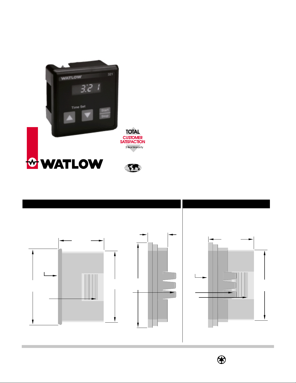
Dimensions
Figure 1a – Series 321 Timer and mounting collar, side view.
.750"
(19.1mm)
Front Panel
2.85"
(72.4mm)
Ridges
1.750"
(44.5mm)
2.585"
(65.7mm)
3.325"
(85.46mm)
Tabs
321 Timer Mounting Collar Timer flush with Mounting Collar
Figure 1b – Series 321 Timer inserted
in the mounting collar, side view.
1.750"
(44.5mm)
Front Panel
2.585"
(65.7mm)
Tabs
Ridges
W321-XUMN Rev B Made in the U.S.A
May 1997 (1107) Printed on Recycled Paper
10% Postconsumer Waste
Page 2
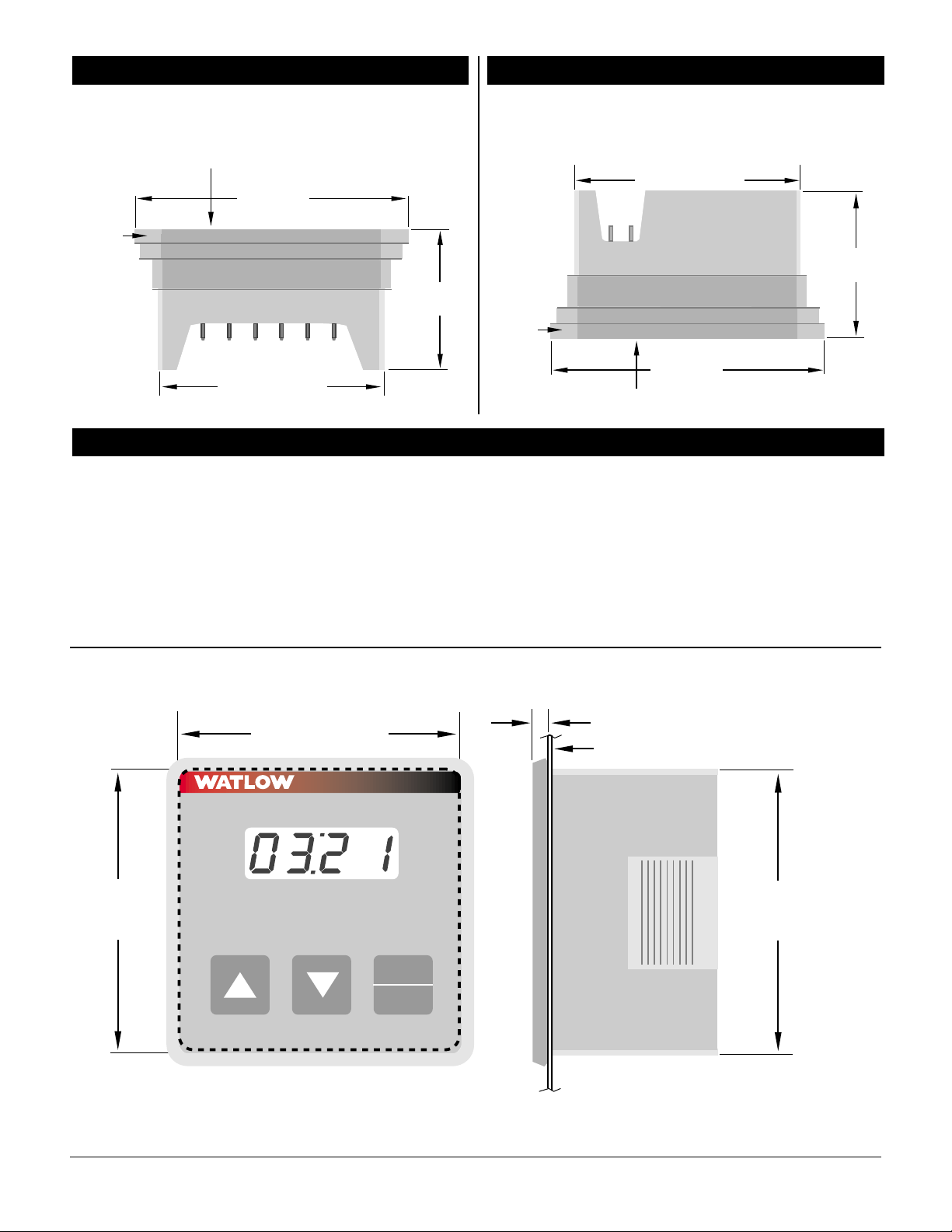
Dimensions Dimensions
Figure 2a – Series 321 Timer inserted
in the mounting collar, bottom view.
321 Timer Front Panel
3.325"
(85.46mm)
Mounting
Collar
1.750"
(44.5mm)
2.585" (65.7mm)
Installation
Through-the-Panel Installation Procedure:
1. Make a panel cutout using the dimensions in
Figure 2c.
2. Remove the timer from its collar and set the
collar aside.
3. Insert the timer into the cutout. Check to see
that the gasket is not twisted and is fully seated
in its channel.
Figure 2b – Series 321 Timer inserted
in the mounting collar, top view.
2.585" (65.7mm)
1.750"
(44.5mm)
Mounting
Collar
3.325"
(85.46mm)
321 Timer Front Panel
4. While pressing the front of the timer against the
panel, slide the mounting collar over the back of
it. The tabs on the collar must line up with the
ridges on the timer for secure installation - see
Figure 1b.
5. The tabs on each side of the collar have teeth
that latch into the ridges of the timer. Be sure
to apply enough pressure to firmly install the
timer.
Figure 2c – Series 321 Through-the-Panel dimensions.
2.585" (65.7mm)
321
2.585"
(65.7mm)
Time Set
Start
Stop
.250" (6.35mm)
Panel
2.585" Square Cut
(65.7mm)
WATLOW Series 321 User's Manual 2
Page 3

Installation
Flush-Mount Installation Procedure:
1. Make the display and three-key panel cutouts
using the dimensions in Figure 3a.
2. Drill four of the eight labeled holes to allow for a
#6 stud. You must use a combination of the
holes labeled 1, 3, 5, and 7 or the holes labeled
2, 4, 6, and 8.
3. Press the mounting studs through the front of
the holes prior to installing your decal/overlay.
(NOTE: Decal/overlay is not supplied by Watlow.
Figure 3a – Series 321 Flush Mount dimensions.
4. Remove the timer from the collar.
5. Remove the gasket and discard, then firmly
reinsert the timer into the collar. The tabs on
the timer must lock into the ridges on the
collar — see Figure 1b.
6. Attach timer/collar to the panel by installing
and tightening the nuts on the mounting
studs.
3.175" Typ. (2)
(80.6mm)
3.175"
(80.6mm)
Typ. (2)
.838"
(21.3mm)
Typ. (2)
1.50"
(38.0mm)
Typ. (2)
.838"
(21.3mm)
Typ. (2)
8
7
1.50" Typ. (2)
(38.0mm)
1
C
L
.750"
(19.1mm)
Start
Stop
2
3
C
L
Of Display
.288" (7.32mm)
1.125"
(28.58mm)
4
.175" (4.44mm)
6
.750"
(19.1mm)
(38.0mm)
C
L
1.5"
5
Diameter .550" Typ. (3)
(14.0mm)
WATLOW Series 321 User's Manual 3
Page 4

Wiring
Wiring
Power Wiring
Voltage Input: 120V~ (ac), nominal.
Figure 4a –
Series 321
back view.
L1
L2
AC
Ó
WARNING:
Possibility of
shock. There
is no isolation.
Fuse
Output 1 Wiring
Figure 4b –
Series 321
back view.
L1
AC
L1 L2
L1
AC
L2
C
CNOC
L1
L2
AC
L2
C
CNO
CNOC
1
1
1
Interlock Wiring
Figure 4d –
IL
NO
2
NO
C
1
NO
2
Series 321
back view.
ç
NOTE: The Interlock
must be closed for the
timer to initiate a
timing sequence.
IL
IL
IL
CNOC
NO
L1
L2
1
2
AC
ç
NOTE: The switch and
wiring practices used
for interlock operations
must meet U.L. Standards.
Displays
IL
NO
2
NO
C
1
NO
2
• Point ➀ is flashing:
Interlock is in an open condition, see
Figure 4e.
• Points ② and ➂ are not illuminated:
Timer is in a Hold/Ready condition, see
Figure 4e.
• Points ② and ➂ are illuminated:
Timer is running, see Figure 4e.
• Numeric Display is illuminated:
The Numeric Display is always active
when power is applied to the timer, see
Figure 4e.
Output 2 Wiring
Figure 4c –
Series 321
back view.
L1
AC
L2
Figure 4e – Series 321 front display.
IL
321
➁
CNOC
NO
L1
L2
1
2
AC
C
NO
C
1
NO
2
CNO
2
➀
➂
Time Set
Start
Stop
WATLOW Series 321 User's Manual 4
Page 5

Operation
Memory Operation
Power On
Apply power to the Series 321 — see Figure 4a.
The numeric display is always active when power is
applied to the timer.
Increase Time
Pressing this key increases the countdown time. If
the Increase Time button is pressed when the
maximum time, 9959, is displayed, the unit will
wrap to the minimum number, 000, and continue
increasing.
Decrease Time
This key is used to decrease the countdown time.
If the Decrease Time button is pressed when the
minimum time, 000, is displayed, the unit will
wrap to the maximum number, 9959, and continue
decreasing.
NOTE: Actuation of the Increase or Decrease keys
ç
will not be recognized when a countdown sequence is in progress.
Start
Start/Stop
This key is used to start and stop the countdown
sequence, enter a countdown time into memory,
recall a countdown time from memory, and
deactivate Relay 1 or Relay 2.
• Pressing this key when a countdown sequence is
in progress will cause the timer countdown to stop
and Relay 1 to de-energize. The unit will then go
into the Hold/Ready condition.
• Pressing this key when a countdown time greater
than 0 is selected and the timer is in a Hold/
Ready condition will cause Relay 1 to energize
and the timer to begin counting down in one
second intervals.
• Pressing this key while Relay 2 is energized after
completing a countdown sequence will cause
Relay 2 to de-energize prior to the 30 second time
out. Relay 2 will remain de-energized until next
countdown sequence is completed.
Stop
Memory Feature
The memory feature is always active.
Storing — Every time the countdown sequence is
initiated, the beginning countdown time, as shown
in the display, will be stored in memory. This will
replace any previously stored countdown time.
Recalling — The time stored in the memory is
recalled by pressing the Start/Stop key while a
countdown sequence is not in process and the
display is at 000. The time recalled from the
memory will be shown on the display.
Modifying — Once the recalled time is shown on
the display and the countdown sequence has not
begun, it can be modified using the Increase or
Decrease Time keys. If you modify the recalled
time it will replace the stored time when the Start/
Stop key is pressed.
Using — When the timer is in the Hold/Ready
state and the memory time or the modified memory
time is displayed, pressing the Start/Stop key will
begin the countdown sequence.
Troubleshooting
• Display is not illuminated:
Check for proper power wiring – see Figure 4a.
• Upper left decimal point is flashing:
Interlock condition has opened during a countdown sequence – see Figure 4e.
• Timer will not initiate a countdown:
Interlock has opened.
• Other:
Check all wiring connections – see Page 2,
Contact your Watlow Sales Agent,
Contact us;
Phone: 507-454-5300
Fax: 507-452-4507
For technical support, ask for an Applications
Engineer. To place an order, ask for customer
service. To discuss a custom option ask for a
Series 321 Product Manager.
Removing the Series 321
Through-the-Panel Mount Removal:
1. To remove the Series 321, you must first remove
the mounting collar.
2. To remove the mounting collar, slide a thin tool,
such as a putty knife, between all three mounting tabs and the ridges on both sides of the
Timer at once — see Figure 1b.
3. While lifting the tabs, push on the back of the
Timer and slide it out of the mounting collar.
Flush-Mount Removal:
1. Remove the four nuts on the mounting studs
that you previously installed to attach the
Timer to the panel.
2. Remove the Timer and mounting collar from the
panel.
3. Then follow the "Through-the-Panel Mount
Removal" procedure for removing the mounting
collar.
WATLOW Series 321 User's Manual 5
Page 6

Specifications Ordering Information
Installation
(1015) (1016)
Control Mode
• Countdown timer: hours/minutes, minutes/
seconds
• Timer output modes: Output 1 energized during
countdown only, Output 2 energized at completion
Custom / Standard
3 2 1 = Standard
XXX = Customer Special
of countdown for a period of 30 seconds
Operator Interface
• Single, four digit (seven segment) display, red
• Three tactile feedback momentary contact or push
Maximum Countdown Time
M = 99 Minutes (Minutes/Seconds Displayed)
H = 8:59 (Hours/Minutes Displayed)
button switches
Outputs, Dual
• #1: Mechanical relay form A 6A @ 120V~ (ac),
3A @ 240V~ (ac) no RC contact suppression
• #2: Mechanical relay form A 6A @ 120V~ (ac),
3A @ 240V~ (ac) no RC contact suppression
Safety Interlock
• Dry contact closure, minimum switch open resistance: 1M ohm, maximum switch closed resistance: 500 ohms
#1 Output
D = Electromechanical Relay, NO SPST,
6A @ 120V~ (ac), 3A @ 240V~ (ac)
#2 Output
D = Electromechanical Relay, NO SPST,
6A @ 120V~ (ac), 3A @ 240V~ (ac)
Line V oltage
1 = 120V~ (ac), 60 Hz
Timer Accuracy
• + 0.1% of programmed time
• Timer resolution 1 second
Mounting Style
0 = Universal Panel Flush-Mount
Agency Approvals
• UL 917
• C-UL
Power
• 108 to 132V~ (ac), 57 to 63 Hz
Mechanical
• Square 1/8 DIN panel-mount or behind the panel
Overlay / Software
00 = Standard Watlow Identification
01 = No Overlay
XX = Custom Overlays, parameters or software, Consult Factory
Display
R = Red Display Color
flush-mount
• Width x height x depth = 2.677” x 2.677” x 1.50”
(68mm x 68mm x 37.5mm)
Operating Environment
• 0 to 60°C / 32 to 140°F
• 0 to 90% RH non-condensing
Recycling
To assure proper disposal, Watlow accepts used
321s. Phone (507) 454-5300 for Return Materials
Authorization (RMA) number. Contact your
Watlow representative for details.
T X X X - D D 1 - 0 X X R
Returns
1. Call Customer Service: 507-454-5300, or fax:
507-452-4507, for a Return Material
Authorization (RMA) number before returning
any item for repair.
2. Make sure the RMA number is on the outside of
the carton and on all paperwork returned. Ship
on a freight prepaid basis.
3. A restocking charge of 20% of the net price
applies for all stock controls and accessories
returned in like-new condition and within 120
days after shipment. Non-stock and modified
stock items are not returnable.
4. If the unit is unrepairable, it will be returned to
you with a letter of explanation. Repair costs
will not exceed 50% of the original cost.
Warranty
The Series 321 is warranted to be free of defects in
material and workmanship for 36 months after
delivery to the first purchaser for use, providing
that the unit has not been misapplied. Because
Watlow has no control over its use or misuse, we
cannot guarantee against failure. Watlow's obligations hereunder, at Watlow's option, are limited to
replacement or refund of the purchase price of a
unit that upon examination proves to be defective
within the warranty period. This warranty does
not apply to damage resulting from transportation,
alteration, misuse or abuse.
WATLOW Series 321 User's Manual 6
 Loading...