

Watlow 104 User Manual
Series 104
User ’s Manual
On-off Temperature
Controller
1241 Bundy Boulevard, P.O. Box 5580, Winona, Minnesota USA 55987-5580
Phone: +1 (507) 454-5300, Fax:+1 (507) 452-4507, Internet: http://www.watlow.com
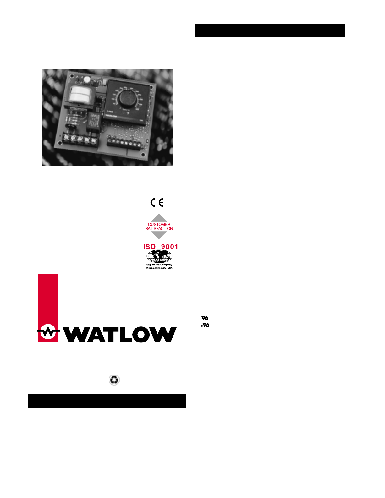
Watlow’s Series 104 is an economical open board, on-off
temperature controller with a thermocouple or RTD sensor
input. Installation and setup of the control is simple and
easy.
The Series 104 offers setpot options including integral
or fixed set point. Factory selectable options include electromechanical relay, SSR or switched dc output, dual scale,
and heat or cool control mode.
(1922)
Control Mode
• On-off
• Nominal switching hysteresis, typically 3°F (1.7°C)
Operator Interface
• LED indication of output status
• Dial scale calibrated to compensate for sensor non-linearities
• Integral set point
• Dual temperature scale (°F and °C)
• Fixed set point
• Manufactured to specified value
Input
• Thermocouple or platinum RTD available
• Thermocouple with automatic cold junction compensation
• Thermocouple may be isolated or grounded
• Thermocouple and RTD break protection de-energizes output
• 2- or 3-wire RTD input, 100Ω, 500Ω or 1000Ω @ 0°C calibrated for
0.003850Ω/Ω °C curve, factory selectable
Output
• Solid-state relay, Form A, 0.5A @ 24V~ min., 264V~ maximum,
opto-isolated, zero cross switching
• Switched dc signal provides a non-isolated minimum turn-on voltage
of 3VÎ (dc) into a minimum 500Ω load, maximum on voltage not
greater than 32VÎ (dc)
• Electromechanical relay, 8A, Form C, SPDT: 8A @ 240V~ resistive,
8A, 28VÎ (dc) resistive, 240V~ 275 VApilot duty rated
Accuracy
Adjustable Set Point
• Calibration accuracy: ±1% of span, at 77°F ±5°F (25°C ± 3°C)
ambient and rated line voltage ± 1%
• Set point accuracy: ±3% of dial scale
• Accuracy span: 1000°F (540°C) minimum
Fixed Set Point
• Calibration accuracy: ±10°F/±6°C of setting, at 77°F ±5°F (25°C
±3°C) ambient and rated line voltage ±1%
Temperature Stability
• Thermocouple: Typically 5µV/°F ambient (9µV/°C ambient) input
referenced
• RTD: Typically 0.2°F/°F ambient (0.2°C/°C ambient)
Voltage Stability
• ±0.01% of span (min span of 1000°F or 540°C) per % of rated line
voltage
Agency Approvals
• CE: EN61010 - Safety
EN61326 - Industrial Immunity, Class B Emissions
Installation Category 2, Pollution Degree 2
• 873 Recognized, File #E43684
• Recognized to C22.2 No. 24, File #E43684
• Approved for use in commercial cooking applications
Terminals
• Sensor input
• Screw clamp terminal: 12-26 gauge wire
• Power input and control output
• #6 screws on barrier strip
Power
• 120V~, +10%/-15%, 50/60 Hz
• 230V~ to 240~, +10%/-15%, 50/60 Hz
• 10VAmaximum power
Operating Environment
• 32 to 131°F (0 to 55°C)
• 0 to 90% RH, non-condensing
• Storage temperature: -4 to 185°F (-20 to 85°C)
Dimensions
• Width: 4.5 in (114 mm)
• Length: 4.0 in (102 mm)
• Depth: 1.5 in (38 mm)
Weight
• 0.7 lb (0.3kg)
UL®is a registered trademark of Underwriter’s Laboratories, Inc.
Note: Specifications subject to change without notice.
Specifications
General Description
$5.00 Made in the U.S.A.
Printed on Recycled Paper
10% Postconsumer Waste
0600-0004-0008 Rev C
August 2000
Supersedes: 0600-0004-0008 Rev B
TOT AL
3 Y ear Warranty

Figure 3a — Series 104 dimensions.
Use the following procedure to mount and install the
Watlow Series 104 temperature control.
1. Locate and drill four 0.156 in (4 mm) holes in the desired
panel location. See Figure 2a for hole locations.
2. Mount the Series 104 using four #6 screws.
3. Connect the sensor, load, and power as illustrated in the
wiring diagrams on pages 3 and 4. See the wiring
diagrams.
• Use the correct sensor type per the model number on the
unit sticker.
• Use the proper thermocouple or RTD polarity.
• Insulate the thermocouple mounting from the mounting
surface to prevent heat migration input errors.
• Thermocouple leads should be twisted pair wire and
routed separately from any other high voltage lines.
• In electrically noisy environments (heavy switching of
contactor, motors, solenoids, etc.) use shielded thermocouple lead wire with the shield connected at the sensor
end only.
• All wiring and fusing must conform to the National
Electric Code (NEC) NFPA70 and any other locally
applicable codes.
• Fuse the independent load voltage on the L1 (hot) side
and connect it to the common (COM) side of the relay.
• Long lead lengths create electrical resistance. When using
a two-wire RTD, there will be an additional input error
for every 1Ω of lead length resistance. That resistance
when added to the resistance of the RTD element, can
result in erroneous input to the temperature control. To
overcome this problem, use a three-wire RTD sensor,
which compensates for lead length resistance. When
extension wire is used for a three-wire RTD, all three
extension wires must have the same electrical resistance
(i.e. same gauge, copper stranded).
Note, caution and warning symbols appear throughout this
book to draw your attention to important operational and
safety information.
A “NOTE” marks a short message to alert you to an
important detail.
A “CAUTION” safety alert appears with information that is
important for protecting your equipment and performance.
A “WARNING” safety alert appears with information that is
important for protecting you, others and equipment from
damage. Pay very close attention to all warnings that apply
to your application.
The ç symbol (an exclamation point in a triangle) precedes
a general CAUTION or WARNING statement.
The Ó symbol (a lightning bolt in a triangle) precedes an
electric shock hazard CAUTION or WARNING safety
statement.
120VÅ 104 _ - 1 _ _ _ - 0000
230 to 240VÅ 104 _ - 2 _ _ _ - 0000
NOTE: The line voltage is specified by your model number.
Figure 3b — Power wiring.
Ó
WARNING: To avoid potential electric shock, use National Electrical
Code (NEC) safety practices when wiring and connecting this unit to
a power source and to electrical sensors or peripheral devices.
Failure to do so could result in injury or death.
All wiring and fusing must conform to the National Electric
Code and to any locally applicable codes.
ç
CAUTION: Applying incorrect line voltage may result in irreversible
damage to the controller.
Power Wiring
Safety Information
Wiring Guidelines
Installation
)
Dimensions
2 ■ Watlow Series 104 User’s Manual
200
150
100
50
00
4.0 in (102 mm)
4.5 in (114 mm)
4.500"
250
300
350
400
450
500
3.5 in
(89 mm)
(102 mm
4.0 in
250
300
200
350
400
450
500
Fuse
L1 L2
150
100
50
00
Recommended fuse size: 1A
4.500"
 Loading...