

Watlow 103 User Manual
1 ■ Watlow Series 103 User’s Manual
(2001)
Control Mode
• On-off
• Nominal switching hysteresis, typically 3°F (1.7°C)
Operator Interface
• LED indication of output status
• Dial scale calibrated to compensate for sensor non-linearities
• Integral set point
• Dual temperature scale (°F and °C)
• Fixed set point
• Manufactured to specified value
Input
• Thermocouple or platinum RTD available
• Thermocouple with automatic cold junction compensation
• Thermocouple may be isolated or grounded
• Thermocouple and RTD break protection de-energizes output
• 2- or 3-wire RTD input, 100Ω, 500Ω or 1000Ω @ 0°C calibrated
for 0.003850Ω/Ω °C curve, factory selectable
Output
• Solid-state relay, Form A, 0.5A @ 24V~ min., 264V~ maximum,
opto-isolated, zero cross switching
• Switched dc signal provides a non-isolated minimum turn-on voltage of 3VÎ (dc) into a minimum 500Ω load, maximum on voltage
not greater than 32VÎ (dc)
• Electromechanical relay, 8A, Form C, SPDT: 8A@ 240V~ resistive, 8A, 28VÎ (dc) resistive, 275 VA pilot duty rated
Accuracy
Adjustable Set Point
• Calibration accuracy: ±1% of span, at 77°F ±5°F (25°C ± 3°C)
ambient and rated line voltage ± 1%
• Set point accuracy: ±3% of dial scale
• Accuracy span: 1000°F (540°C) minimum
Fixed Set Point
• Calibration accuracy: ±10°F/±6°C of setting, at 77°F ±5°F (25°C
±3°C) ambient and rated line voltage ±1%
Temperature Stability
• Thermocouple: Typically 5µV/°F ambient (9µV/°C ambient) input
referenced
• RTD: Typically 0.2°F/°F ambient (0.2°C/°C ambient)
Voltage Stability
• ±0.01% of span (min span of 1000°F or 540°C) per % of rated
line voltage
Agency Approvals
• CE: EN61010 - Safety
EN61326 - Industrial Immunity, Class B Emissions
Installation Category 2, Pollution Degree 2
• 873, File #E43684
• to C22.2 No. 24, File #E43684
• Approved for use in commercial cooking applications
Terminals
• Captive screw, cage clamp connection, 0.155 in. (4mm) max.
width screwdriver blade, 30 to 14-gauge wire
Mounting
• DIN rail, DIN EN50022, 35mm x 7.5mm
• Sub-panel mounting
Power
• 120V~, +10%/-15%, 50/60 Hz
• 230V~ to 240~, +10%/-15%, 50/60 Hz
• 10VAmaximum power
Operating Environment
• 32 to 131°F (0 to 55°C)
• 0 to 90% RH, non-condensing
• Storage temperature: -4 to 185°F (-20 to 85°C)
Dimensions
• Width: 2.28 in (60 mm)
• Height: 4.45 in (115mm)
• Depth: 3.89 in (100 mm)
Weight
• 0.7 lb. (0.3kg)
UL®is a registered trademark of Underwriter’s Laboratories,Inc.
Note: Specifications subject to change without notice.
Specifications
Series 103
User’s Manual
On/Off T emperature
Controller
1241 Bundy Boulevard, P.O. Box 5580, Winona, Minnesota USA 55987-5580
Phone: +1 (507) 454-5300, Fax: +1 (507) 452-4507, Internet: http://www.watlow.com
0600-0004-0007 Rev D
January 2001
Supersedes: 0600-0004-0007 Rev C
$5.00 Made in the U.S.A.
Printed on Recycled Paper
10% Postconsumer Waste
The Watlow Series 103 is a DIN rail mount, on-off
temperature controller with a thermocouple or RTD
sensor input. The DIN rail mounting offers quick and
easy installation with the use of simple hand tools.The
controller may also be flush mounted.
The Series 103 can be factory configured as either a
heat or cool output. Output types include electromechanical relay, solid-state relay or open collector output.
The Series 103 has an LED for output status
indication and can be ordered with an integral, adjustable
set point or a fixed set point.
General Description
TOT AL
CUSTOM ER
SATISFACTION
3 Y ear Warranty
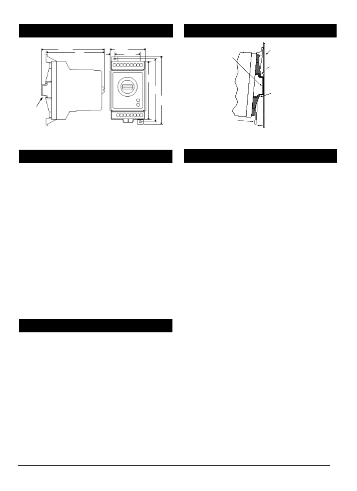
Figure 2a — Series 103 dimensions.
Sub-Panel Mounting the Series 103
1.Using the controller as a location template, mark both
mounting holes.
2.Drill two 0.19 in. (5mm) diameter holes in the desired
panel location. See Figure 2a for hole locations.
3.Mount the Series 103 using two #8-32 screws.
DIN Rail Mounting the Series 103
1.Place the Series 103 upper mounting clip on the top edge
of the DIN rail. See the Figure 2b on this page.
2.Press down firmly on the top front edge of the Series 103.
The control “snaps” securely onto the rail. If the control
does not snap on, check to see if the DIN rail is bent.
Minimum clipping distance is 1.37 in. (34.8mm), the
maximum is 1.39 in. (35.3mm).
Removing the Series 103 from the DIN Rail
1.Place your fingers on the release lever located at the base
of the Series 103.
2.While gently pressing on the top of the case, above
Terminals 1 to 9, pull forward on the release lever.
Note, caution and warning symbols appear throughout this
book to draw your attention to important operational and
safety information.
A “NOTE” marks a short message to alert you to an important detail.
A “CAUTION” safety alert appears with information that is
important for protecting your equipment and performance.
A “WARNING” safety alert appears with information that is
important for protecting you, others and equipment from
damage. Pay very close attention to all warnings that apply
to your application.
The ç symbol (an exclamation point in a triangle) precedes
a general CAUTION or WARNING statement.
The Ó symbol (a lightning bolt in a triangle) precedes an
electric shock hazard CAUTION or WARNING safety
statement.
Figure 2b — Series 103 side view mounting.
• Use the correct sensor type per the model number on the
unit sticker.
• Use the proper thermocouple or RTD polarity.
• Insulate the thermocouple mounting from the mounting
surface to prevent heat migration input errors.
• Thermocouple leads should be twisted pair wire and
routed separately from any other lines.
• In electrically noisy environments (heavy switching of
contactor, motors, solenoids, etc.) use shielded thermocouple lead wire with the shield connected at the sensor end
only.
• All wiring and fusing must conform to the National
Electric Code (NEC) NFPA70 and any other locally applicable codes.
• Fuse the independent load voltage on the L1 (hot) side
and connect it to the common (COM) side of the relay.
ç
CAUTION: A power disconnect switch located near the controller
is recommended to shut down power in case of controller
failure.
• Long lead lengths create electrical resistance. When using
a two-wire RTD, there will be an additional error for
every 1Ω of lead length resistance. That resistance when
added to the resistance of the RTD element, can result in
erroneous input to the temperature controller. To overcome this problem, use a three-wire RTD sensor, which
compensates for lead length resistance. When extension
wire is used for a three-wire RTD, all three extension
wires must have the same electrical resistance (i.e. same
gauge, copper stranded).
Wiring Guidelines
Mounting
Safety Information
Installation
Dimensions
2 ■ Watlow Series 103 User’s Manual
2.28 in.
(58mm)
1.62 in.
(41mm)
3.75 in.
(96mm)
4.10 in.
(104mm)
4.45 in.
(113mm)
35mm x 7.5mm
Rail is not
included in
the assembly
3.89 in.
(99mm)
3.72 in.
(95mm)
Panel
DIN Rail
Upper Mounting Clip
Lower Mounting Clip
Release Lever
Snap Action
 Loading...