

Watlow 102 User Manual
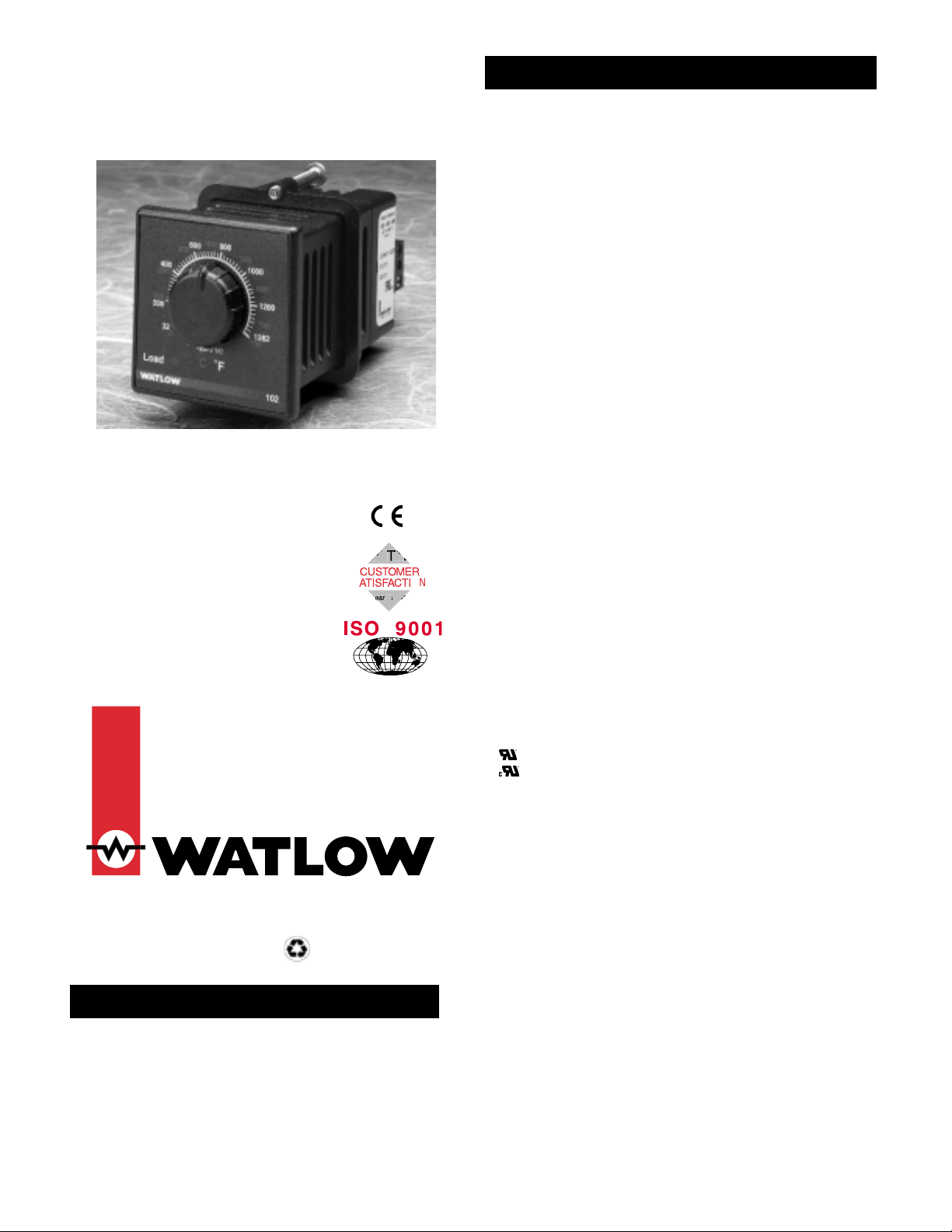
Series 102
User ’s Manual
On-off Temperature
Controller
1241 Bundy Boulevard, P.O. Box 5580, Winona, Minnesota USA 55987-5580
Phone: +1 (507) 454-5300, Fax: +1 (507) 452-4507, Internet: http://www.watlow.com
The Watlow Series 102 is a 1/16 DIN, on-off
temperature controller with a thermocouple or RTD sensor
input.
The compact size of the controller allows more flexibility
in applications where space is a problem. The Series 102 has
a standard integral setpot and front panel LED output
status indicator.
(1915)
Control Mode
• On-off
• Nominal switching hysteresis, typically 3°F (1.7°C)
Operator Interface
• Sealed membrane front panel
• LED indication of output status
• Dial scale calibrated to compensate for sensor non-linearities
• Integral set point
• Dual temperature scale (°F and °C)
Input
• Thermocouple or platinum RTD available
• Thermocouple with automatic cold junction compensation
• Thermocouple may be isolated or grounded
• Thermocouple and RTD break protection de-energizes output
• 2- or 3-wire RTD input, 100Ω, 500Ω or 1000Ω @ 0°C calibrated for
0.003850Ω/Ω °C curve, factory selectable
Output
• Electromechanical relay, 3A, Form C, SPDT: 3A @ 240VÅ, 3A @
28VÎ (dc), resistive, 240V~ 275 VA pilot duty rated
• Solid-state relay, Form A, 0.5A @ 24VÅ min., 264VÅ max., optoisolated, zero cross switching
• Switched dc configuration; switched dc supply voltage 3 to 32VÎ
(dc) into a minimum 500Ω load
Accuracy
Adjustable Set Point
• Calibration accuracy: ±1% of span, at 77°F ±5°F (25°C ± 3°C)
ambient and rated line voltage ± 1%
• Set point accuracy: ±3% of dial scale
• Accuracy span: 1000°F (540°C) minimum
Fixed Set Point
• Calibration accuracy: ±10°F/±6°C of setting, at 77°F ±5°F (25°C
±3°C) ambient and rated line voltage ±1%
Temperature Stability
• Thermocouple: Typically 5µV/°F ambient (9µV/°C ambient) input
referenced
• RTD: Typically 0.2°F/°F ambient (0.2°C/°C ambient)
Voltage Stability
• ±0.01% of span (min span of 1000°F or 540°C) per % of rated line
voltage
Agency Approvals
• CE: EN61010 - Safety
EN61326 - Industrial Immunity, Class B Emissions
Installation Category 2, Pollution Degree 2
• 873, File #E43684
• to C22.2 No. 24, File #E43684
• Approved for use in commercial cooking applications
Terminals
• Screw clamp terminal: 12- to 26-gauge wire
Power
• 120V~, +10%/-15%, 50/60 Hz
• 230V~ to 240~, +10%/-15%, 50/60 Hz
• 10VAmaximum power
Operating Environment
• 32 to 131°F (0 to 55°C)
• 0 to 90% RH, non-condensing
• Storage temperature: -4 to 185°F (-20 to 85°C)
Dimensions
• Height: 2.1 in (55 mm)
• Width: 2.1 in (55 mm)
• Depth: 4.0 in (102 mm)
• Behind panel: 3.50 in (89 mm)
• Front panel: 0.5 in (13 mm)
Weight
• 0.7 lb (0.3kg)
UL®is a registered trademark of Underwriter’s Laboratories, Inc.
Note: Specifications subject to change without notice.
Specifications
General Description
$5.00 Made in the U.S.A.
Printed on Recycled Paper
10% Postconsumer Waste
0600-0004-0006 Rev C
August 2000
Supersedes: 0600-0036-0002 Rev B
O
3
arran
ran
S
O
arranty
Registered Company
Winona, Minnesota USA
Watlow Series 102 User’s Manual ■2
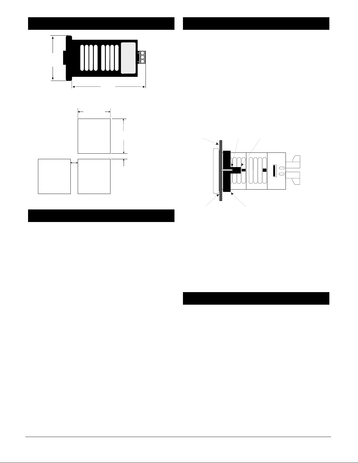
Figure 2a — Series 102 dimensions.
Figure 2b — Panel cutout and spacing.
• Use the correct sensor type per the model number on the
unit sticker.
• Use the proper thermocouple or RTD polarity.
• Insulate the thermocouple mounting from the mounting
surface to prevent heat migration input errors.
• Thermocouple leads should be twisted pair wire and
routed separately from any other high voltage lines.
• In electrically noisy environments (heavy switching of
contactor, motors, solenoids, etc.) use shielded thermocouple lead wire with the shield connected at the sensor
end only.
• All wiring and fusing must conform to the National
Electric Code (NEC) NFPA70 and any other locally
applicable codes.
• Fuse the independent load voltage on the L1 (hot) side
and connect it to the common (COM) side of the relay.
ç
CAUTION: A power disconnect switch located near the controller
is recommended to shut down power in case of controller
failure.
• Long lead lengths create electrical resistance. When using
a two-wire RTD, there will be an additional error for
every 1Ω of lead length resistance. That resistance when
added to the resistance of the RTD element, can result in
erroneous input to the temperature controller. To overcome this problem, use a three-wire RTD sensor, which
compensates for lead length resistance. When extension
wire is used for a three-wire RTD, all three extension
wires must have the same electrical resistance (i.e. same
gauge, copper stranded).
To Mount the Series 102
1. Make a panel cutout, using the dimensions in Figure 2b.
2. Check to see that the external case gasket of the Series
102 is facing the panel surface. Insure that the gasket is
not twisted and is seated within the case bezel flush with
the bezel. Insert the Series 102 into the cutout.
3. Slide the mounting collar over the back of the controller.
The two tabs of the mounting collar will fit into one of the
vent openings of the case.
4. While pressing the front of the case firmly against the
panel, tighten the two #8-32 screws until tight. Make sure
you cannot move the case within the cutout.
Figure 2c — Mounting.
To Remove the Series 102
1. Remove the Series 102 by loosening the mounting screws
located on the mounting collar.
2. Using the screws, gently pry them away from the case.
This will lift the mounting tabs, allowing the collar to
slide backwards.
NOTE: Make sure the rounded side of the D-shaped external case
gasket faces the panel surface and the gasket is fully seated.
Note, caution and warning symbols appear throughout this
book to draw your attention to important operational and
safety information.
A “NOTE” marks a short message to alert you to an
important detail.
A “CAUTION” safety alert appears with information that is
important for protecting your equipment and performance.
A “WARNING” safety alert appears with information that is
important for protecting you, others and equipment from
damage. Pay very close attention to all warnings that apply
to your application.
The ç symbol (an exclamation point in a triangle) precedes
a general CAUTION or WARNING statement.
The Ó symbol (a lightning bolt in a lightning bolt in a
triangle) precedes an electric shock hazard CAUTION or
WARNING safety statement.
Safety Information
Installation
Wiring Guidelines
Dimensions
2.1 in
(55 mm)
square
4.0 in
(102 mm)
1.77 to 1.79 in
(45.0 to 45.5 mm)
Panel Cutout
0.85 in
(20 mm)
Your Panel
Thickness
0.06 to 0.38 in
(1.5 to 9.7 mm)
(45.0 to 45.5 mm)
1.77 to 1.79 in
0.38 in
(9.7 mm)
minimum
Panel
Screw
Mounting Tab
External Gasket
Mounting Collar
 Loading...