

Page 1

W aters 2690
Separations Modul e
Quick Star t Guid e
34 Maple Street
Milford, MA 01757
WAT553-03TP, Revision 3
Page 2

NOTICE
The information in this document is subject to change without notice and should not be
construed as a commitment by Waters Corporation. Waters Corporation assumes no
responsibility for any errors that may appear in this document. This manual is believed to
be complete and accurate at the time of publication. In no event shall Waters Corporation
be liable for incidental or consequential damages in connection with, or arising from, the
use of this manual.
© 1996, 1998, 2000 WATERS CORPORAT ION. PRINTED IN THE UNITED STATES OF
AMERICA. ALL RIG H TS RESERVED. THIS BO OK OR PARTS THERE OF MAY NOT BE
REPRODUCED IN ANY FORM WITHOUT THE WRITTEN PERMISSION OF THE
PUBLISHER.
Alliance , M il len n iu m, an d Waters are t r ad emar k s o f Waters Corpor at io n .
All other trad em a rk s a re the sol e p r op er ty of thei r re s pe ctive owners.
Page 3
Quick Summary
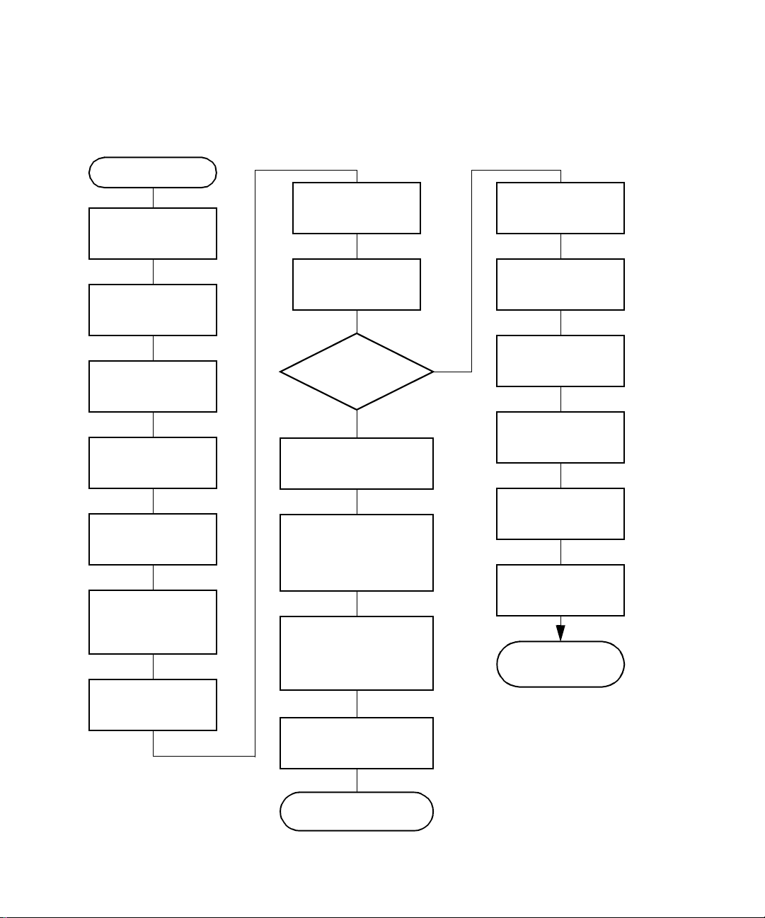
The figure below summarizes the information contained in this Quick Start Guide. Use it
as a reference after you have read the entire document.
Start
Power on the
Separations
Module
Configure the
Separations
Module
Degas or
Sparge Eluents
Prime the Solvent
Management
System
Prime the Plunger
Seal Wash Pump
(If Insta lle d )
Purge the Sample
Management
System
Prime the Needle
Was h Pum p
Adjust the
Seal Pack
Load the
Carousels
Perform
an Automatic
Run?
Yes
Press the
Samples
on the Main Screen
Select the Separation
Method, Sample Set , or
Template to Run, then
Press
Enter Data Required by
the Separation Method,
Sample Template
Press the
Screen Key to Start
Screen Key
Screen Key
Run
Sample Set, or
the Run
Run
Routine
No
Set Flow Rate and
Composition
Set Sparge Rate
(if Applicable)
Set Control
Switches
Direct
Press
Function
Screen Key
Select Direct
Function to Perform
Enter Function
Parameters
The Function
Begins to Run
The Run Ends as
Programmed
Page 4

Conventions Used in This Guide
This Quick Start Guide uses the following conventions:
• Bold text indicates user input or action. For example, press
• When you are instructed to “press the X key”, pre ss the indica ted keypad k ey.
• When you are instructed to “press the X screen key,” press the keypad key directly
below the key name displayed on the screen.
Notes and Warnings
This guide uses the following note and warning conventions:
• Notes call out information that is important to the operator. For example:
Record your result before you proceed to the next step.
Note:
• Attentions provide information about preventing possible damage to the system or
equipment. For example:
Enter
.
STOP
Attention:
cell window.
• Cautions provide information essential to the safety of the operator. For example:
Caution:
laboratory practices when you operate your system.
Caution:
cord from the rear panel of the instrument before you perform the
procedures in this section.
To avoid damaging the detector flow cell, do not touch the flow
To avoid chemical or electrical hazards, always observe safe
To avoid electrical shock and possible injury, remove the power
Page 5

1
Introduction
The
Waters 2690 Separations Module Quick Start Guide
features of the Waters 2690 Separations Module and describes how to make a run.
Who Should Use This Guide?
This guide is intended for both novice and experienced chromatographers who need to
operate the Waters 2690 Separations Module.
What Is In This Guide?
The
Waters 2690 Separations Module Quick Start Guide
information to help you set up the Waters 2690 Separations Module and make a run. In
addition, this guide contains detailed flow charts that provide Waters-recommended steps
to prime, equilibrate, and purge both degasser and sparge-based 2690 Separations
Modules. Refer to Chapter 6,
This guide is not designed to teach you chemistry and does not contain background
Note:
or reference information.
Recommended Preparation Procedures .
introduces you to the basic
contains basic procedural
For additional information, or if you want to learn how to modify any of the procedures in
this guide, refer to the
With the purchase of the 2690 Separations Module, Waters supplies both this guide
Note:
and the Waters 2690 Separations Module Operator’s Guide in electronic format on a
CD-ROM. To install and view these guides on your computer, refer to the Readme file on
the CD-ROM. To purchase a printed version of the Operator’s Guide, contact W aters Sales
Support at 800-252-4752, extension 8101.
Waters 2690 Separations Module Operator’s Guide
.
Before You Begin
This guide assumes that:
• Your system is properly installed (refer to the
Operator’s Guide
• Your separation methods, sample sets, and/or sample templates are already
created and stored (refer to the
Chapter 6,
Creating Methods, Sample Sets, and Sample Templates).
, Chapter 2, Installing the Separations Module).
Waters 2690 Separations Module Operator’s Guide
Waters 2690 Separations Module
Introduction 5
,
Page 6

System Description
The Waters™ 2690 Separations Module (Figure 1-1) is an integrated solvent and sample
management platform. This integration of two traditional high performance liquid
chromatography (HPLC) components streamlines all critical separation functions.
Solvent Bot tle Tray
Detector Drip Tray
Fr ont P anel Displa y
and Keyboard
Floppy Disk Drive
Sample
Compartment
Access Door
Solvent Delivery
Tray Access Door
Syringe Access Door
Column Heater Module
Solvent Conditioning
Tray Access Door
TP01354
Figure 1-1 Waters 2690 XE Separations Module (Front View)
The sample management system in the Waters 2690 Separations Module uses five
carousels with a total capacity of 120 vials. A carrier rotates the carousels to the injection
station in the sample compart men t.
The Waters 2690 Separations Module is available from Waters in a number of
configurations, differing from each other by the options that are included.
The two primary configurations are designated:
2690
•
helium sparge for solvent conditioning, integral plunger seal-wash system, 120-vial
capacity sample management system, liquid-crystal display and keyboard user
interface, and floppy disk drive.
2690 XE
•
sparge system with a four-channel in-line vacuum degasser , and adds a column
heater and a sample heater/cooler.
6 Introduction
– Provides quaternary solvent, high-performance solvent delivery, integral
– Provides the capabilities of the 2690 base product, replaces the helium
Page 7

2 Preparing the Se parations Module for Operation
Before you can prepare the Separations Module for operation, you need to power on the
2690 Separations Module by moving the power switch (located at the top of the left side
panel) to the I (On) position. The startup diagnostics routine begins.
2.1 Powering On
Startup Diagnostics
The startup diagnos tics routine performs the following functions and tests:
• CPU board
• Memory (RAM and ROM)
• Keypad
•Display
• External communicat ion
• Digital signal processor (DSP)
• Floppy disk drive
Once the electronic part of the diagnostics test is complete, the front-panel screen
displays the results of the tests, as shown in Figure 2-1
STARTUP DIAGNOSTICS
CPU
ROM
RAM
KEYPAD
Figure 2-1 Diagnostic Test Results Screen
OK
OK
OK
OK
DISPLAY
DMA
GPIB
FLASH
OK
OK
OK
OK
Preparing the Separations Module for Operation 7
.
DSP
FLOPPY
CLOCK
OK
OK
OK
Page 8

The Main Screen
When the initial part of the start up diag nos tics routine is successful, the Main screen
appears in the front panel display (Figure 2-2
by initializing the:
• Needle, syringe, and valves
• Carousel carrier
• Solvent management system
The statuses of these mechanical diagnostics tests appear in the banner area of the Main
screen (Figure 2-2
not successful, refer to the
) while the diagnostics are running. If the startup diagnostics routine is
Waters 2690 Separations Module Operator’s Guide
8.5, Troubleshooting. When the startup diagnostics routine is complete, the Separations
Module enters the Idle mode.
Banner Area
Data Area
). The startup diagnostics routine cont inues
, Section
Screen Keys
Figure 2-2 Main Screen
8 Preparing the Separations Module for Ope ration
Page 9

2.2 Configuring the Separations Module
Before you can operate the Separations Module, you need to configure the Separations
Module for stand-alone or remote control and for a variety of other operating parameters.
No Interaction Mode
In this standalone mode, the Separations Module is not connected to the IEEE-488
interface bus. The Separations Module controls other non-IEEE devices in the HPLC
system using the I/O connections on the rear panel. Refer to the
Module Operator’s Guide
make I/O connections. Use this mode if you want to suspend communication with a
connected Millennium Chromatography Manager workstation and operate the Separations
Module and the other HPLC system components from their front panels.
To set the Separations Module to the No Interaction mode:
, Section 2.7.1, I/O Signal Connections, for the procedure to
Waters 2690 Separations
1. Press the
(Figure 2-3
2. Select the
3. Sel ect
4. Press
Config
No interaction
Exit
screen key in the Main screen. The Configuration screen appears
).
System
.
field, then press
, then press
Enter
Enter
to display a list of choices.
.
System Controller Mode
In this standalone mode, the Separations Module controls up to three detector channels
on the I EEE-488 b us. This can include two UV detector channels (Waters 2487 and/or 486
Tunable Absorbance Detectors) and one RI detector channel (Waters 2410 or 410
Differential Refractometer). You can also control other HPLC modules using the I/O
connections.
To set the Separations Module to the System Controller mode:
1. Press the
(Figure 2-3
Config
).
screen key in the Main screen. The Configuration screen appears
Preparing the Separations Module for Operation 9
Page 10

Figure 2-3 Configuration Screen
2. Select the
3. Sel ect
System Controller
4. Press the
System
field, then press
Detectors
, then press
screen key. A list of active devices (with their IEEE-488
Enter
to display a list of choices.
Enter
.
interface bus addresses) appears.
a. Press the
Scan
screen key to update the list.
b. P ress t he OK screen key to return to the Configuration screen.
5. Press
Exit.
The Separations Module is ready to control Waters detectors using
separation methods, sample sets, or sample templates.
Controlled by Millennium32 Mode
In this remote-control mode, a Millen nium Ch romat ography Manager work station r unning
Millenn iu m
system using the IEEE-488 interface bus.
To set the Separations Module to the Controlled by Millennium
1. S ele ct the
2. Select
3. Press
4. Select an address that is unused by other chromatographic components connected
5. Press
32
software (Windows 95, 98, or NT) controls the operation of your HPLC
32
mode:
System
field in the Configuration screen, then press
Enter
list of choices.
Controlled by Millennium
32
, then press
Enter
. The IEEE 488 Address
field is highlighted.
Enter
to display a list of addresses.
to the Millennium C hromatography Manager workstation, then press
Exit.
The Separations Module is ready to be controlled from the
Millennium Chromatography Manager workstation.
to display a
Enter
.
10 Preparing the Sepa rations Module for Operation
Page 11

Controlled by MassLynx Mode
In this remote-control mode, Micromass MassLynx NT software (Version 3.1 Build 004 or
higher) controls the 2690 Separations Module. MassLynx software is used with Micromass
mass spectrometry (MS) detectors, using the IEEE-488 interface between the Micromass
computer and the 2690 Separations Module.
To set the Separations Module to the Controlled by MassLynx mode:
1. S ele ct the
list of choices.
2. Select
is highlighted.
3. Press
4. Select an address that is unused by other chromatographic components connected
to the Micromass computer, then press
5. Press
computer.
System
Controlled by MassLynx
Enter
Exit.
The Separations Module i s r eady to be controlled from the M ass Lynx
field in the Configuration screen, then press
, then press
to display a list of addresses.
Enter
Enter
.
. The IEEE 488 Address field
Enter
to display a
Controlled by Millennium 2.xx Mode
In this remote-control mode, a Millen nium Ch romat ography Manager work station r unning
Millennium 2.xx soft ware (Wi ndows 3 .1) cont rols the oper ati on of y our HPLC syst em using
the IEEE-488 interface bus.
To set the Separations Module to the Controlled by Millennium 2.xx mode:
1. S ele ct the
list of choices.
2. Select
field is highlighted.
3. Press
System
Controlled by Millennium 2.xx
Enter
field in the Configuration screen, then press
, then press
to display a list of address pairs.
Ente r
Enter
to display a
. The IEEE 488 Address
4. Select an address pair that is unused by other chromatographic components
connected to the Millennium Chromatography Manager, then press
5. Press
The Separations Module appears as two devices in the Millennium System view:
•
•
Exit.
The Separations Module is ready to be controlled from the
Millennium Chromatography Manager workstation.
The solvent and sample manageme nt systems
The optional sample heater/cool er
– With an odd address.
Preparing the Separations Module for Operation 11
– With an even address.
Enter
.
Page 12

Refer to the
Automatic Runs Under Millennium Control, for details on making runs under Millennium
control.
Waters 2690 Separations Module Operator’s Guide
, Section 5.2, Making
Controlled by Operate Gradient by Event In
In the Operate Gradient by Event In mode, an external autosampler (a Waters 2700
Sample Manager, for example) signals the Solvent Management System of the
Separations Module to begin a gradient. In this mode, the Separations Module has no
can
control of IEEE-488 devices, however, the Separations Module
devices using the I/O connections on the rear panel.
To set the Separations Module to the Operate Gradient by Event In mode:
control non-IEEE
1. S ele ct the
list of choices.
2. Select
3. Press the
more detailed steps on defining Events In conditions, refer to the
Separations Module Operator’s Guide
Setting Configuration Parameters.
4. Set the Stop Flow field to the appropriate condition (
press
• Choose
• Choose
• Choose
5. Set the Hold 1 field to the appropriate condition (
• Choose
• Choose
System
Operate Gradient by Event In
Events In
Enter
not used.
Stop Flow I/O terminals of the Separations Module changes to a high (more
positive) TTL-level.
Flow I/O terminals of the Separations Module changes to a low (more negative)
TTL-level.
Hold 1 Inject terminals of the Separations Module changes to a high (more
positive) TTL-lev el to initiate a chromatographic run (and prevent an injection by
the Separations Module).
1 Inject terminals of the Separations Module changes to a low (more negative)
TTL-level to initiate a chromatographic run (and prevent an injection by the
Separations Module).
field in the Configuration screen, then press
, then press
screen key to display the Events In dialog box. If you need
Events In
,
.
Ignore
High
Low
High
Low
if the Stop Flow I/O terminals of the Separations Module are
if the output connection from the external autosampler to the
if the output connection from the external autosampler to the Stop
if the output connection from the external autosampler to the
if the output connection from the external autosampler to the Hold
Enter
.
discussion, Section 3.2.1,
Ignore, High
High
or
Low
Enter
to display a
Waters 2690
Low
, or
), then press
), then
Enter
.
If you are configuring the Separations Module with a Waters 2700 Sample
Note:
Manager, choose
12 Preparing the Sepa rations Module for Operation
Low
.
Page 13

6. Set the Logic field to Or, then press
7. Set the Hold 2 field to
8. Press the OK screen key to save your selections and exit from the Events In
dialog box.
Ignore
, then press
Enter
.
Enter
.
Controlled via RS-232 (ASCII) or (Binary) Modes
In these remote-control modes, a non-Waters data system (a mass spectrometry system,
for example) controls the Separations Module using RS-232 ASCII or binary
communications. The Separations Module disconnects from the IEEE-488 interface bus
when either of these modes is selected. The Separations Module can control other
non-IEEE devices in the HPLC system using the I/O connections on the rear panel.
To set the Separations Module to the Controlled via RS-232 (ASCII) or (Binary) mode:
1. S ele ct the
list of choices.
2. Select
press
3. Press
system using RS-232 communications.
System
Cont roll e d vi a RS23 2 (ASCI I )
Enter
Exit.
The Separations Module is ready to be controlled by a remote data
field in the Configuration screen, then press
.
Controlled via RS232 (Binary),
or
Enter
to display a
Setting Report Options
Use the Report Options dialog box to define the information that is sent to the printer,
integrator, and/or floppy disk. (Before you print a report, select the printer in the Printer
section of the Configuration screen. You select the destination of the repor t in the print
dialog box that appears when you press the Print screen key. )
To define the information sent to a printer, integrator, and/or floppy disk:
1. Press the
Options dialog box (Figure 2-4
Reports
screen key on the Configuration screen to display the Report
).
then
Preparing the Separations Module for Operation 13
Page 14

Figure 2-4 Report Options Dialog Box
2. Select the destination for the report in the drop-down list.
3. Select any option and press any numeric key to enable or disable the option,
then press
include:
Gradient ta ble
•
I/O event ta bl e
•
Detector table
•
Event overview
•
Misc. parameters
•
System config
•
Per-inject data
•
values for temperature, pressure, the time and date of each injection, and so
on.
Alarms
•
4. Press the OK screen key to exit from the Report Options dialog box.
5. Press
Enter
. An “X” in the box means the option is enabled. The options
– Generates the gradient table
– Generates the I/O events table
– Generates the detector table
– Generates an overview of all merged tables
– Generates a list of all parameters not included in tables
– Generates a list of the instrument configuration parameters
– Generates a list of the minimum, maximum, and average
– Generates a list of the error conditions that occurred during the run
Exit
to return to the Main scr ee n
Programming for Auto Shutdown
You can set up the Separations Module to shut down automatically after a specified period
of inactivity. Inactivity is defined as:
• No keyboard use
• No injections performed
14 Preparing the Sepa rations Module for Operation
Page 15

• No changes sent to the Separations Module from a remotely connected Millennium
Chromatography Manager workstation, MassLynx computer, or external
autosampler
• An error condition that suspends the operation of the Separations Module
You can leave the Separations Module in the shutdown state indefinitely. The separation
method you specify in the Auto Shutdown dialog box defines the initial conditions that are
applied after the specified period of inactivity. Use the auto shutdown function:
• When there is a long delay between injections
• To minimize solvent flow after an unattended or long run
• To minim ize sparge gas consumption
• To disable the vacuum degasser
• To disable temperature controls
• To turn off detector lamps
To enable the auto shutdown function:
1. Press the
Config
screen key in the Main screen, then press the
More
screen key
once.
2. Press the
(Figure 2-5
Auto Shutdown
).
screen key. The Auto-Shutdown dialog box appears
Figure 2-5 Auto-Shutdown Dialog Box
3. Select the separation method to be used while the Separations Module is shut
down. Only the
initial
conditions in the method you select are used.
Preparing the Separations Module for Operation 15
Page 16

4. Enter a time period (in minutes) after which you want the Separations Module to
shut down (or press
5. Press
6. Press
Note:
OK.
The Separations Module shuts down when there has been no activity
for the specified period.
Exit
to return to the Main screen.
If you want to use Auto Shutdown to turn off the lamp of a 2487 or 486 detector,
Clear
to disable the Auto Shutdown function).
program a Lamp Off event and specify a time of INIT in the I/O Events Timed Table screen
(see Section 6.2.5, Setting I/O Parameter Value s in the Waters 2690 Separations Module
Operator’s Guide).
16 Preparing the Sepa rations Module for Operation
Page 17

2.3 Preparing the Solvent Management System
For optimal performance of your Separations Module, perform the steps identified in
Figure 2-6
Note:
Modules for operation, refer to
.
For details on how to prepare both degasser and sparge-based 2690 Separations
Chapter 6, Recomme nded P reparation Procedures
Start
.
Degas or Sparge
Solvents
Prepare Solvent
Reservoirs
Figure 2-6 Preparing the Solvent Management System for Operation
Caution:
Observe safe laboratory practices when you handle solvents. Refer to the
Material Safety Data Sheet for each solvent you use.
2.3.1 Degassing S olvents
In-Line Vacuum Degassing
Prime the Solv ent
Management
System
Prime the Plunger
Seal Wash Pump
Solvent
Management
System is Ready to
Operate
In-line vacuum degassing reduces the total dissolved gas in the mobile phase. For more
information on vacuum degassing, refer to Section 1.5, the “Degasser Considerations”
discussion in the
Waters 2690 Separations Module Operator’s Guide
Preparing the Separations Module for Operation 17
.
Page 18
Do not run the degasser for extended periods of time without analytical solvent flow .
Note:
Doing so causes solvent vaporization that results in recondensation (once dissolved
gasses have been removed), possibly leading to a misdiagnosis of a vacuum chamber
leak.
For proper operation of the in-line vacuum degasser, you must fill each vacuum
Note:
chamber with solvent. Use the dry prime direct function to prime all solvent lines. See
Section 2.3.2, Priming the Solvent Management System
, for the procedure to dry prime
the solvent lines.
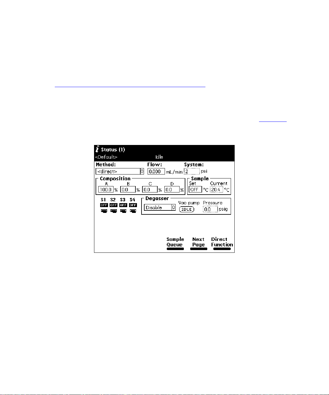
To control the operation of the in-line vacuum degasser from the Status screen:
1. Press the
The content and layout of the Status screen varies with the options installed in the
Separations Module and with the mode of operation.
2. Press the
3. Select the
modes. The modes are:
•
•
•
4. Select the desired operating mode, then press
Menu/Status
Next Page
Degasser
Normal
Continuous
Disable
– The degasser cycles on and off on a pressure-regulated cycle
– The degasser is always off
key. The Status screen appears, as shown in Figure 2-7
Figure 2-7 Status Screen
screen key (if necessary) to display the Degasser fields.
mode field, then press
– The degasser is always on
Enter
to display a list of degasser
Enter
.
.
The Vac pump field displays the current status of the vacuum degasser pump.
The Pressure field displays the current vacuum level in psig, bar, or kPa.
18 Preparing the Sepa rations Module for Operation
Page 19
Sparging
You set the initial and maintenance sparge cycles from the Sparge screen. You can set
diffe re n t spa rge cycl es for each of the fou r solvent reservoirs.
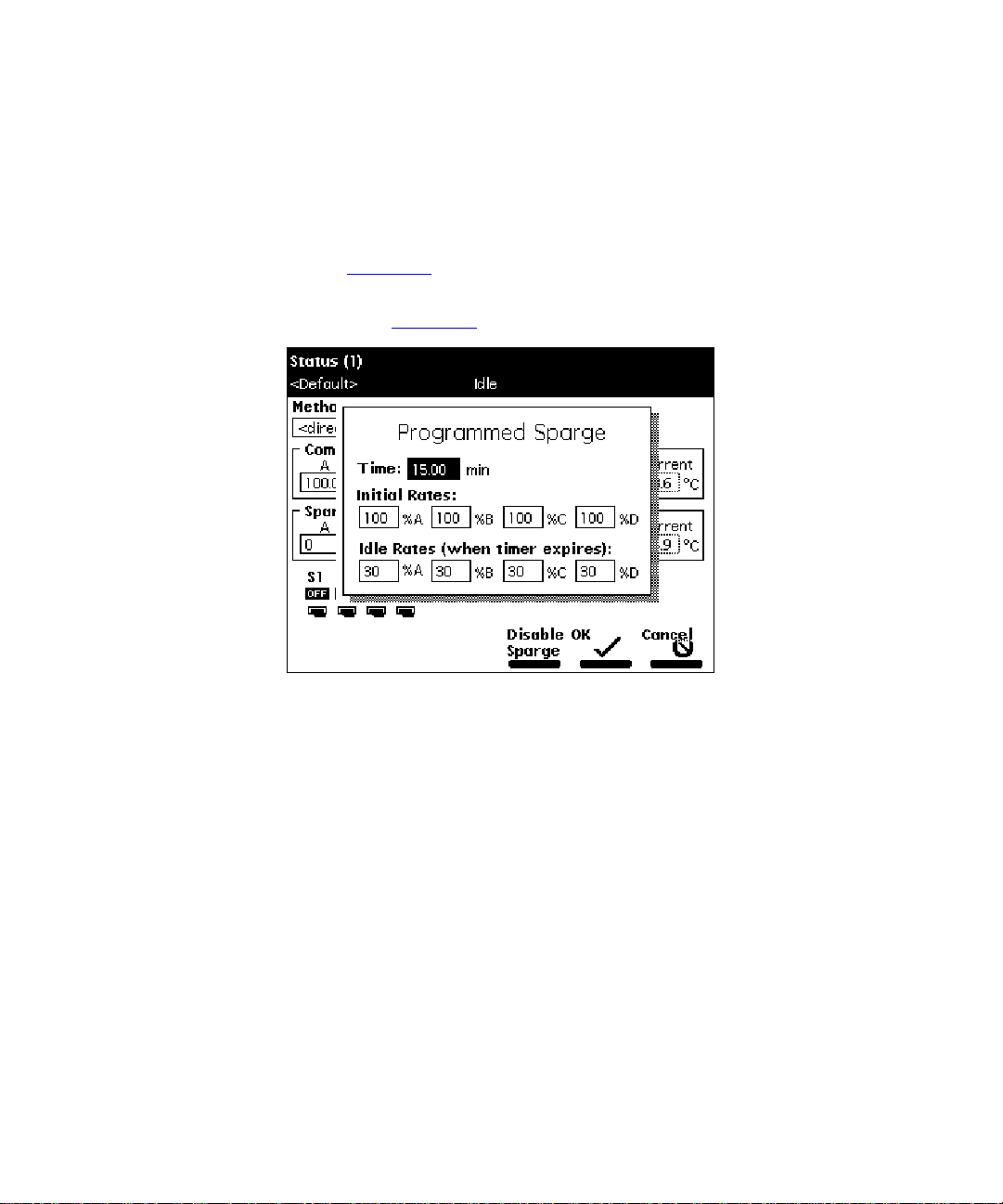
To program the sparge cycles from the Direct Function menu:
1. Press the
menu appears (Figure 3-4
2. Select the
dialog box appears (Figure2-8
3. In the Time field, enter the time to run the initial sparge cycle, then enter values
for each solvent reservoir for the following parameters:
Direct Function
Program Sparge
Figure 2-8 Programmed Sparge Dialog Box
screen key in the Status screen. The Direct Functions
).
option, then press
).
Enter
. The Programmed Sparge
• Initial sparge cycle rates
• Idle sparge cycle rate s
At a sparge cycle rate of 100%, the sparge valve is on at all times; at a sparge
cycle rate of less than 100%, the sparge valve turns on and off periodically.
Press the
reservoirs.
Press the OK screen key. The timer starts counting down, and the sparge gas
flows at the initial s parge cycle rates. The idle s parge cy cle rate begins when the
timer expires.
Disable Sparge
screen key if you do not want to sparge the
Preparing the Separations Module for Operation 19
Page 20
2.3.2 Priming the Solvent Management System
Dry Prime
Use the dry prime option to prime the system when the fluidic path in the solvent
management system is dry.
To perform a dry pri me:
1. S et up the reser voirs as described in the
Operator’s Guide
2. Inser t the solvent tubing into the appropriate reservoir(s). Be sure the detector
waste line and the sample loop waste line drain into an appropriate container.
3. Gently shake the filters in the reservoirs to remove any bubbles that may be
trapped.
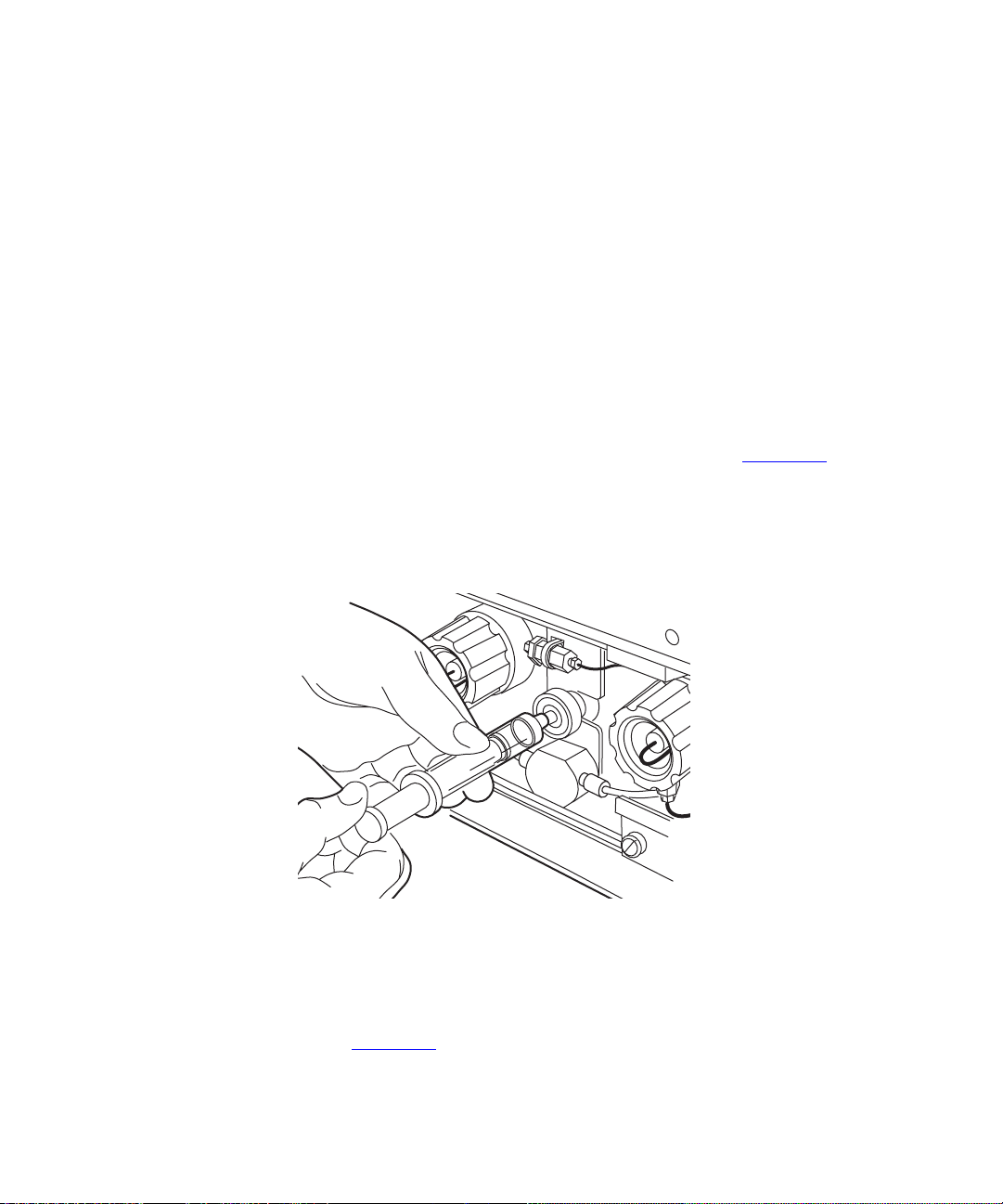
4. Attach an empty syringe to the prime/vent valve, as shown in Figure 2-9
open the valve by turning it counterclockwise 1/2-turn.
The syringe does not lock onto the prime/vent valve; hold it in place while you
Note:
. Section 2.6, Making Fluidic Connections.
Waters 2690 Separations Module
, then
pull on the plunger.
Figure 2-9 Prime/Vent V al ve with Syringe
5. Press the
menu appears (Figure 3-4
20 Preparing the Sepa rations Module for Operation
Direct Function
screen key in the Status screen. The Direct Functions
).
TP01359A
Page 21
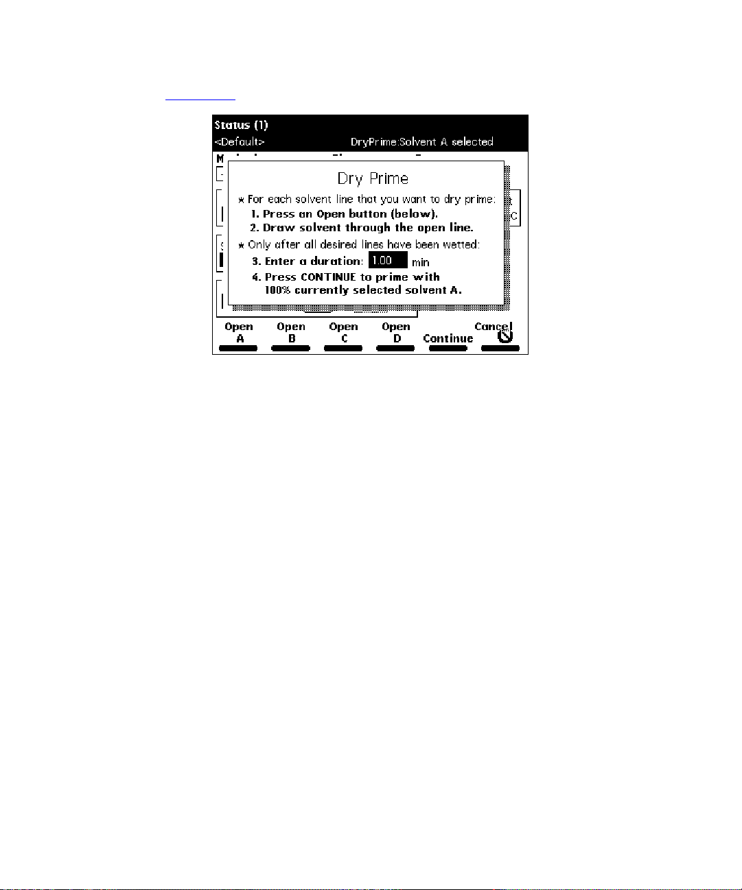
6. Sel ect
(Figure 2-10
Dry Prime
).
, then press
Enter
. The Dry P rime dialog box appears
Figure 2-10 Dry Prime Dialog Box
7. Press the screen key corresponding to the solvent line you want to prime.
8. Withdraw the syringe plunger to pull solv ent through the tubing. You may need t o
exert force to pull the air and solvent through the system. Continue until you pull
all the air through the solvent line into the syringe.
9. Repeat steps 7 and 8 for each solvent line you want to prime, then close the
prime/vent valve.
10. Press a screen key corresponding to the solvent line with which you want to
prime the system. Waters recommends that you prime using the solvent with the
lowest viscosity to help purge air from the lines, especially if the in-line vacuum
degasser is installed.
11. In the Enter a Duration field, enter the length of time (in minutes) to prime the
solvent management system. Start with a value of 5 minutes. Press
Continue.
The solvent management system begins to operate. At the end of the priming
period, the solvent management system turns off and the S eparations Module
enters the Idle mode.
12. Perform a wet prime (described below).
Preparing the Separations Module for Operation 21
Page 22
Wet Prime
STOP
STOP
Attention:
To avoid damage to the face seals
,
perform a wet prime only when there is
solvent in the solvent management system fluidic path.
Perform a wet prime when you want to change reservoirs or solvents, or if the Separations
Module has been idle for some time. The wet prime replaces solvent in the path from the
reservoirs to V3 (waste). If the solvent lines are dry, perform the dry prime procedure
before continuing.
Attention:
To av oi d precipitating salts in the Separations Module, use an intermediate
solvent such as water when you change from buffers to high-organic-content solvents.
Refer to the Waters 2690 Separations Module Operator’s Guide, Section D.3, Solvent
Miscibilit y, for informat ion on so lvent mis c ib il ity.
To perform a wet prime:
1. I n the Status screen Composition field, enter
use for wet priming. Waters recommends that you start the wet prime using the
solvent with the lowest viscosity to help purge air from the lines, especially if the
in-line vacuum degasser is installed.
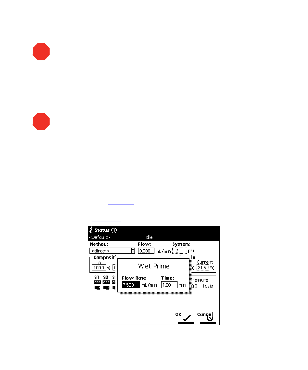
2. Press the
menu appears (Figure 3-4
3. Select the
appears (Figure 2-11
Direct Function
Wet Prime
option, then press
).
screen key in the Status screen. The Direct Functions
).
100%
for the first solvent you want to
Enter
. The Wet Prime dialog box
Figure 2-11 Wet Prime Dialog Box
22 Preparing the Sepa rations Module for Operation
Page 23

4. Gently shake the filters in the reservoirs to remove any bubbles that may have
formed.
5. Enter the flow rate and the duration of the prime (using the composition entered
in the Status screen), then press OK. The solvent management system begins
to operate.
At the end of the time period you specify, the solvent management system
returns to previous conditions and the Separations Module enters the Idle mode.
6. Repeat steps 1–5 for each solvent, as appropriate.
Equilibrating Solvents the Vacuum Degasser
Solvents are equilibrated in their respective degasser chamber by setting a zero flow rate
for a short time period. The steps that follow describe this process.
To equilibrate solvents the in-line vacuum degasser after you have wet primed the system:
1. E nter the initial solvent composition for the run in the Status screen.
2. Set the Degasser Mode parameter to
3. Press the
(Figure 3-4
4. Select
(Figure 2-11
5. Enter a flow ra te o f
period, the solvents are degassed and the Separations Module enters the Idle
mode.
The solvents in the in-line vacuum degasser are now equilibrated. Pr ime the
plunger seal wash pump as described below.
Direct Function
).
Wet Prime
, then press
).
screen key. The Direct Functions menu appears
Enter
0.000
mL/min and a time of 5 min. At the end of the time
Normal
. The Wet Prime dialog box appears
Continuous
or
.
Priming the Plunger Seal Wash Pump
For rev ersed-phase HPLC applications, use an aqueous plunger seal-wash solution with
enough organic content to inhibit bacterial growth. For example, use an 80%water:20%
methanol solution or an 80% water:20% acetonitrile solution, depending on your
application. For GPC separations, use a 50% methanol:50% water seal wash solution. If
required, use an intermediate solution to prevent immiscibility or precipitate problems
when you switch between GPC and reversed-phase analytical solvents.
To prime the plunger seal wash pump:
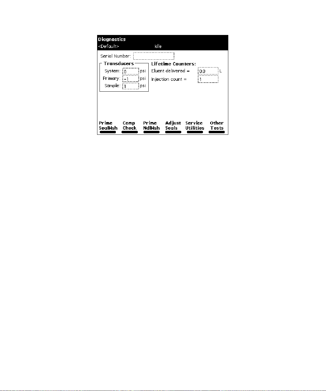
1. Press the
(Figure 2-12
Section 8.3, Performing Main Diagnostics, for more information on the Diagnostics
screen.
Diag
screen key in the Main screen. The Diagnostics screen appears
). Refer to the
Waters 2690 Separations Module Operator’s Guide
Preparing the Separations Module for Operation 23
,
Page 24
F98SM7885M
G98SM4582M
Figure 2-12 Diagnostics Screen
2. Attach the syringe adapter to the syringe (both are found in the Startup Kit).
3. Remove the inlet filter from the seal wash inlet tube.
4. Fill t he syr inge with the seal wash solution, then attach the syringe adapter to
the end of the seal wash inlet tube.
5. Press the
Prime SealWsh
screen key, then press the
Start
screen key. The seal
wash procedure begins. Push on the syringe plunger to force seal wash solvent
through the system.
6. When seal wash solvent flows out of the seal wash waste tube, press the
Halt
screen key.
7. Reinstall the inlet filter and place the seal wash inlet tube in the seal wash
reservoir.
8. Press
Close
to return to the Diagnostics screen.
Before you make a run, perform a Condition Column or Equilibrate direct function as
necessary.
24 Preparing the Sepa rations Module for Operation
Page 25
2.4 Preparing the Sample Management System
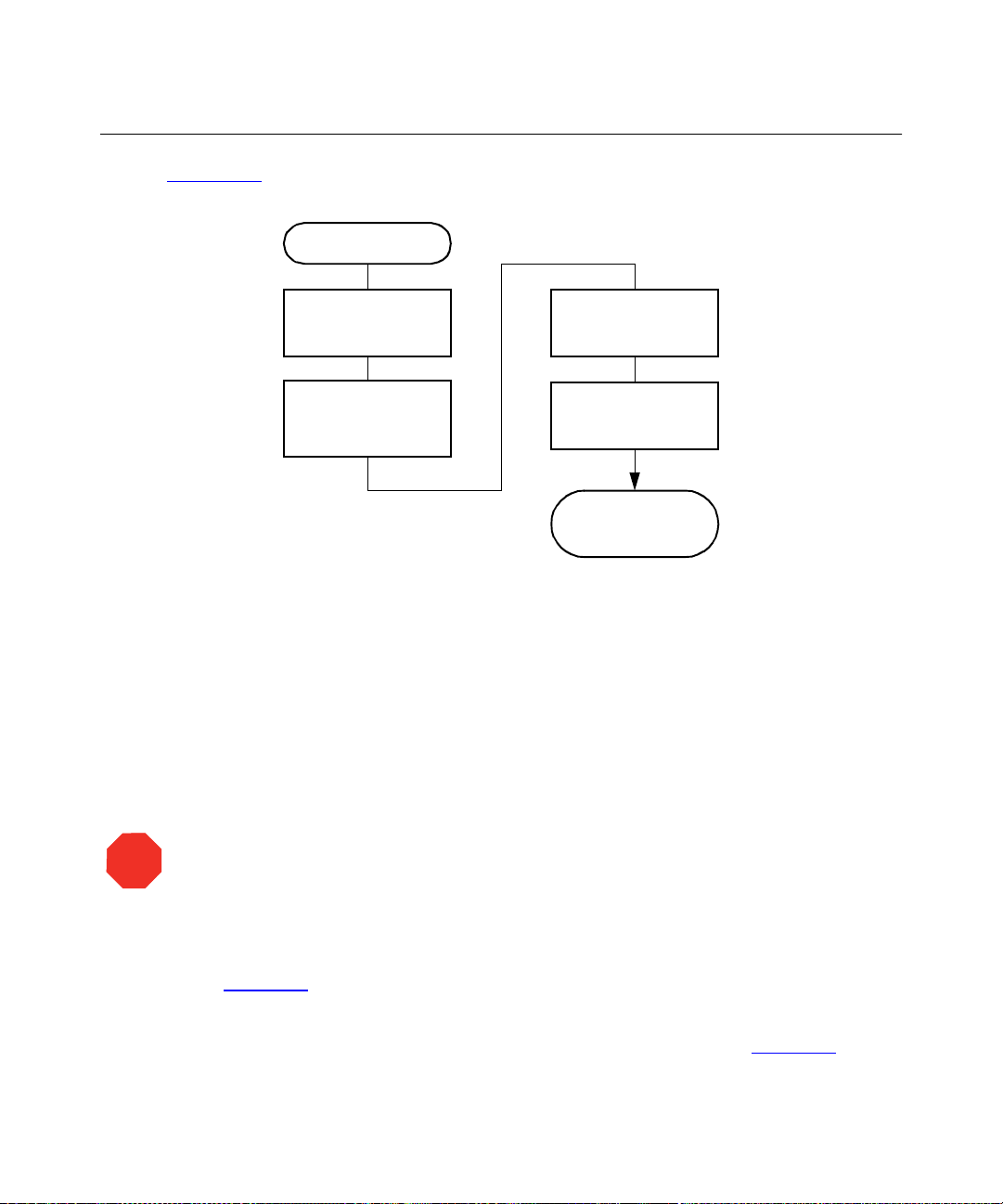
Figure 2-13 shows the steps in preparing the sample managemen t system for operation.
Start
Purge the Sample
Management
System
Prime the Needle
Wash Pum p
Figure 2-13 Preparing the Sampl e Manag eme nt System for Operation
Adjust the
Seal Pack
Load the
Carousels
Separations
Module is Ready
to Operate
2.4.1 Purging the Sample Management System
Purge the sample management system whenever you:
• Prime the solvent management system
• Change solvents
• See bubbles in the syringe
• Star t using the Separations Module at the beginn ing of each day
STOP
Attention:
To av oi d precipitating salts in the Separations Module, use an intermediate
solvent such as water when you change from buffers to high-organic-content solvents.
To purge the sample management system:
1. I n the Main screen, press the
(Figure 2-7
2. Enter the appropriate solvent composition in the Composition fields.
3. Press
).
Direct Functions
Menu/Status
to display the Direct Functions menu (Figure 3-4
Preparing the Separations Module for Operation 25
key to display the Status screen
).
Page 26
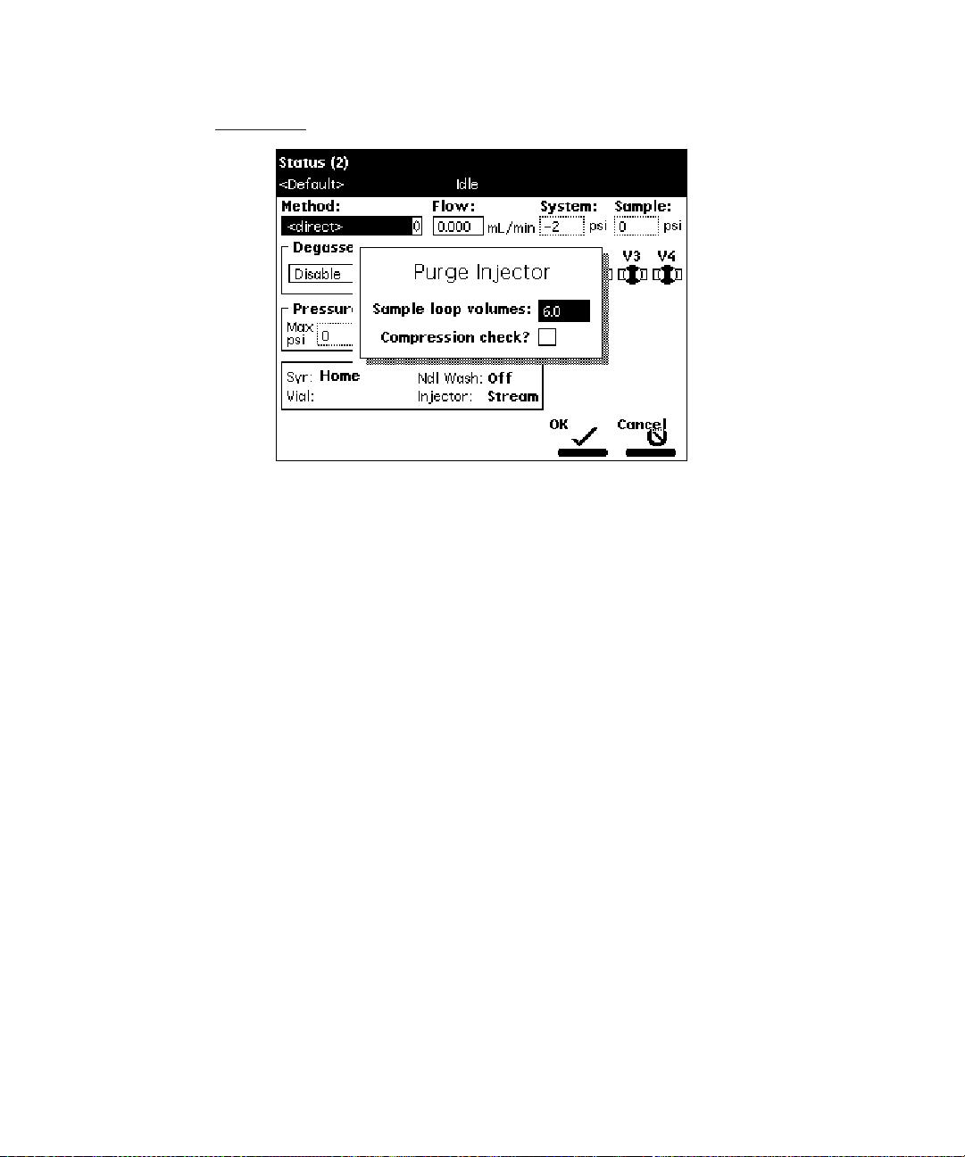
4. Select
(Figure 2-14
5. Enter the number of sample loop volumes in the Sample Loop Volumes field
(use the default value of 6.0 volumes), then press
management system ramps up to a predetermined flow rate to flush the sample
loop with the selected volume.
Purge Injector
).
Figure 2-14 Purge Injector Dialog Box
, then press
Enter
. The Purge Injector dialog box appears
Enter
. The solvent
6. Leave the Compression Check check box blank the first time you start up the
system to prevent a compression test from occurring. The Separations Module
does not allow a compression test before the seal pack is adjusted.
7. Press OK. The purge cycle begins.
2.4.2 Priming the Needle-Wash Pump
The needle-wash pump flushes the needle in the sample management system, preventing
carryover of sample between injections. The needle wash also extends the life of the
injector seals by removing buffered mobile phase and sample from the needle.
26 Preparing the Sepa rations Module for Operation
Page 27

Selecting a Needle-Wash Solvent
Use a needle-wash solvent based on the sample and mobile phase chemistries, making
sure all solutions/buffers are miscible and soluble. Table 2-1
solvents recommended for use with certain mobile phase conditions. High sample
concentrations may require other needle-wash solvents.
Table 2-1 Suggested Needle Wash Solvents
Chromatographic Condition Needle Wash Solvent
lists some needle-wash
Buffered aqueous,
reversed-phase
Non-aqueous, reversed-phase 100% MeOH
Normal phase Mobile phase
GPC Mobile phase
Ion exchange H2O
To prime the need le-wash pump:
1. B e sure the needle-wash fluidic lines are proper ly installed, as descri bed in the
Waters 2690 Separations Module Operator’s Guide
Wash and Plunger Seal Wash Reservoirs.
2. Press the
(Figure 2-12
3. Press the
begins. If solvent does not flow out of the waste tube within 30 seconds, press
the
Diag
).
Prime NdlWs h
Start Again
screen key in the Main screen. The Diagnostics screen appears
screen key.
2.4.3 Adjusting t he Seal Pack
90% H2O, 10% MeOH
, Section 2.6.6, Installing Needle
screen key. The 30-second needle-wash procedure
Adjust the seal pack whenever:
• You start up the Separations Module for the first time. The Separations Module does
not perform injections and compression checks until the seal pack has been
adjusted.
• A “Compression Check Failed” error appears on the screen
• A “Missing Restrictor” alarm appears during a diagnostic procedure
Preparing the Separations Module for Operation 27
Page 28
• You change the seal pack
• You rebuild the seal pack
Before you adjust the seal pack, purge the sample management system (Section 2.4.1,
Purging the Sample Management System) to ensure that there is no air in the syringe. Air
in the system may cause Alarm Seal Geometry or Alarm Missing Restrictor dialog boxes
to erroneously appear.
To adjust the seal pack:
1. Press the
2. Press the
test is complete, the results are shown in the dialog box that appears.
Diag
screen key in the Main screen to display the Diagnostics screen.
Adjust Seals
2.4.4 Loading Carousels
Loading carousels involves:
• Loading the vials into the carousel
• Loading the carousel into the sample compartment
Loading Vials
Use only 12 × 32 mm, 2-mL vials with snap-on, crimp-on, or screw-on caps.
Insert the prepared vials into the appropriate positions in the carousel(s). Be sure to place
vials in the numbered slots that correspond to the sample set (if any) you are using. If you
are not using a sample set, enter the sample vial positions in the Inject Samples dialog
box. If you are using the bar code option, make sure you have correctly attached labels to
the vials.
Loading the Carousel
Table 2-2 lists the carousels and their color codes.
screen ke y. The adjustment procedure begins. When the
Table 2-2 Carousel Codes and Colors
Code Color Vial Numbers
A Blue 1 to 24
B Yellow 25 to 48
C Red 49 to 72
28 Preparing the Sepa rations Module for Operation
Page 29
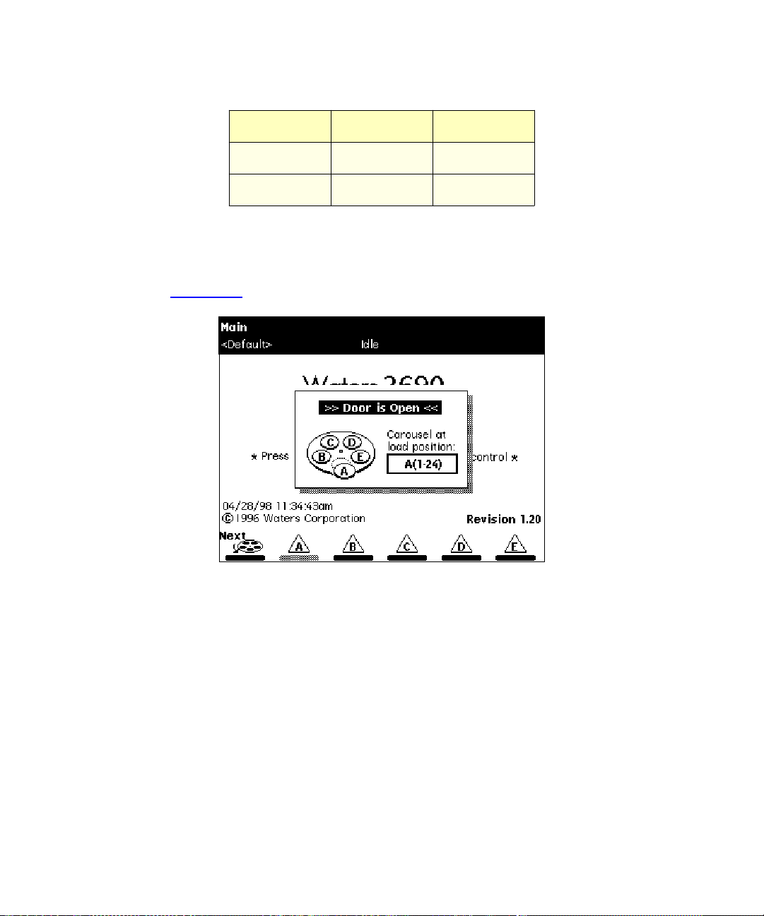
Table 2-2 Carousel Codes and Colors
(Continued)
Code Color Vial Numbers
D Green 73 to 96
E White 97 to 120
To load the carousels:
1. Open the carousel door. The Door is Open dialog box appears in the screen
(Figure 2-15
).
Figure 2-15 Door is Open Dialog Box
2. Press the
Next
screen ke y (or select the des i red carousel screen key) to position
the carousel turntable for loading the appropriate carousel.
3. Load the carousel into the sample compartment.
4. Repeat steps 2and 3 until all appropriate carousels are loaded.
5. Close the carousel door. If you enable the “Verify carousel placement” chec k box
(the default setting) in the Configuration screen, an error message appears if
you attempt to make an injection from a carousel that is in the wrong position.
Preparing the Separations Module for Operation 29
Page 30
3 Performing a Direct Control Run
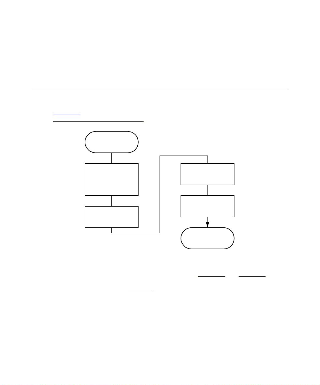
This section describes the procedures for performing a direct control (manual) run.
Figure 3-1
Section 4,
provides an overview of the procedures. To make an automatic run, refer to
Making Automatic Runs.
/
Menu
Press
Status
Key
Select Separa ti on
Method, or Enter
Par ameter V alues in
the Status Screen
Press the
You perform direct control runs from the Status screen (Figure 3-2
fields in the Status screen indicate the status or values of the current operating
parameters, as described in Table 3-1
values for certain parameters.
Direct
Function
Screen K ey
Figure 3-1 Setting Up a Direct Control Run
. The Status screen also allows you to enter new
Select the Direct
Function to Perform
Enter the Function
Parameters
The Function
Begins to Run
and Figure 3-3). The
30 Performing a Direct Control Run
Page 31
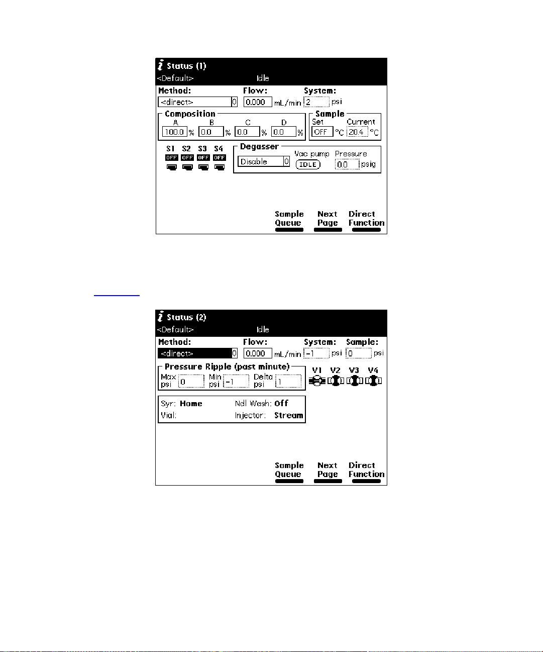
Figure 3-2 First Page of Status Screen
Press the
(Figure 3-3
Next Page
).
screen key to display the second page of the Status screen
Figure 3-3 Second Page of Status Screen
Performing a Direct Control Run 31
Page 32
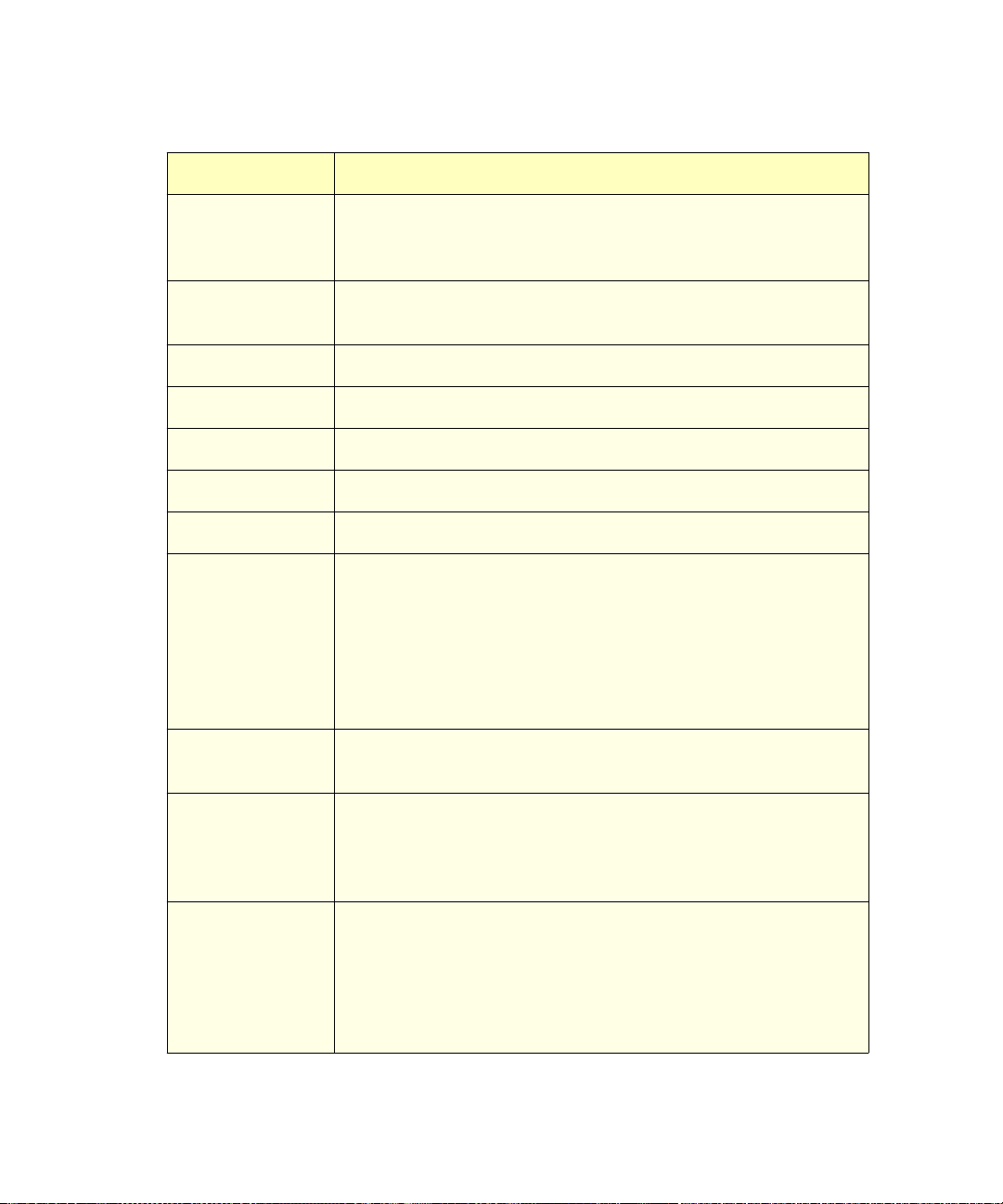
Table 3-1 Status Screen Parameters
Parameter Description
Method Indicates the current separation method. When you change
any parameter in the Status screen, this field changes to
<direct>.
Flow Indicates the current flow rate of the solvent management
system.
System Indicates the current system pressure in psi, bar, or kPa.
Sampl e : S e t Indicates the user-specified sample compartment temperature.
Sample: Current Indicates the current actual sample compartment temperature.
Composition Indicates the current solvent composition.
S1 – S4 Indicates the status of the event switches on the I/O connector.
Degasser
•Mode
• Vac pump
• Pressure
Indicates the status of the in-line vacuum degasser (if
installed) .
Selects the mode of operation: Normal, Continuous, or
Disable
Indicates whether the vacuum pump motor is active or idle.
Current vacuum level in psi, bar, or kPa.
Sparge Indicates the sparg e rat e cycle for each solvent (if sparge is
installed)
V1 – V4 Indicates the position (open or closed) of each of the valves in
the sample management system. See the
Separations Module Operator’s Guide
Waters 2690
, Section 1.3, Sample
Management System Overview, for a description of the valves.
Pressure Ripple
Indicates pressure readings in the solvent management system
for the last minute.
• Max psi
•Min psi
•Delta psi
Maximum pressure.
Minimum pressure.
Peak-to-peak pressure difference.
32 Performing a Direct Control Run
Page 33
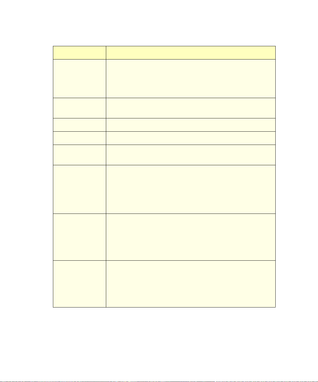
Table 3-1 Status Screen Parameters
(Continued)
Parameter Description
Syr Indicates the current position of the syringe. V al i d positions are:
• Home – Default position
• Empty – Highest position (to purge the syringe)
• Full – Lowest position (to draw in sample)
Vial Indicates the number of the vial that is currently under the
injector.
Ndl Wash Indicates whether the needle-wash pump is on.
Sample Indicates the current pressure in the sample loop.
Column Temp Indicates the desired and current temperature of the column (if
the column heater is installed).
Injector Indicates the current position of the injector . Valid positions are:
• Stream – In the high pressure stream
• Seal – In the lower seal position
• Wet – In the needle wash position
• Vial – In the sample vial
486 (1) and (2)
λ
•
• Lamp
•AUFS
2487 (1) and (2)
λ
•
• Lamp
•AUFS
Indicates the current status of the following parameters for the
486 detector(s) (if installed).
• Wavelength
• Lamp On or Off
• Absorbance Units Full-Scale
Indicates the current status of the following parameters for the
2487 detector(s) (if installed):
• Wavelength
• Lamp On or Off
• Absorbance Units Full-Scale
Performing a Direct Control Run 33
Page 34
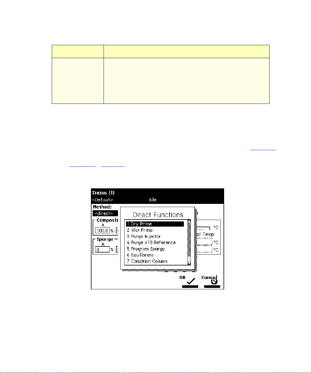
Table 3-1 Status Screen Parameters
(Continued)
Parameter Description
2410 and 410
Indicates the current status of the following parameters for the
2410 or 410 detector (if installed):
•Cell
•Col 1
•Col 2
1
Enabled if the optional column heater module is configured with the Waters 2410 or
410 detector.
• Cell Temperature
• External Temp 1
• External Temp 2
1
*
To access the direct control functions:
1. Press the
2. Press the
(Figure 3-4
Menu/Status
Direct Function
key (if necessary) to display the Status screen (Figure 3-2
screen key. The Direct Functions menu appears
). Table 3-2 describes each of the direct functions.
3. Select the function you want to specify (press t he number beside the function, or
use the arrow keys), then press
Enter
. Follow the instructions for each function.
).
Figure 3-4 Direct Functions Menu
34 Performing a Direct Control Run
Page 35
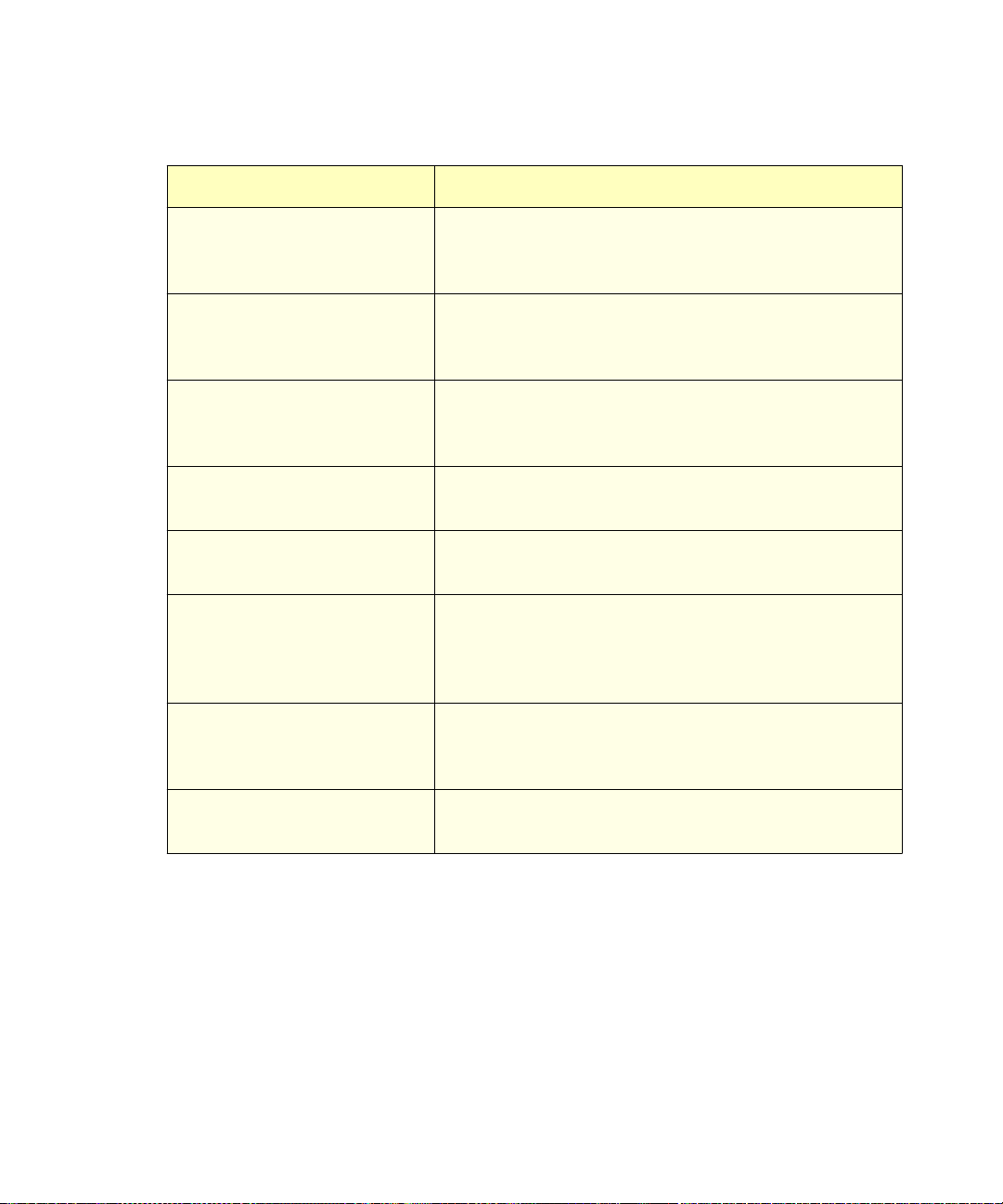
Table 3-2 Direct Functions
Direct Control Function Description
Dry Prime Opens the fluidic path (from the selected solvent
reservoir to the prime/vent valve) to replace air with
solvent, then performs a prime.
We t P ri me Replaces solvent in the path from the reservoirs to V1
and then to waste. Use to change the solvent(s) in the
system.
Purge Injector Removes mobile phase from the sample loop and from
the syringe and fills it with fresh mobile phase. As an
option, performs a compression test.
Purge 2410/410 Reference
(if applicable)
Program Sparge (if
Purges the Waters 2410 or 410 RI detector reference
cell.
Sets the sparge rate for each reservoir.
applicable)
Equilibrat e Delivers mobile phase at the current conditions for the
specified period of time. Equilibrates the temperature
in the sample compartment and column heater at
preset values.
Condition Column Delivers mobile phase using the gradient table
specified in the current separation method without
injecting a sample or running the Events table.
Inject Samples Injects a sample one or more times from the specified
vial(s) using the selected method.
Performing a Direct Control Run 35
Page 36

4
Making Automatic Runs
This chapter describes how to set up the Separations Module to make automatic runs in:
• System Controller or No Interaction mode
• Controlled by Millenniu m Chro m ato graphy Manager modes (2.xx or Millennium
• Controlled by MassLynx mode
System Controller or No Interaction Mode
If your HPLC system uses the 2690 Separations Module in a System Controller or No
Interaction mode, you make an automatic run using a sample set or sample template
stored in the Separations Module. Refer to Section 4.1,
Stand-Alone Mode, for details. Refer to the
, Chapter 6, Creating Separation Methods, Sample Sets, and Templates, for
Guide
information on creating and editing separation methods, sample sets, and sample
templates.
Controlled By Millennium Chromatography Manager Modes
If your HPLC system is controlled by the Millennium Chromatography Manager, you make
an automatic run using a project, instrument method, and sam ple set stored in the
Millennium Chromatography Manager. Refer to the procedures in Section 4.2,
Automatic Runs Under Millennium Control, f or details on making a run using Millennium
software.
Waters 2690 Separations Module Operator’s
Making Automatic Runs in
Making
32
)
Controlled By MassLynx Mode
If your HPLC system is controlled by Micromass MassLynx software, you make an
automatic run using the sample processing list containing the LC method(s) that define the
Separations Module and detector (other than the MS detector) operating parameters.
Refer to Section 4.3,
making a run using MassLynx software.
36 Making Automatic Runs
Making Automatic Runs Under MassLynx Control, for details on
Page 37
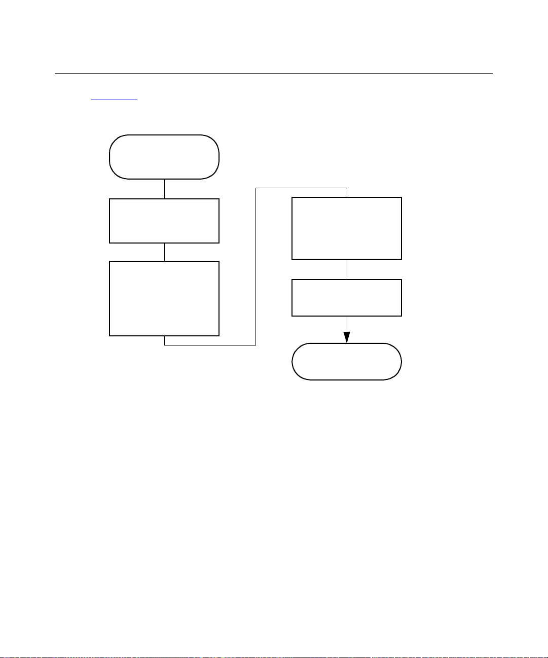
4.1 Making Automatic Runs in Stand-Alone Mode
Figure 4-1 shows the steps for setting up and making an automatic run with a Separations
Module in a stand-alone configuration (System Controller or No Interaction mode).
Press the
Samples
on the Main Screen
Run
Screen K ey
Select the Separation
Method, Sample Set, or
Sample Template to Run
Press the
Ke y to Select Condit ions,
or Press the
Conditions
Key to Start the Solvent
Management System
Run
Screen
Initial
Screen
Enter Information
Required by the
Separation Method,
Sample Set, or Sample
Template
Press the
Screen Ke y to Begin
The Run Ends as
Routine
the Run
Programmed
Figure 4-1 Making an Automatic Run in a Stand-Alone Configuration
Making Automatic Runs 37
Page 38
Running a Sample Set
If you plan on importing sample sets stored on a diskette, refer to the “Importing
Note:
Methods” discussion at the end of this section.
To run a sample set in a standalone mode:
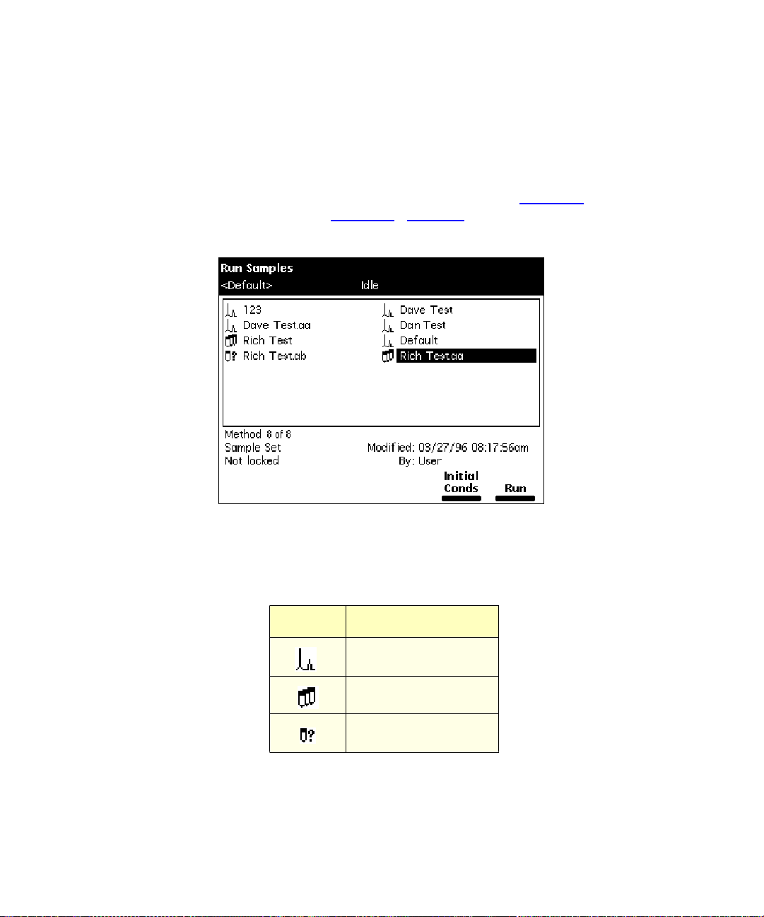
1. Press the
Samples screen appears (Figure 4-2
Run Samples screen.
Run Samples
Figure 4-2 Run Samples Screen
Table 4-3 Icons in the Run Samples Screen
screen key in the Main screen (Figure 2-2
). The Run
). Table 4-3 describes the icons used in the
2. Select the sample set you want to run.
3. Press one of the following screen keys to perform the indicated tasks:
38 Making Automatic Runs
Icon Description
Separation Method
Sample Set
Sample Template
Page 39
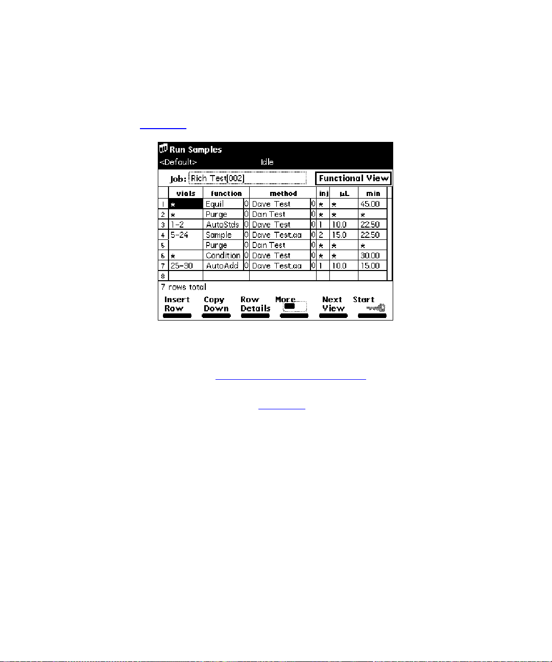
Initial Conds
•
– Starts the solvent management system at the initial conditions
(specified in the first line of the sample set) and begins equilibrating the
temperature in the sample heater/cooler and/or column heater. When the
system is equilibrated, press the
Run
•
– Displays the selected sample set table (to view or edit), as show n in
Figure 4-3
. Use the screen keys to modify the table as necessary.
Run
screen key.
Figure 4-3 Sample Set Screen – Functional View
4. Load the sample vials into the carousel(s) according to the locations specified in
the sample set (see Section 2.4.4,
5. Press the
Start
screen key. The Run Samples screen appears with a list of the
solvents required for the run (Figure 4-4
Loading Carousels).
). Check that you have prepared the
Separations Module with the indicated solvent(s).
Making Automatic Runs 39
Page 40
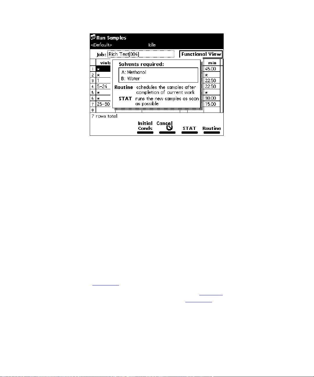
Figure 4-4 Run Samples Screen with Solvents Required Dialog Box
6. Press the
refer to the “Editing a Separation Method” discussion that follows. To make a stat
run, refer to the “Stat Run” discussion that follows.
Routine
screen key to start a norm al r un. To modify a run in progress,
Making a Run From a Sample Template
If you plan on importing sample templates stored on a diskette, refer to the
Note:
“Importing Me thods” discuss ion at the end of this section.
You can perform an automated run in a stand-alone mode using a sample template stored
in the Separations Module. Screen prompts give you step-by-step directions to prepare for
the run. Refer to the
Creating Methods, Sample Sets, and Sample T e mplates, for a description of sample
templates.
To run a sample template in a standalone mode:
1. Press the
appears (Figure 4-2
2. Select the sample template you want to run (see Table 4-3
The Setup dialog box appears, as shown in Figure 4-5
Waters 2690 Separations Module Operator’s Guide
Run Samples
screen key in the Main screen. The Run Samples screen
).
.
, Chapter 6,
), then press
Enter
.
40 Making Automatic Runs
Page 41
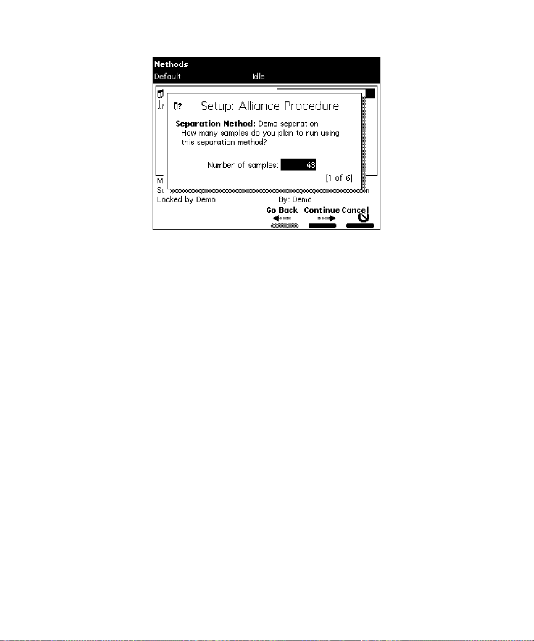
Figure 4-5 Setup Dialog Box
3. Enter the number of samples to run, then press the
4. Enter the location of the first sample vial, then press the
You must use consecutive sample vials on one or more carousels.
5. Repeat steps 3 and 4 if t he sample template includes multiple separation
methods.
6. Enter the number of standards in the run, then press the
7. Enter the location of the first standard vial, then press the
You must use consecutive standard vials.
8. Make sure that the solvents listed in the dialog box are primed and in the
appropriate inlet tubes, then press the
Start
screen key.
Continue
Continue
Continue
Continue
screen key.
screen key.
screen key.
screen key.
Modifying a Sample Set During a Run
You can modify operating conditions during a run in a stand-alone mode by:
• Using the stat run function
• Editing the separation method
Performing a Stat Run
You can use the stat run function to interrupt a run in progress and perform one or more
injections after the current injection is done, then continue with the scheduled run.
Performing a stat run is most useful when running separation methods that use identical
solvents and temperatures.
Making Automatic Runs 41
Page 42

To perform a stat run
1. Load the sample(s) into the carousel, then place the carousel in the sample
compartment.
2. Press the
screen appears (Figure 4-2
3. Select the separation method or sa mple set you want to use for the stat run, then
press the
4. Enter the carousel position of the vial(s) and other parameters in the appropriate
fields in the screen.
5. Press the
for the run, as shown in Figure 4-4
Separations Module with the indicated solvent(s).
6. Press the
injection is complete. The original sample set resumes after the stat run is
complete.
Editing a Separation Method
You can modify a separation method while a sample set is running. If the separation
method is being used for the current injection, the current injection is not affected by the
changes. You must save the changes to the modified separation method before you can
apply the method to all subsequent injections that use that separation method. Use the
procedures in the
Creating and Editing Separation Methods, to modify and save the separation method.
while a sample set is running:
Run Samples
Run
screen key.
Start
screen key. A screen appears with a list of the solvents required
Stat
screen key. The stat r un s tarts immediately after the current
Waters 2690 Separations Module Operator’s Guide
screen key in the Main screen. The Run Samples
).
. Check that you have prepared the
, Section 6.1,
Importing and Exporting Methods
You can use the floppy disk drive in the Separations Module to import and export
separation methods, sample sets, and sample templates to 1.44-MB, standard
PC-formatted floppy disks. Also, by saving reports and tables to a floppy disk, you can use
the disk drive as an alternative to a hard-copy printer.
Importing Methods
To import one or more methods from a floppy disk:
1. I nsert the disk that contains the method(s) into the floppy disk drive.
2. Press the
key twice to access the Methods screen (Figure 4-7
3. Press the
displaying a list of methods stored on the disk (Figure 4-6
press the
42 Making Automatic Runs
Methods
Import Methods
Refresh
screen key in the Main screen, then press the
screen key.
More
screen
).
screen key. The Import Methods screen appears,
). To update the list,
Page 43
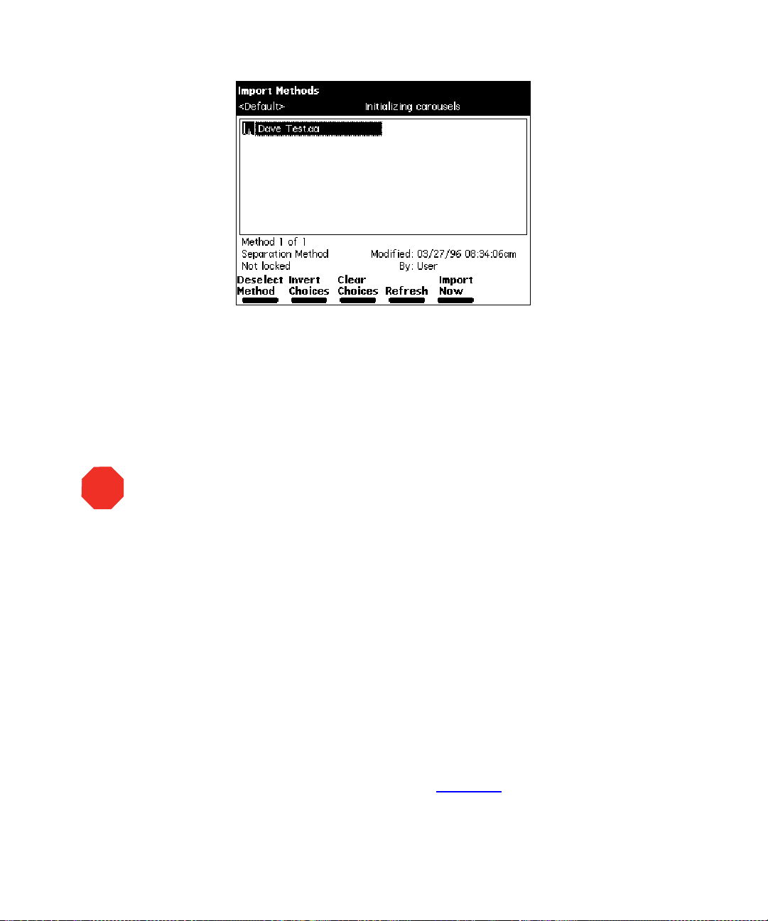
Figure 4-6 Import Methods Screen
4. Select the method you want to impor t into the S eparations Module, then press
Select Method
the
and press
5. After you select all the methods you want to import, press the
screen key. The file transfer begins.
Select Method
screen key. To select additional methods, select each method
again.
Import Now
STOP
Attention:
complete; the Separations Module cannot detect a partially imported method.
Waters recommen ds that yo u caref ully review any importe d meth od b efore you run
the method.
Expor ting Me thods
To export one or more separation methods, sample sets, or sample templates to a floppy
disk:
1. I nsert a preformatted 3.5-inch disk into the floppy disk drive in the Separations
2. Press the
Do not remove the flop py disk fro m the dr ive before the i mpo r t is
An error message appears if you attempt to import a method that already exists
in the Separations Module. You can choose to overwrite the existing method.
An error message appears if you attempt to transfer more than 60 methods into
the Separations Module.
Module.
Methods
key twice to access the Methods screen (Figure 4-7
screen key in the Main screen, then press the
).
Making Automatic Runs 43
More
screen
Page 44
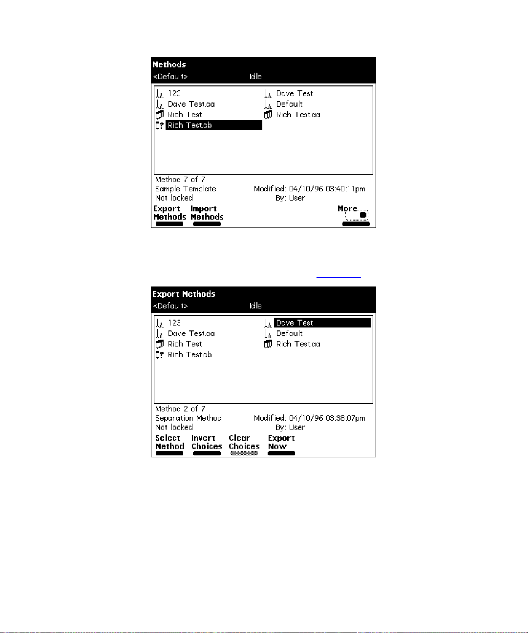
Figure 4-7 Methods Screen
3. Press the
displaying a list of currently stored methods (Figure 4-8
Export Methods
screen key. The Expor t M ethods s creen appears,
).
Figure 4-8 Export Methods S creen
4. Select the method you want to export to the disk, then press
select an additional method, select the method desired, then press
Method
again.
To select all methods except the Default method:
a. Select the
b. P ress t he
Default
method, then press the
Invert Choices
screen key. All methods except the Default method
Select Method
are selected.
Select Method
Select
screen key.
. To
44 Making Automatic Runs
Page 45

5. When you have selected all the methods you want to transfer, press the
Now
screen key. T h e fi l e tran sfer begins.
Export
4.2 Making Automati c R uns Unde r Mil len niu m Contro l
If your Separations Module is configured for Millennium Chromatography Manager control
(Millennium version 2.xx or Millennium
(QuickSet in Millennium versions earlier than 3.20) in the Millennium software. When the
Separations Module is running under Millennium control, the word “Remote” appears in
the banner area.
32
), you make an automatic run from Run Samples
Making a Run Using Millennium Software
To make an automatic run, perform the following steps at the Millennium workstation:
1. Create a chromatographic system that includes the Waters 2690 Separations
Module:
• For Millennium software version 2.1x, create a system that includes the 2690
solvent management system and the sample management system. Refer to the
Millennium documentation for information on creating a chromatographic
system.
• For Millennium
Separations Module. Refer to the
creating a chromatographic system.
2. Create a Millennium instrument method that uses the system you created in step
1, a bove. Refer to the Millennium documentation for information on creating and/or
modifying an instr um e n t me t ho d.
32
software, create a system that includes the Waters 2690
Millennium Online Help
for information on
Any parameter values not explicitly set in the Millennium ins tr um ent met hod
Note:
automatically take on the values in the Default separation method in the Separations
Module.
You can edit the Default separation method in the Separations Module to set
parameter values appropriate for your applications.
3. Create a method set that uses the instrument method you created in step 2,
above. Re fer to the M i lle nnium document ation f or information on cre atin g and/or
modifying a method set.
Making Automatic Runs 45
Page 46

4. From Millennium³² software, run the samples in Run Samples (QuickSet in
Millennium versions earlier than 3.20) using the method set you created in step
3 above. When you enter Run Samples, use the HPLC system you created in
step 1, above. Refer to the Millennium documentation for information on using Run
Samples.
5. Process and pr int out the dat a acquired from the chromatographic run. Refer to
the Millennium documentation for information on developing a processing method.
You can operate the Separations Module from its front panel whenever Run
Note:
Samples is not running on the Mille nnium C hroma tography Manager workstation.
4.3 Making Automatic Runs Under MassLynx Control
If your Separations Module is configured for MassLynx software control (versions 3.1,
Build 004 and later), you make an automatic run from the MassLynx software. When the
Separations Module is running under MassLynx control, the word “Remote” appears in the
banner area.
Making an Automatic Run Using MassLynx Software
To make an automatic run, perform the following steps at the Micromass MassLynx
computer:
1. Con figure an LC-MS system that includes the Separations Module. Refer to
MassLynx online Help for information on configuring an inlet system.
2. From the Inlet Editor, create an LC method for the Separations Module and
detector (other than the mass spectrometer). Refer to MassLynx online Help for
information on using the Inlet Editor.
3. Acquire a single sample from the Inlet Editor. To acquire multiple samples, create a
sample processing list from the MassLynx Top Level screen. Refer to MassLynx
online Help for information on sample processing lists and acquisition.
4. Process and print out the data acquired from the chromatographic run. Refer to
MassLynx online Help for information on processing data.
You can operate the Separations Module from its front panel whenever MassLynx is not
running.
46 Making Automatic Runs
Page 47

4.4 Stopping a Run
To stop a run in progress, press one of the following keys from the Status screen:
Stop Inject
•
requesting you to abort or resume the injection
Hold Inject
•
subsequent functions, and displays screen keys that allow you to abort or resume
the sample set
Hold Gradient
•
allows you to resume the gradient
Stop Flow
•
current function, and displays screen keys that allow you to abort or resume the
function
If any alarm condition specified in the separation method, sample set, or sample template
is set to “Stop Function” or “Stop Flow” and the alarm condition occurs, a dialog box
appears notifying you of the alarm condition. The following screen keys are in this dialog
box:
Abort
•
Resume
•
(screen key) – Stops the current injection and displays a dialog box
(screen key) – Completes the current function, suspends operation of
(screen key) – Holds the current gradient conditions. A screen key
(on the keypad) – Stops the flow of solvent, suspends operation of the
– Cancels the current function
– Resumes the current function
Making Automatic Runs 47
Page 48

5 Po w ering Off t he Sepa r ati ons Module
Before Powering Off
Before you power off the Separations Module, remove any buffered mobile phase present
in t he flu idic path .
STOP
Attention:
following procedure.
To remove buffered mobile phase from the fluidic path of the Separations Module:
P o w e ring Off
To power off the Separations Module:
To avoid damaging your column, remove the column before you perform the
1. Rep lace the buffered mobile phase with HPLC-quality water and prime the system
for 10 minutes at 3 mL/min (see the Section 2.3.2,
System, the “Wet P rim e” discussion).
2. Perform three injector purge cycles to ensure that the sample loop is clean (see
Section 2.4.1,
3. Replace the plunger seal wash solvent with a fresh solution of 80% water:20%
methanol or a miscible solvent, and prime the plunger seal wash pump (see
Section 2.3.2,
Seal Wash Pump” discussion).
4. Replace the water mobile phase with a solution of 90% methanol:10% water,
and flush the system for 10 minutes at 3 mL/min.
5. Replace the needle-wash solvent with a solution of 90% methanol:10% water or
a miscible solvent, and perform a needle-wash prime (see Section 2.4.2,
the Needle-Wash Pump).
Purging the Sample Management System).
Priming the Solvent Management System, the “Prim ing the Plunger
Priming the Solvent Management
Priming
1. E nsure that the system has been flushed properly (see the “
discussion above).
2. Press the power switch to the 0 (Off) position. The time and date of power-off are
entered in the log file.
48 Powering Off the Separations Module
Before Powering Off”
Page 49

6 Recommended Preparation Procedures
This chapter outlines the steps to prepare both degasser and sparge-based 2690
Separations Modules for operation using Waters-recommended procedures. Flow charts
provide the sequence of steps to prime, equilibrate, and purge a Separations Module that
is in one of the following states:
• A new or dry Separations Module
• A Separations Module that has been turned of f or left idle with no flow
• A Separations Module that requires a solvent change, such as from a buffered
solvent to an organic solvent
For step-by-step instructions on how to use Direct Functions to prime, equilibrate, and
purge your Separations Module, refer to the
, Chapter 4, Section 4.4, Performing Direct Functions.
Guide
All flow chart references in this chapter refer to sections or figures in the Waters
Note:
2690 Separations Module Operator’s Guide.
Waters 2690 Separations Module Operator’s
Recommended Preparation Procedures 49
Page 50
Figure 6-1 outlines how to prime, equilibrate, and purge a sparge-based Separations
Module that is new or dry.
All flow chart references refer to sections in the Waters 2690 Separations Module
Note:
Operator’s Guide.
Start
Fill the Solvent
Reservoirs with
Fr esh Solvent
Filtered and
Degassed by
Vacuum Filtration
(See Section 2.6.3)
Sparge all
Reservoirs at an
Initial Spar g e Rate
of
Least 15 min. Set
an Idle Sparge Rate
of
(See Section 4.4.4)
Per form a Dry
Prime (to Fi ll Ea ch
Solvent Line) See
Section 4.4.1
Perform a Wet
Prime (for One of
the Solv ents) for
min at
(See Section 4.4.2)
100%
30
to
5.00
for at
50%
mL/min
5
To Make a Gradient
Run (for Example,
A:B), Set the A and
B Composition
Fields in the Status
Screen to
then Wet Prime f or
min at
(See Section 4.4.2)
Equilibrate for a
Minimum of 10
Column Volumes
(See Sec tion 4.4.5)
Purge the Injector
for a Minimum of 6
Loop Volumes
(See “Purging the
Section 4.4.2)
50%
5.00
mL/min
Injector” in
,
2
Repeat the Wet
Prime (at the S a me
Rate and Time) fo r
Each Solvent
Figure 6-1 Preparing a New or Dry Separations Module for Operation (Sparge-Based Unit)
50 Recommended Preparati on Procedures
Page 51
Figure 6-2 outlines how to prime, equilibrate, and purge a vacuum degasser-based
Separations Module that is new or dry.
All flow chart references refer to sections in the Waters 2690 Separations Module
Note:
Operator’s Guide.
Start
To Make a Gradient
Run (for Example,
A:B), Set the A and
B Comp osit io n
Fields in the S tat us
min. at
mL/min.
50%
5.00
,
Screen to
Then Wet Pri m e for
2
(See Section 4.4.2)
Set the Degas ser to
Norma l
(See “Equilibrating
Solvents in the
Vacuum Degasser ”
in Section 4.4.1)
Equilib ra t e for a
Minimum of 10
Column Volumes
(See Section 4.4.5)
Fill all Foura Solvent
Reservoirs with
Fr esh Solvent
Filtered and
Degassed by
Vacuum Filtration
(See Section2.6.2)
Set the Degasser to
Continuous
“Equilibra ting
Solvents in the
V acuum Degas ser”
in Section 4.4.1)
Perf orm a Dry Prime
(to Fill Each Solv ent
Line and
Degasser Chambe r)
(See Section 4.4.1)
(See
Equilibr ateb the
Solvent in the
Degasser Chambe r
by Setting a Flow
Rate of
mL/min for
(See “Equilibrating
Solvents in the
V acuum Degasser”
in Section 4.4.1)
Perform a Wet
Prime (for One of
the Solven ts) for
5.00
min at
(See Section4.4.2)
Repeat the Wet
Prime (at the Sam e
Rate and Time) for
Each Solvent
0.000
5
min.
mL/min
10
Purge the Injector
for a Minimum of 6
Loop Volumes
(See “Purging the
Injector” in
Section 4.4.2)
a
To maximize degasser efficiency (and fill all four degasser chambers with solvent), Waters recommends that
all four solvent reservoirs be filled (even if four solvents are not used). If you choose water as one of the
“unused” solvents, change the water weekly to prevent bacterial contamination.
b
Except for the short period of time required to equilibrate solvents in the degasser, do not run the degass er
without solvent flow. Refer to the “Degasser Considerations” discussion, Section 1.5, for more details.
Figure 6-2 Preparing a New or Dry Separations Module for Operation (Degasser-Based Unit)
Recommended Preparation Procedures 51
Page 52
Figure 6-3 outlines how to prime, equilibrate, and purge a sparge-based Separations
Module that has been powered off or is idle with no solvent flow.
All flow chart references refer to sections in the Waters 2690 Separations Module
Note:
Operator’s Guide.
Start
Repeat the Wet
Fill the Solvent
Reservoirs with
Solvent Filtered and
Dega s sed by
Vacuum Filtration
(See Section 2.6.3)
Sparge all
Reservoirs at an
Initial Sparge Rate
of
Least 15 min. Set
an Idle Sp arge Rate
of
(See Section 4.4.4)
100%
to
30
for a t
50%
Prime (at the Sam e
Rate and Time) f or
Each Solvent
To Make a Gradient
Run (for Example,
A:B), Set the A and
B Composition
Fields in the Status
Screen to
Then Wet Prime for
1
min at
(See Section 4.4.2)
50%
5.00
mL/min
,
Per form a Wet
Prime (for One of
5.00
2
the Solvents) for
min. at
mL/min. (See
Figure 6-3 Preparing an Idle or Powered-Off Separations Module for Operation
(Sparge-Based Unit)
52 Recommended Preparati on Procedures
Equilibrate for a
Minimum of 10
Column Volumes
(See Section 4.4.5)
Purge the Injector
for a Mini m um of 6
Loop Volumes
(See “Purging the
Injector” in
Section 4.4.2)
Page 53
Figure 6-4 outlines how to prime, equilibrate, and purge a vacuum degasser-based
Separations Module that has been powered off or is idle with no solvent flow .
All flow chart references refer to sections in the Waters 2690 Separations Module
Note:
Operator’s Guide.
Start
Set the Degasser to
Continuous
(See “Equi librating
Solvents in the
V acuum Degasser”
in Section 4.4.1)
Perf orm a Wet Prime
(for One of the
Solvents) for
7.500
(See Sec t io n 4 .4 .2 )
Repeat the Wet
Prime (at the Sam e
Rate and Time) f or
Each Solvent
2
min at
mL/min
Equilibratea the
Solvent i n the
Degasser Chamber
by Sett i n g a Flow
Rate of
mL/min for 5 min
(See “Equilibrating
Solvents in the
V acuum Degas ser”
Section 4.4.1
in
If You Want t o Mak e
a Gradient Run
(for Exampl e, A:B),
Set the A and B
Composition Fi elds
in the Status Scr een
50%
to
Prime for
5.00
(See Section4.4.2)
0.000
)
, Then Wet
3
min at
mL/min.
Set the Degasser to
Norma l
“Equilibrating
Solvents in the
V acuum Degasse r”
in Section 4.4.1)
Equilib ra t e for a
Minimum of 10
Column volume s
(See Section 4.4.5)
Purge the Injector
for a Minimum of 6
Loop Volumes
(See “Purging the
Section 4.4.2)
(See
Injector” in
a
Except for the sh ort period of time required to equilibrate solvents in the degas s er, do not run the degasser
without solvent flow. Refer to the “Degasser Considerations” discussion in S ection1.5 for mor e details.
Figure 6-4 Preparing an Idle or Powered-Off Separations Module for Operation
(Degasser-Based Unit)
Recommended Preparation Procedures 53
Page 54
Figure 6-5 outlines how to change from a buffered solvent to a totally organic solvent in a
sparge-based Separations Module.
All flow chart references refer to sections or figures in the Waters 2690 Separations
Note:
Module Operator’s Guide.
Start
Remove the Solv ent
Line from the
Reservoir Containi ng
the Buffered Solvent
Using a Flow Rat e of
2.000
mL/min,
Perf orm a Wet Prime
Until Air Begins to
Enter the Line
(See Sec t io n 4 .4 .2 )
Place the Pr eviously
Removed Solvent
Line into Filter ed
HPLC-Grade W at er
and Per form a Wet
5
mL/min
2
min at
Prime for
(See Sec t io n 4 .4 .2 )
Purge the Injector
for a Minimum of 6
Loop Volumes
(See “Purging the
Injector” in
Section 4.4.2)
Remove the Solv ent
Line from the
HPLC-Grade W ater
Fill a Clean Solvent
Reservoir with the
Organic Solv ent and
Place the Solv ent
Line in
the Reservoir
P erform the Step s
Figure 6-1
in
STOP
Attention:
intermediate solvent such as water when you change from buffers to
high-organic-content solvents. Refer to SectionD.3, Solvent Miscibility, for
information on solvent miscibility
To avoid havin g salts precipita te i n the Separations Module, use an
Figure 6-5 Changing from a Buffered Solvent to an Organic Solvent
(Sparge-Based Separations Module)
54 Recommended Preparati on Procedures
Page 55
Figure 6-6 outlines how to change from a buffered solvent to a totally organic solvent in a
degasser-based Separations Module.
All flow chart references refer to sections or figures in the Waters 2690 Separations
Note:
Module Operator’s Guide.
Start
Remov e the Solv ent
Line from the
Reservoir with the
Buffered Solvent
Using a Flow Rate of
2.000
mL/min,
Perf o rm a We t Prime
Until Air Begins to
Enter the Line
(See Section 4.4.2)
Place the Pr eviously
Removed Solvent
Line into Filter ed
HPLC-Gra d e Water
and Per form a Wet
Prime for
(See Sec t io n 4 .4 .2 )
10
5
mL/min
min at
Equilibratea the
Solvent in the
Degasser Chambe r
by Setting a Flow
Rate of
mL/min for
(See “Equilibrating
Solvents in the
V acuum Degass er”
in Section 4.4 .1)
Purge the Injector
for a Minimum of
6 Loop V olumes
(See “Purging the
Section 4.4.2)
0.000
5
Injector” in
min
Remove the Solvent
Line from the
HPLC-Grade Water
Fill a Clean Solvent
Reservoir with the
Organic Solv ent and
Place the Solv ent
Line in
the Reservoir
Per form the Steps
Figure 6-2
in
STOP
Attention:
intermediate solvent such as wat er when you change from b uffers to
To avoid having salts precipitat e in th e Separations Modul e, use an
high-organic-content solvents. Refer to Section D.3, Solvent Miscibility, for
information on solvent miscibility.
a
Except for the short period of t ime required to equilibrate solven ts in the degasser, do not run the degasser
Figure 6-6 Changing from a Buffered Solvent to an Organic Solvent
(Degasser-Based Separations Module)
Recommended Preparation Procedures 55
 Loading...