

WaterFurnace SPECTRA SX024, SPECTRA SX010, SPECTRA SX019, SPECTRA SX030, SPECTRA SX016 Installation Manual
...
Installation
Guide
P/N 96P537A01 rev. 4/99
SX Series
3/4 through 6 ton Commercial
and Residential Geothermal
System Installation Instructions
Table of
Contents
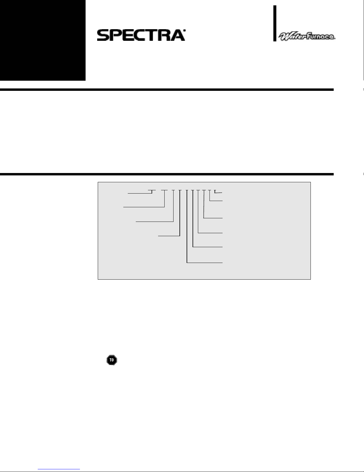
Model
Nomenclature
Model Nomenclature 1
Safety Considerations 1
Moving and Storage 1
Physical Data 2
General Installation Information 2-5
Boiler/Cooling Tower Closed Loop Systems 5
General Piping 6
System Cleaning and Flushing 6-7
Ground Source Closed Loop Systems 7-8
Open Loop Ground Water Systems 8-9
Desuperheater Connection 9-11
Model Type
SXV = Vertical Unit
SXH = Horizontal Unit
Unit Size
036 = 36,000 BTUH Nominal cooling
at 85°F entering water
Design Vintage
B = Commercial Microprocessor Unit Controls
C = ElectroMechanical Unit Controls
Electrical Characteristics
0 = 208-230/60/1 Commercial
1 = 208-230/60/1 Residential
2 = 265-277/60/1 Commercial
3 = 208-230/60/3 Commercial
4 = 460-480/60/3 Commercial
5 = 575-600/60/3 Commercial
036 C C1
0X0TSXV
L
Initial Desuperheater Start Up 11
Electrical Connections 11-12
Unit Electrical Data 13
Unit Operating Pressures 13
Wiring Schematic 14-15
Thermostat 16
Blower Performance Data 16
Unit Start Up 17-18
Preventive Maintenance 18-19
Troubleshooting 19
Replacement Procedures 19
Non-Standard Options
Discharge Air Options
T = Top (Vertical)
E = End (Horizontal)
S = Side (Horizontal)
Return Air Options
L = Left return
R = Right return
Coax Options
C = Copper
N = Cupronickel
Cabinet
0 = Painted Steel Cabinet
1 =Galvanized Steel Cabinet
Hot Water Options
0 = None
1 = Hot Water Generation W/Pump (Residential)
2 = Hot Water Generation Without/Pump (Commercial)
Safety
Considerations
Moving and
Storage
Installation and servicing of air conditioning equipment can be hazardous due to system
pressure and electrical components. Only trained and qualified service personnel should install,
repair or service air conditioning equipment.
Untrained personnel can perform basic maintenance functions of cleaning coils and cleaning
and replacing filters. All other operations should be performed by trained service personnel. When
working on air conditioning equipment, observe precautions in the literature, tags and labels
attached to the unit and other safety precautions that may apply.
Follow all safety codes. Wear safety glasses and work gloves. Use quenching cloth for brazing
operations. Have fire extinguisher available for all brazing operations.
WARNING: Before performing service or maintenance operations on system, turn off
main power switches to indoor unit. Turn off accessory heater power switch if applicable.
Electrical shock could cause personal injury.
Move units in the normal “up” orientation as indicated by the arrows on each carton. Horizontal
units may be moved and stored per the information on the carton, “Do not stack more than 3 units
in total height.” Vertical units are not to be moved, but may be stored one upon another at a
maximum height of 2 units. When the equipment is received, all items should be carefully checked
against the bill of lading to be sure all crates and cartons have been received. Examine units for
shipping damage, removing the units from the cartons if necessary. Units in question should also
be internally inspected. If any damage is noted, the carrier should make the proper notation on the
delivery receipt, acknowledging the damage.
SPECTRA COMMERCIAL AND RESIDENTIAL INSTALLATION GUIDE
0
Physical
Data
Fan Wheel 6 X 8 6 X 8 9 X 7 9 X 7 9 X 7 9 X 7 9 X 7 10 X 10 10 X 10 11 X 10 11 X 10
PSC Fan Motor HP - # of Speeds 1/10 - 4 1/10 - 4 1/6 - 3 1/6 - 3 1/5 - 3 1/3 - 3 1/2 - 3 1/2 - 3 1/2 - 3 3/4 - 3 1.0 - 3
Compressor Rotary Rotary Rotary Rotary Recip Recip Recip Recip Recip Scroll Scroll
R22 (oz.) 28.0 36.0 38.0 43.0 63.0 66.0 65.0 95.0 86.0 98.0 98.0
Vertical
Air Coil Dimensions (in.) 12 x 16 16 x 16 19 x 20 19 x 20 24 x 20 24 x 20 27 x 20 28 x 25 28 x 25 32 x 25 36 x 25
Air Coil Face Area (sq ft.) 1.3 1.8 2.6 2.6 3.3 3.3 3.8 4.9 4.9 5.6 6.3
Air Coil # of Rows 3 3 3 3 3 3 3333 3
Filter - 1" Throwaway (Std.) 16 X 20 16 X 20 18 X 24 18 X 24 24 X 24 24 X 24 2-14 X 24 2 -14 X 30 2 - 14 X 3
Filter - 1" Electrostatic (opt.) EAF1620 EAF1620 EAF1824 EAF1824 EAF2424 EAF2424 EAF2428 EAF2830 EAF2830 EAF3032 EAF3036
Weight 150 163 180 183 265 270 290 326 344 401 428
Horizontal
Air Coil Dimensions (in.) 12 x 16 16 x 16 18 x 21 18 x 21 18 x 27 18 x 27 18 x 30 20 x 35 20 x 35 20 x 40 20 x 45
Air Coil Face Area (sq in.) 1.3 1.8 2.6 2.6 3.4 3.4 3.8 4.9 4.9 5.6 6.3
Air Coil # of Rows 3 3 3 3 3 3 3333 3
Filter - 1" Throwaway (Std.) 16 x 20 16 x 20 18 x 24 18 x 24 2-18 x 18 2-18 x 18 2-18 x 18 1 - 20 x 12 1 - 20 x 12 1 - 18 x 20 2 - 24 x 20
Filter - 1" Electrostatic (opt.) EAF1620 EAF1620 EAF1824 EAF1824 EAF1836 EAF1836 EAF1836 EAF2037 EAF2037 EAF2042 EAF2048
Weight 155 164 194 204 270 272 286 343 347 431 458
General
Installation
Information
MODEL SX010 SX013 SX016 SX019 SX024 SX030 SX036 SX042 SX048 SX058 SX068
2 - 10 X 30 3 - 12 X 30
1 - 12 X 30
1 - 20 x 25 1 - 20 x 25 1 - 24 x 20
Unit Location
Locate the unit in an indoor area that allows easy removal of the filter and access
panels, and has enough space for service personnel to perform maintenance or repair.
Provide sufficient room to make water, electrical and duct connection(s). If the unit is
located in a confined space, such as a closet, provisions must be made for return air to
freely enter the space by means of a louvered door, etc. Any access panel screws that
would be difficult to remove after the unit is installed should be removed prior to setting the
unit. On horizontal units, allow adequate room below the unit for a condensate drain trap
and do not locate the unit above supply piping. These units are not approved for outdoor
installation and must be installed inside the structure being conditioned.
within 45
CAUTION:
°
-95°F and up to 75% relative humidity.
Do not locate in areas where ambient conditions are not maintained
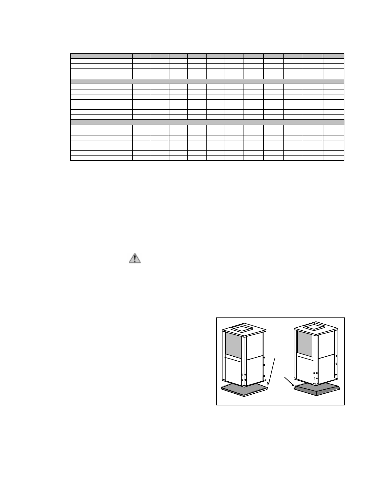
Setting the Vertical Units
Vertical units are available in left or right air return configurations. Top flow vertical units
should be mounted level on a vibration absorbing pad slightly larger than the base to
provide isolation between the unit and the floor. It is not necessary to anchor the unit to the
floor (see figure 1). Bottom flow units
should be mounted level and sealed
well to floor to prevent air leakage.
If left side unit access will be
limited after installation, remove the
two left side control box mounting
screws before setting the unit (leave
the two front mounting screws intact).
Vibration
Absorbing
Mesh
Air
Pad
This will allow the control box to be
removed with only the two front
mounting screws for future service.
Figure 1– Vertical Unit Mounting
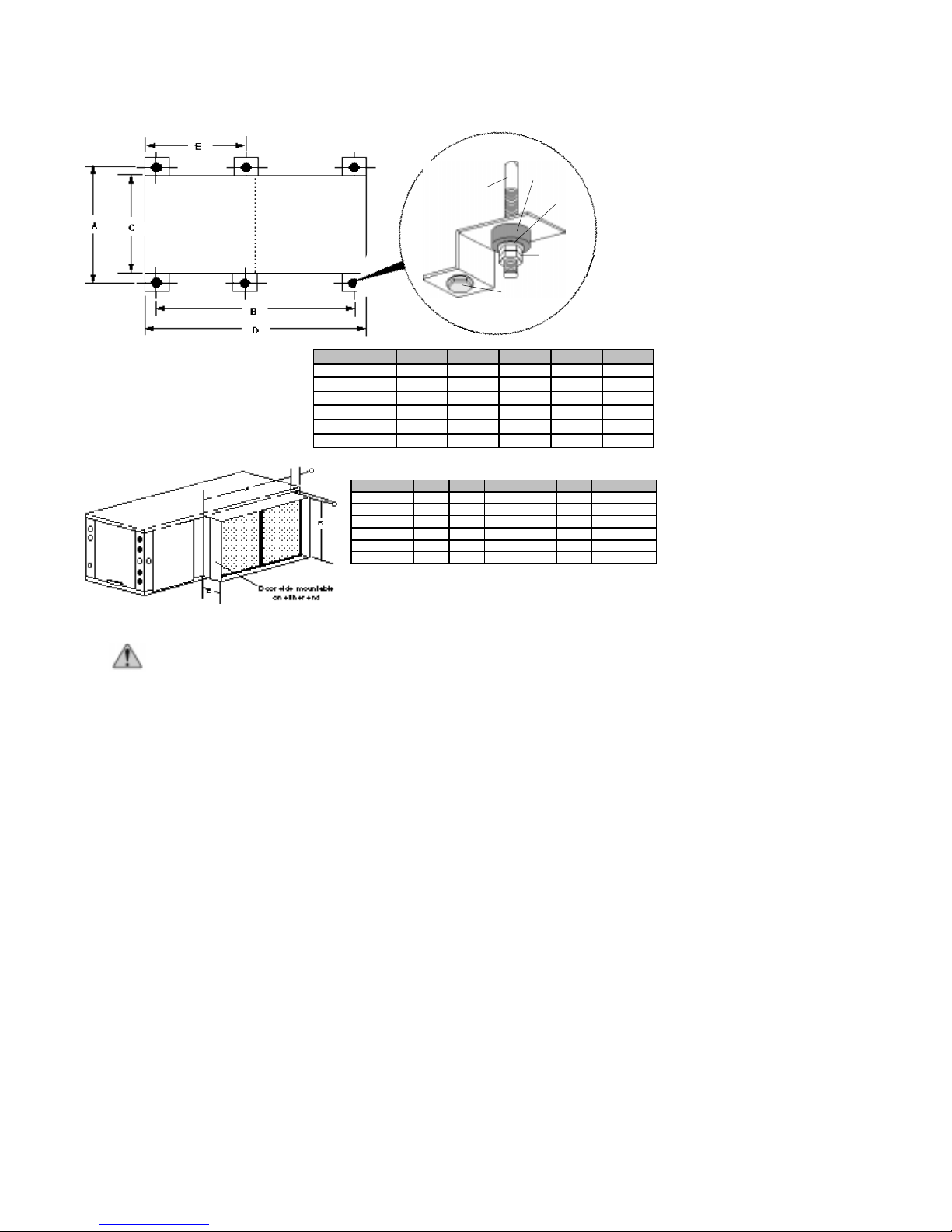
Setting the Horizontal Units
Horizontal units are available with side or end discharge and may be field converted
from one to the other by replacing the discharge panel. The new panel must be ordered.
Horizontal units are normally suspended from a ceiling by four 3/8” diameter threaded rods
(6 on SXH042-068). The rods are usually attached to the unit corners by hanger bracket
kits furnished with each unit.
2
SPECTRA COMMERCIAL AND RESIDENTIAL INSTALLATION GUIDE
3/8" Threaded Rod
Compressor
Section
Air Handler
Figure 2A– Hanger Location and Assembly
Section
MODEL A B C D E
MODEL
SXH010-013 24.75 42.5 22.5 44 -
SXH016-019 24.75 51.5 22.5 53 -
SXH022-034 24.75 61.5 22.5 63 -
SXH042-048 27.75 70.5 25.5 72 29.87
SXH058 27.75 75.5 25.5 77 29.87
SXH068 27.75 80.5 25.5 82 29.87
MODEL A B C D E MODEL NO.
SX010-013 20.2 16.2 1.8 0.5 5.5 DCH1620
SX016-019 24.2 18.2 1.2 0.5 5.5 DCH1824
SX024-030 36.2 18.2 1.2 0.5 5.5 DCH1836
SX042-048 37.2 20.2 1.8 0.5 5.5 DCH2037
SX058 42.2 20.2 1.8 0.5 5.5 DCH2042
SX068 48.2 20.2 1.3 0.5 5.5 DCH2048
1" duct connection provided
Air tight construction
(by others)
Bolt and
Lockwasher
Vibrator
Isolator
Hex Nuts
(by others)
Washer
Figure 2B– Optional Filter Rack
CAUTION: Do not use rods smaller than 3/8” diameter since they may not be
strong enough to support the unit. The rods must be securely anchored to the ceiling.
Lay out the threaded rods per the dimensions in Figure 2A, and assemble the hangers to
the unit as shown. Securely tighten the brackets to the unit using the weldnuts located on the
underside of the bottom panel. When attaching the hanger rods to the bracket, a double nut
is required since vibration could loosen a single nut. The unit should be pitched approximately 1/4” towards the drain in both directions, to facilitate condensate removal (see Figure
3B, on page 4). Use only the bolts provided in the kit. The use of longer bolts could damage
internal parts.
Some residential applications require an attic floor installation of horizontal units. In this
case, the unit is set in a full size secondary drain pan on top of vibration absorbing mesh.
The secondary drain pan prevents possible condensate overflow or water leakage damage to
the ceiling. The secondary drain pan is usually placed on a plywood base isolated from the
ceiling joists by additional layers of vibration absorbing mesh.
Duct System
An air outlet collar is provided on vertical top flow units and all horizontal units to facilitate
a duct connection (vertical bottom flow units have no collar). A flexible connector is recommended for discharge and return air duct connections on metal duct systems. Uninsulated
duct should be insulated with a minimum of one-inch duct insulation. Application of the unit to
uninsulated ductwork in an unconditioned space is not recommended as the unit’s performance will be adversely affected.
3
SPECTRA COMMERCIAL AND RESIDENTIAL INSTALLATION GUIDE
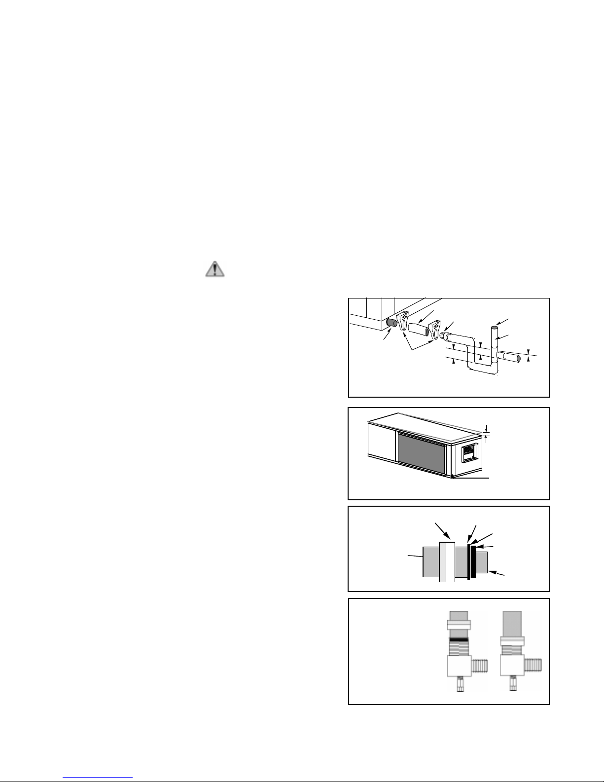
1.5"
1.5"
Vent (if needed)
3/4" PVC
3/4" barb to
glue adapter *
1/8" per foot
Clear PVC hose *
Plastic Hose Clamp *
Copper tube stub
For vertical bottom flow units, cut the air discharge floor opening at least 1/2" larger than
unit air outlet.
Protect opening edges in combustible flooring with sheet metal overwrap.
Discharge air only into a suitable supply duct system and do not locate registers or openings directly under unit air outlet.
If the unit is connected to existing ductwork, a previous check should have been made
to assure that the duct has the capacity to handle the air required for the unit application. If
ducting is too small, as in the replacement of heating only systems, larger ductwork should
be installed. All existing ductwork should be checked for leaks and repairs.
The duct system should be sized to handle the design airflow quietly.
To maximize
sound attenuation of the unit blower, the supply and return plenums should include internal
duct liner of glass fiber or be of ductboard construction for the first few feet.
If air noise or
excessive air flow is a problem, the blower speed can be changed. See the Blower Performance and Fan Speed sections for further instructions.
before connecting ductwork.
Water Piping
water connections are swivel piping
fittings that accept a 1" Male Pipe
Thread (MPT) (see Figure 4A). The
swivel connector has a rubber gasket
seal similar to a garden hose gasket,
which when mated to the flush end of
any 1" threaded pipe provides a leakfree seal without the need for thread
sealing tape or compound. Check to
insure that the rubber seal is in the
swivel connector prior to attempting
any connection. The rubber seals are
shipped attached to one of the swivel
connections on the unit. DO NOT
OVERTIGHTEN or leaks may occur.
ground loop system, mate the brass
connector (supplied in CK4L & CK4S
connector kits) against the rubber
gasket in the swivel connector, and
thread the female locking ring onto
the pipe threads, while maintaining
the brass connector in the desired
direction (see Figure 4B). Tighten the
connectors by hand to provide a leak
proof joint. When connecting to an
open loop (ground water) system,
thread any 1" MPT fitting (PVC or
copper) into the swivel connector and
tighten in the same manner as noted
4
above. The open and closed loop
piping system should include pressure/temperature taps for serviceability.
CAUTION:
Be sure to remove the foam shipping material from the blower throat
All Residential Spectra source
To make the connection to a
Figure 3A - Horizontal Drain Connection
*Included with unit
Figure 3B - Uni Pitch for Drain
Threaded Female
Locking Ring
This side is soldered
to the unit tubing
Retaining Ring
Figure 4A
Figure 4B - The
Female Locking Ring is
threaded onto the pipe
threads which holds the
male pipe end against
the gasket, and seals
the joint. HAND
TIGHTEN ONLY! DO
NOT OVERTIGHTEN!
1/4” Pitch
Drain
Brass Stop Ring
Gasket Seal
Brass Body

SPECTRA COMMERCIAL AND RESIDENTIAL INSTALLATION GUIDE
Never use flexible hoses smaller than 1" inside diameter on the unit and limit hose
length to 10 ft. per connection. Check carefully for water leaks.
Water Quality
The unit may be ordered with either a copper or a cupronickel coaxial heat exchanger.
Copper is adequate for closed loop and open loop ground water systems which are not high
in mineral content. In conditions anticipating moderate scale formation or in brackish water,
a cupronickel heat exchanger is recommended. In ground water situations where scaling
could be heavy or where biological growth such as iron bacteria will be present, a closed
loop system is recommended. Ground water unit heat exchanger coils may over a period of
time lose heat exchange capabilities due to a buildup of mineral deposits inside. These can
be cleaned, but only by a qualified service mechanic as special solutions and pumping
equipment are required. Desuperheater coils can likewise become scaled and possibly
plugged. In areas with extremely hard water, the homeowner should be informed that the
heat exchanger may require occasional acid flushing.
Freeze Protection (Commercial Microprocessor Only)
Set the freeze protection switch SW1 #2 on the microprocessor board for applications
using a closed loop antifreeze solution to" LOOP". On applications using an open loop/
ground water system or non freeze protected loop, set to "WELL" (the factory setting).
Condensate Drain
On vertical units, the internal condensate drain assembly consists of a drain tube which
is connected to the drain pan, a 3/4" PVC female adapter and a flexible connecting hose.
The female adapter may exit either the front or the side of the cabinet. The adapter should
be glued to the field-installed PVC condensate piping. On vertical units, a condensate hose
is inside all cabinets as a trapping loop; therefore, an external trap is not necessary. On
horizontal units, a copper stub is provided for condensate drain piping connection. An
external trap is required (see Figure 3A page 4). If a vent is necessary, an open stand pipe
may be applied to a tee in the field-installed condensate piping.
Air Coil
To obtain maximum performance the air coil should be cleaned before start up. A 10%
solution of dishwasher detergent and 90% water is recommended for both sides of coil. A
thorough water rinse should follow.
Boiler/Cooling Tower
The water loop is usually maintained between 60°F and 90°F (Spectra units allow 25°F 110°F EWT) for proper heating and cooling operation. see Figure 5 page 6 for a typical
installation.
To reject excess heat from the water loop, the use of a closed circuit evaporative cooler
or an open type cooling tower with a secondary heat exchanger between the tower and the
water loop is recommended. If an open type cooling tower is used without a secondary heat
exchanger, continuous chemical treatment and filtering of the water must be performed to
ensure the water is free from damaging materials.
Boiler/Cooling
Tower Closed
Loop Systems
CAUTION: Water piping exposed to outside temperatures may be subject to freezing.
NOTE:
#4 to the "WELL" position.
For Boiler/Cooling Tower Systems with no antifreeze solution, set SW1-Switch
5
SPECTRA COMMERCIAL AND RESIDENTIAL INSTALLATION GUIDE
Figure 5- Closed Loop Cooler/Boiler System
Flexible Duct
Insulate supply
plenum and use at
least a 90° elbow
to reduce noise
General
Piping
Electric heat
assembly
(optional)
Collar
3/8”
Threaded rods
(6) on AT040-046
Drain per
Figure 2 On air
coil, side or end
Disconnects
Hanging
Brackets
(included)
Line Voltage
To Line
Power
To Thermostat
Drain per
Figure 2
P/T Plugs
Boiler/Cooling
Tower Loop
Water Piping Connections
Units should not be connected to the supply and return piping until the water system
has been cleaned and flushed completely. Supply and return water connections are
standard female pipe thread. Never use flexible hoses with an inside pipe diameter that is
smaller than the water connections on the unit and limit the hose length to 10 feet or less
per connection. High-pressure flexible hoses provide sound attenuation for both normal unit
operating noise and hydraulic pumping noise. Hard piping can also be brought directly
to the unit although it is not recommended since no vibration or noise attenuation can
be accomplished.
Hose Kits
System
Cleaning and Flushing
Cleaning
and Flushing
6
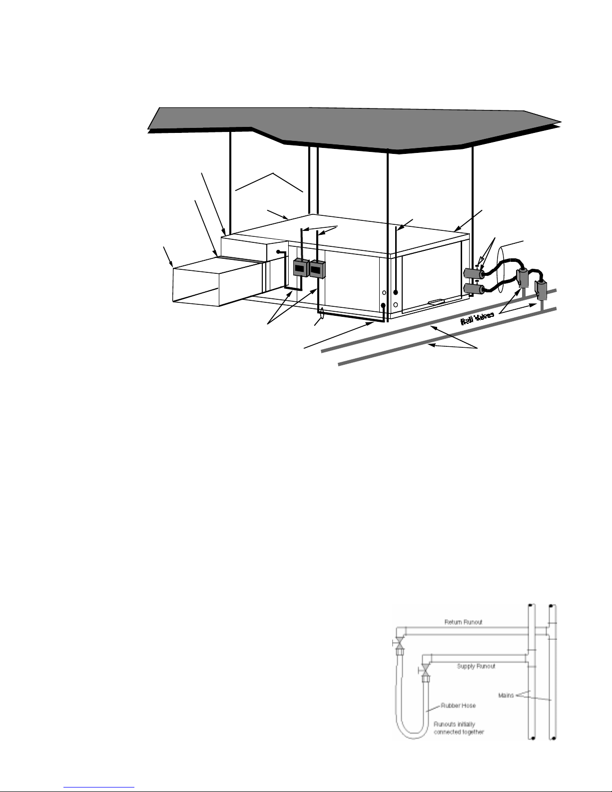
flushed of all dirt and debris.
be connected together at each unit location (This will prevent the introduction of dirt into the
unit, see Figure 6). The system should be filled at the water make-up connection with all
air vents open. After filling, vents should be
closed.
circulator with the pressure reducing valve
makeup open. Vents should be checked in
sequence to bleed off any trapped air and to
verify circulation through all components of the
system.
the contractor should check and repair any
leaks found in the piping system. Drain(s) at
the lowest point(s) in the system should be
opened for initial flush and blowdown, making
sure water fill valves are set at the same rate.
Prior to start up of any heat pump, the water circulating system must be cleaned and
If the system is equipped with water shutoff valves, the supply and return runouts must
Figure 6 - Flushing with Water Shutoff
The contractor should start the main
Valve Equipped Systems
As water circulates through the system,
 Loading...