


Envision
Table of contents
 Loading...
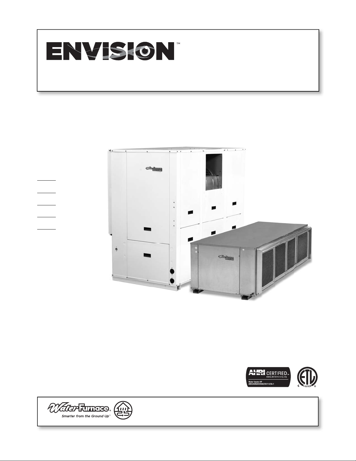
Installation Information
Water Piping Connections
Electrical Connections
Startup Procedures
Preventive Maintenance
IM1021ANA 01/15
Envision 7-25 Tons Installation Manual
Water Source/Geothermal Heat Pump
7 to 25 Tons

ENVISION 7-25 TONS INSTALLATION MANUAL
Table of Contents
Model Nomenclature. . . . . . . . . . . . . . . . . . . . . . . . . . . . . . . . . . . . . . . . . . . . . . . . . . . . . . . . . . . 4
General Installation Information . . . . . . . . . . . . . . . . . . . . . . . . . . . . . . . . . . . . . . . . . . . . . . . . . 5
Vertical Dimensions. . . . . . . . . . . . . . . . . . . . . . . . . . . . . . . . . . . . . . . . . . . . . . . . . . . . . . . . . . .6-7
Horizontal Dimensions . . . . . . . . . . . . . . . . . . . . . . . . . . . . . . . . . . . . . . . . . . . . . . . . . . . . . . . . . 8
Installing Horizontal Units . . . . . . . . . . . . . . . . . . . . . . . . . . . . . . . . . . . . . . . . . . . . . . . . . . . . 9-10
Installating Vertical Units . . . . . . . . . . . . . . . . . . . . . . . . . . . . . . . . . . . . . . . . . . . . . . . . . . . . . . . 11
Water Quality . . . . . . . . . . . . . . . . . . . . . . . . . . . . . . . . . . . . . . . . . . . . . . . . . . . . . . . . . . . . . . . . .12
System Cleaning and Flushing. . . . . . . . . . . . . . . . . . . . . . . . . . . . . . . . . . . . . . . . . . . . . . . . . . .13
Electrical Connections . . . . . . . . . . . . . . . . . . . . . . . . . . . . . . . . . . . . . . . . . . . . . . . . . . . . . . . . .14
Electrical Data . . . . . . . . . . . . . . . . . . . . . . . . . . . . . . . . . . . . . . . . . . . . . . . . . . . . . . . . . . . . . . . . 15
Blower Performance Data . . . . . . . . . . . . . . . . . . . . . . . . . . . . . . . . . . . . . . . . . . . . . . . . . . . 16-25
Wiring Schematics. . . . . . . . . . . . . . . . . . . . . . . . . . . . . . . . . . . . . . . . . . . . . . . . . . . . . . . . . 26-27
Optional FX10 Microprocessor Control . . . . . . . . . . . . . . . . . . . . . . . . . . . . . . . . . . . . . . . .28-37
Blower Drive Sheaves . . . . . . . . . . . . . . . . . . . . . . . . . . . . . . . . . . . . . . . . . . . . . . . . . . . . . . . . . 38
Unit Startup . . . . . . . . . . . . . . . . . . . . . . . . . . . . . . . . . . . . . . . . . . . . . . . . . . . . . . . . . . . . . . . . . 39
Operating Parameters. . . . . . . . . . . . . . . . . . . . . . . . . . . . . . . . . . . . . . . . . . . . . . . . . . . . . . . . . 40
Pressure Drop. . . . . . . . . . . . . . . . . . . . . . . . . . . . . . . . . . . . . . . . . . . . . . . . . . . . . . . . . . . . . . . . 40
Startup/Troubleshooting Form . . . . . . . . . . . . . . . . . . . . . . . . . . . . . . . . . . . . . . . . . . . . . . . . . .41
Preventive Maintenance . . . . . . . . . . . . . . . . . . . . . . . . . . . . . . . . . . . . . . . . . . . . . . . . . . . . . . . 42
Replacement Procedures . . . . . . . . . . . . . . . . . . . . . . . . . . . . . . . . . . . . . . . . . . . . . . . . . . . . . . 42
ENVISION 7-25 TONS INSTALLATION MANUAL
4
Model Nomenclature
NL
1-2 3-5 6 7 8
Model Type
NL – Envision Series
(Low Temp)
NX – Envision Series
(Extended Range)
Unit Capacity (MBTUH)
080, 095, 120, 160
180, 240, 300
Discharge Configuration
T – Top Upflow (Vertical)
E – End Discharge (Horizontal)
S – Discharge Side (Horizontal)
Return Air Configuration
L – Left
R – Right
Voltage
3 – 208-230/60/3
4 – 460/60/3
5 – 575/60/3
Future Option
0 – Future
Blower Options
A – Standard Static, Standard Motor
B – Low Static, Standard Motor
1
C – High Static, Standard Motor
2
D – Standard Static, Large Motor
2,3
E – High Static, Large Motor
3
Water Coil Option
C – Copper
N – CuproNickel
Vintage
* - Factory Use Only
Non-Standard Options
SS – Standard
QP – 2" MERV 13 Filter
SF – Stainless Steel Drain Pan
4
SG – 2" MERV 13 Filter, Stainless Steel Drain Pan
4
Air Coil/Insulation Option
3 – Uncoated
4 – AlumiSeal
TM
Control Option
4 – FX10 Standard without Communication
5 – FX10 with Open N2 Communication
6 – FX10 with Lonworks Communication
7 – FX10 with BacNet Communication
8 – FX10 Standard with User Interface
9 – FX10 with Open N2 & User Interface
0 – FX10 with Lonworks & User Interface
3 – FX10 with BacNet & User Interface
Water Control Option
N – None
V – Two-Way Valve
Hot Gas Bypass/Reheat Option
N – None
G – Hot Gas Bypass
R – Hot Gas Reheat
B – Hot Gas Bypass w/Hot Gas Reheat
Sound Kit Option
A – None
B – Sound Kit
Rev.: 14 November 2014D
91011 13
120 T L 3 0 A C A N
12
N
14
4
15
1
16
SS
17-18
*
19
Notes:
1 – Not available on vertical NL/NX095, 180, horizontal NL/NX080
2 – Not available on vertical NL/NX080, 160
3 – Not available on horizontal NL/NX120, vertical NL/NX300
4 – Not available on vertical NL/NX160-300. Stainless steel is standard on vertical NL/NX160-300
COMMERCIAL
ENVISION 7-25 TONS INSTALLATION MANUAL
5
WARNING: Before performing service or maintenance operations on a system, turn off main power switches to
the indoor unit. If applicable, turn off the accessory heater power switch. Electrical shock could cause personal
injury.
Installing and servicing heating and air conditioning equipment can be hazardous due to system pressure and electrical
components. Only trained and qualified service personnel should install, repair or service heating and air conditioning
equipment. Untrained personnel can perform the basic maintenance functions of cleaning coils and cleaning and
replacing filters. All other operations should be performed by trained service personnel. When working on heating and
air conditioning equipment, observe precautions in the literature, tags and labels attached to the unit and other safety
precautions that may apply.
Follow all safety codes. Wear safety glasses and work gloves. Use a quenching cloth for brazing operations and have a fire
extinguisher available.
Moving and Storage
Move units in the normal “up” orientation. Horizontal units may be moved and stored per the information on the packaging.
Do not stack more than three units in total height. Vertical units may be stored one upon another to a maximum height
of two units. Do not attempt to move units while stacked. When the equipment is received, all items should be carefully
checked against the bill of lading to be sure all crates and cartons have been received. Examine units for shipping damage,
removing the units from the packaging if necessary. Units in question should also be internally inspected. If any damage is
noted, the carrier should make the proper notation on the delivery receipt, acknowledging the damage.
Unit Location
Locate the unit in an indoor area that allows for easy removal of the filter and access panels. Location should have enough
space for service personnel to perform maintenance or repair. Provide sufficient room to make water, electrical and duct
connection(s). If the unit is located in a confined space, such as a closet, provisions must be made for return air to freely
enter the space by means of a louvered door, etc. Any access panel screws that would be difficult to remove after the
unit is installed should be removed prior to setting the unit. On horizontal units, allow adequate room below the unit for
a condensate drain trap and do not locate the unit above supply piping. Care should be taken when units are located
in unconditioned spaces to prevent damage from frozen water lines and excessive heat that could damage electrical
components.
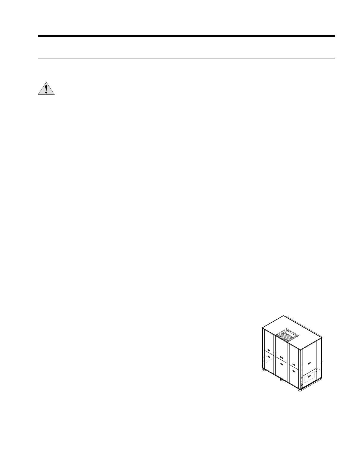
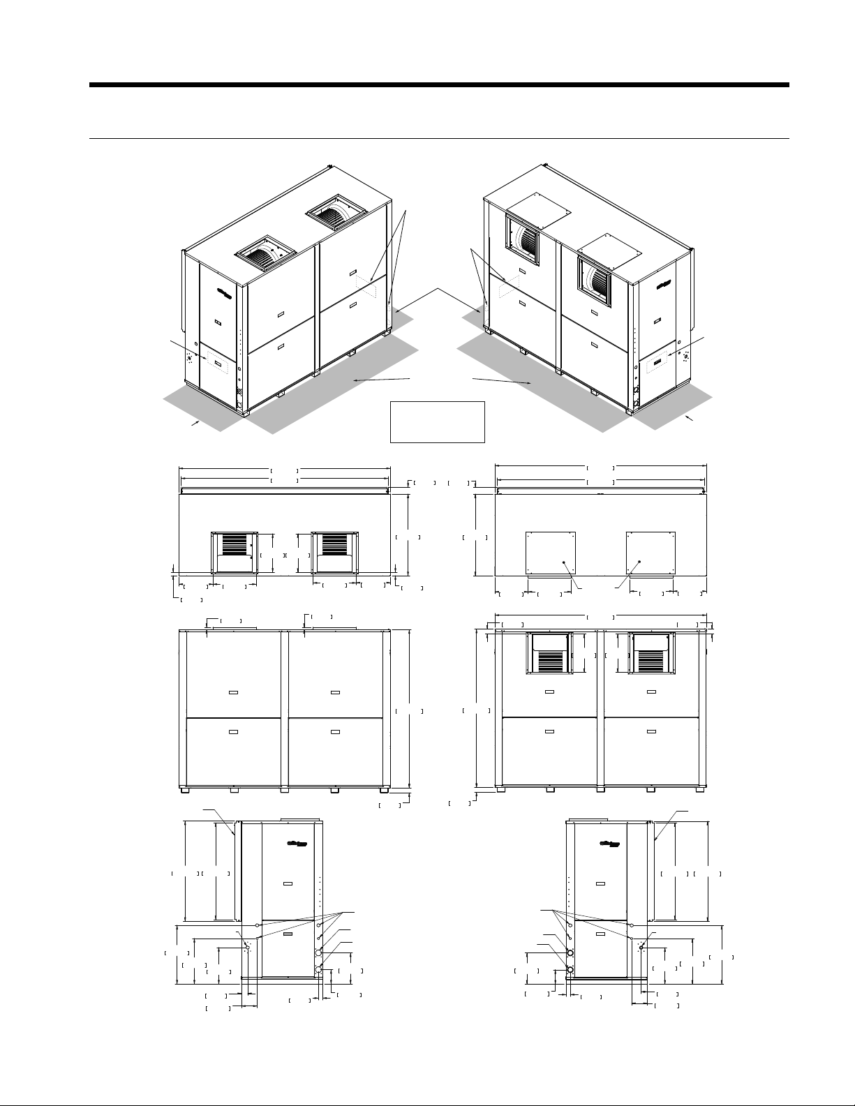
Installing Vertical Units
Prior to setting the unit in place, remove and discard the compressor hold down
shipping bolt located at the front of the compressor mounting bracket.
Vertical units are available in left or right air return configurations. Top flow vertical
units should be mounted level on a vibration absorbing pad slightly larger than the
base to provide isolation between the unit and the floor. It is not necessary to anchor
the unit to the floor (see right).
Safety Considerations
General Installation Information
Figure 1: Vertical Unit Mounting
(NXV/NLV 080-300)
ENVISION 7-25 TONS INSTALLATION MANUAL
6
CONTROL BOX
RIGHT RETURN
CONTROL BOX AND WATER
LEFT RETURN
2’ PRIMARY
SERVICE ACCESS
FOR LEFT RETURN
2’ PRIMARY
CONTROL BOX
RIGHT RETURN
SERVICE ACCESS
FOR RIGHT RETURN
2’ SECONDARY
SERVICE ACCESS
CONTROL BOX
AND WATER
LEFT RETURN
TOP DISCHARGE
2’ PRIMARY
SERVICE ACCESS
FOR LEFT RETURN
2’ PRIMARY
SERVICE ACCESS
FOR RIGHT RETURN
2’ SECONDARY
SERVICE ACCESS
SIDE DISCHARGE
56 in
[142.2 cm]
2 in [5.1 cm]
1 in [2.5 cm]
2 in [5.1 cm]
18.1 in [46 cm]
1.8 in [4.6 cm]
56 in
[142.2 cm]
22.6 in
[57.4 cm]
TOP PANEL
COVER
58.1 in [147.6 cm]
61.3 in [155.7 cm]
34.1 in
[86.6 cm]
2.9 in
[7.4 cm]
16.1 in
[40.9 cm]
TOP VIEW
Left or Right Return
SIDE VIEW
Left or Right Return
34.1 in
[86.6 cm]
58.1 in [147.6 cm]
61.3 in [155.8 cm]
21.6 in
[54.9 cm]
18.1 in
[46.0 cm]
1.42 in
[3.6 cm]
16.1 in
[40.9 cm]
2.9 in
[7.4 cm]
15.6 in
[39.6 cm]
12.5 in [31.8 cm]
36.3 in
[92.2 cm]
2.6 in [6.6 cm]
DRAIN CONNECTION
WATER OUT
WATER IN
ELECTRICAL
CONNECTIONS
ELECTRICAL
CONNECTIONS
AIR COILS
34.4 in
[87.4 cm]
4.0 in [10.2 cm]
2.2 in [5.6 cm]
10.1 in [25.7 cm]
2.0 in
[5.1 cm]
2.2 in
[5.6 cm]
7.2 in
[18.3 cm]
LEFT RETURN RIGHT RETURN
15.6 in
[39.6 cm]
4.0 in [10.2 cm]
2.2 in [5.6 cm]
10.1 in [25.7 cm]
2.2 in
[5.6 cm]
12.5 in [31.8 cm]
36.3 in
[92.2 cm]
2.6 in [6.6 cm]
DRAIN CONNECTIO
N
WATER OUT
WATER IN
AIR COILS
34.4 in
[87.4 cm]
7.2 in
[18.3 cm]
2.0 in
[5.1 cm]
TOP OR SIDE DISCHARGE
Legend
AP = Alternate Service Panel
BP = Blower Service Panel
CP = Control Access Panel
CMP = Compressor Service Panel
AP
CMP
AP
CMP
CPCP
CP CP
REV 2/11/0
8
Vertical Dimensions
7-10 Tons
ENVISION 7-25 TONS INSTALLATION MANUAL
7
LEFT RETURN
6.0 in
15.2 cm
13.0 in
33.0 cm
15.2 in
38.7 cm
19.0 in
48.2 cm
24.5 in
62.2 cm
18.0 in
45.7 cm
18.0 in
45.7 cm
16.0 in
40.6 cm
16.0 in
40.6 cm
16.0 in
40.6 cm
16.0 in
40.6 cm
1.5 in
3.7 cm
1.5 in
3.7 cm
2.0 in
5.1 cm
2.0 in
5.1 cm
34.0 in
86.4 cm
14.2 in
36.1 cm
14.2 in
36.1 cm
2.6 in
6.5 cm
6.5 in
16.5 cm
88.1 in
223.8 cm
RIGHT RETURN
TOP DISCHARGE
SIDE DISCHARGE
88.1 in
223.8 cm
86.3 in
219.1 cm
1.0 in
2.5 cm
66.0 in
167.5 cm
2.0 in
5.1 cm
1.0 in
2.5 cm
34.0 in
86.4 cm
2.9 in
7.3 cm
86.3 in
219.1 cm
88.1 in
223.8 cm
18.0 in
45.8 cm
13.8 in
35.1 cm
18.0 in
45.8 cm
13.8 in
35.1 cm
TOP PANEL
COVER
2.9 in
7.3 cm
66.0 in
167.5 cm
2.0 in
5.1 cm
DRAIN CONNECTION
ELECTRICAL
CONNECTIONS
40.4 in
102.6 cm
41.8 in
106.2 cm
AIR COILS
AIR COILS
41.8 in
106.2 cm
40.4 in
102.6 cm
15.2 in
38.7 cm
19.0 in
48.2 cm
24.5 in
62.2 cm
2.6 in
6.5 cm
6.5 in
16.5 cm
6.0 in
15.2 cm
13.0 in
33.0 cm
1.7 in
4.4 cm
1.7 in
4.4 cm
DRAIN CONNECTION
WATER OUT
WATER IN
WATER OUT
WATER IN
ELECTRICAL
CONNECTIONS
2’ PRIMARY
SERVICE ACCESS
2’ SECONDARY
SERVICE ACCESS
2’ PRIMARY
SERVICE ACCESS
2’ PRIMARY
SERVICE ACCESS
Legend
AP = Alternate Service Panel
BP = Blower Service Panel
CP = Control Access Panel
CMP = Compressor Service Panel
CONTROL BOX
AND WATER
RIGHT RETURN
CONTROL BOX
AND WATER
LEFT RETURN
CONTROL BOX
LEFT RETURN
AP
CMP
AP
CMP
CP CP
CPCP
CONTROL BOX
RIGHT RETURN
TOP VIEW
L or R Return
SIDE VIEW
L or R Return
TOP OR SIDE DISCHARGE
REV 8/16/07
Vertical Dimensions cont.
13-25 Tons
ENVISION 7-25 TONS INSTALLATION MANUAL
8
RIGHT RETURN
LEFT RETURN
26.2
4.1
15.6
89.0
34.5
90.0
37.3
92.5
7.6
7.615.6
85.91.6
TOP VIEW
26.2
4.1
15.6
89.0
34.5
90.0
37.3
92.5
7.6
7.6 15.6
85.9 1.6
DRAIN CONNECTION
END DISCHARGE
OPTION
15.62
13.5
2.9
6.1
20.1
21.0
END VIEW
DRAIN CONNECTION
END DISCHARGE
OPTION
15.62
2.9
6.1
20.1
21.0
SIDE DISCHARGE
WATER IN
WATER OUT
OPTION
SIDE VIEW
18.6
3.4
29.929.9
24.5
23.5
SIDE DISCHARGE
WATER IN
WATER OUT
OPTION
18.6
3.4
29.929.9
24.5
23.5
13.5
Legend
AP = Alternate Service Panel
BP = Blower Service Panel
CP = Control Access Panel
CMP = Compressor Service Panel
CMP
CMP
CMP
CMP
CPCP
BP BP
2’ PRIMARY
SERVICE ACCESS
2’ SECONDARY
SERVICE ACCESS
2’ SECONDARY
SERVICE ACCESS
REV 4/28/08
Horizontal Dimensions
7-10 Tons
ENVISION 7-25 TONS INSTALLATION MANUAL
9
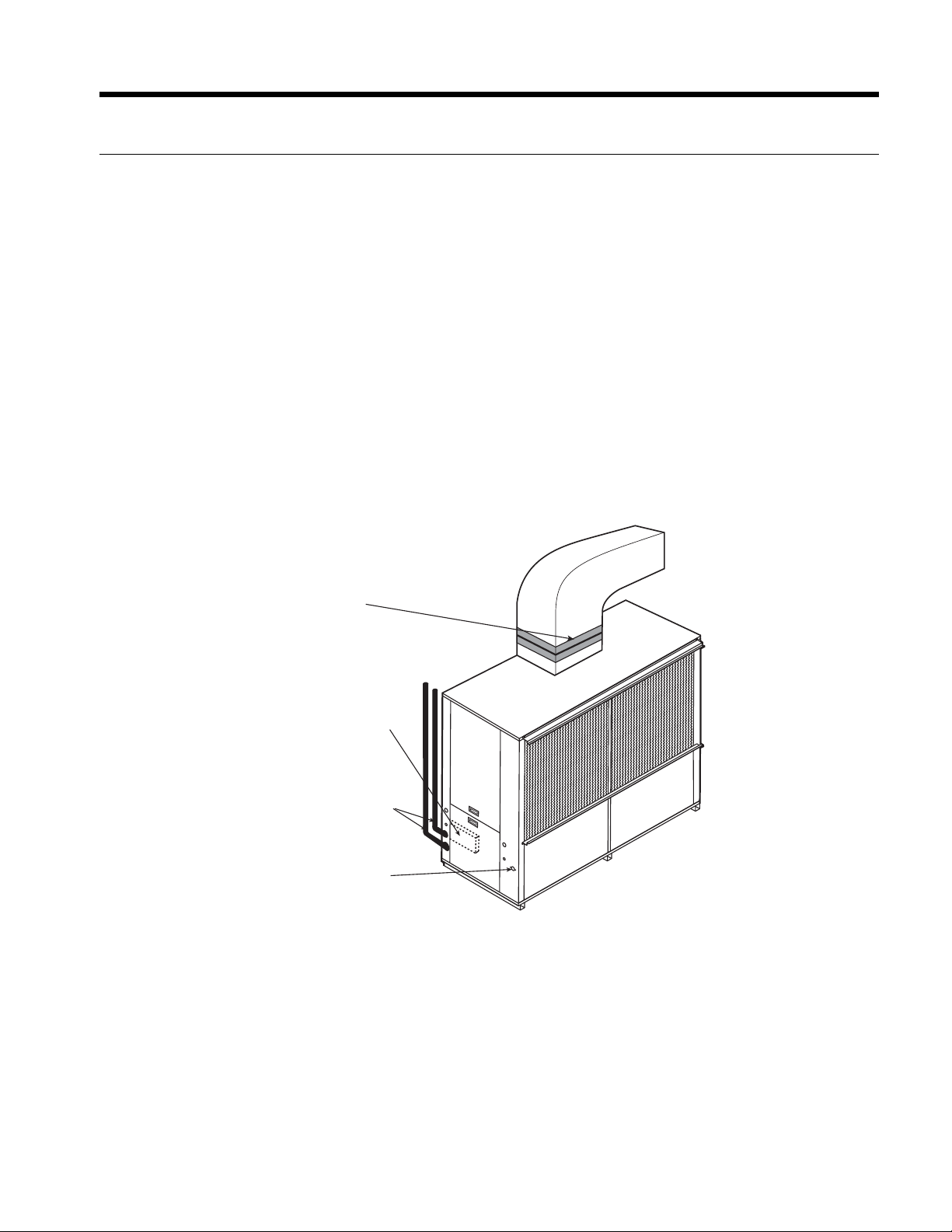
Installing Horizontal Units
Mounting Horizontal Units
Units are available with side or end discharge in left-hand or right-hand return air configurations. Horizontal units are
normally suspended from a ceiling by four 1/2 in. diameter threaded rods. The rods are usually attached to the unit corners
by the bottom panel mounting channel and the mounting grommets furnished with each unit.
CAUTION: Do not use rods smaller than 1/2 in. diameter since they may not be strong enough to support the
unit. The rods must be securely anchored to the ceiling (the units are approximately 800 lbs.).
To p V i e w
90.5
26.244.13
Figure 3: Mounting HardwareFigure 2: Mounting Rod Layout
Ball Valves
Water Loop
Flexible Duct
Collar
1/2”
Threaded Rods
(4)
P/T Plugs
Hose Kits
Insulate supply
plenum and use at
least a 90° elbow
to reduce noise
Condensate
Drain
Connection
Power
Disconnect
Low
Voltage
Isolation
Grommets
(Included)
Figure 1: Typical Horizontal Application
Layout the threaded rods per the dimensions in Figure 2. Assemble the hangers to the unit as shown in Figure 3. Securely
tighten the brackets to the unit. When attaching the hanger rods to the bracket, a double nut is recommended since
vibration could loosen a single nut. The unit should be pitched approximately 1/2 in. towards the drain in both directions, to
facilitate condensate removal.
1/2 in. Threaded Rod
(not included)
Vibration
Isolator
Washer
(not included)
Hex Nuts
(not included)
ENVISION 7-25 TONS INSTALLATION MANUAL
10
1/2'' Pitch
Figure 5: Unit Pitch for DrainFigure 4: Suggested Layout of Condensate
Installing Horizontal Units cont.
ABCD
Front Front Back Back
Model Return / Discharge Left Right Right Left
Left / Side or End 30% 26% 22% 22%
Right / Side or End 26% 30% 22% 22%
Approximate
080 - 120
A
B
C
D
Controls
Horizontal Unit Corner Weight Distribution
Duct System
An air outlet collar is provided on vertical top flow units and all horizontal units to facilitate a duct connection. A flexible
connector is recommended for discharge and return air duct connections on metal duct systems. Uninsulated duct should
be insulated with a minimum of 1-inch duct insulation. Application of the unit to uninsulated ductwork in an unconditioned
space is not recommended as the unit’s performance will be adversely affected.
If the unit is connected to existing ductwork, check the duct system to ensure that it has the capacity to accommodate the
air required for the unit application. If the duct is too small, as in the replacement of heating only systems, larger ductwork
should be installed. All existing ductwork should be checked for leaks and repaired if necessary.
The duct system should be sized to handle the design airflow quietly and efficiently. To maximize sound attenuation of the
unit blower, the supply and return plenums should include an internal duct liner of fiberglass or constructed of ductboard
for the first few feet. On systems employing a sheet metal duct system, canvas connectors should be used between the unit
and the ductwork. If air noise or excessive airflow is a problem, the blower speed can be changed.
Water Piping
The proper water flow must be provided to each unit whenever the unit operates. To assure proper flow, use pressure/tem-
perature ports to determine the flow rate. These ports should be located at the supply and return water connections on the
unit. The proper flow rate cannot be accurately set without measuring the water pressure drop through the refrigerant-to-
water heat exchanger.
All source water connections on commercial units are fittings that accept a male pipe thread (MPT). Insert the connectors
by hand, then tighten the fitting with a wrench to provide a leakproof joint. When connecting to an open loop (groundwa-
ter) system, thread any copper MPT fitting into the connector and tighten in the same manner as described above.
1.5 in.
1.5 in.
3/4 in. PVC tube stub
3/4 in. PVC
Coupling
Vent (if needed)
3/4 in. PVC
1/8 in. per foot
ENVISION 7-25 TONS INSTALLATION MANUAL
11
Control Box
Condensate
Drain
Water Supply
and Return
Connections
Flexible duct
Collar
ACCESS
PAN EL
ACCESS
PANEL
P
A
N
E
L
A
C
C
E
S
S
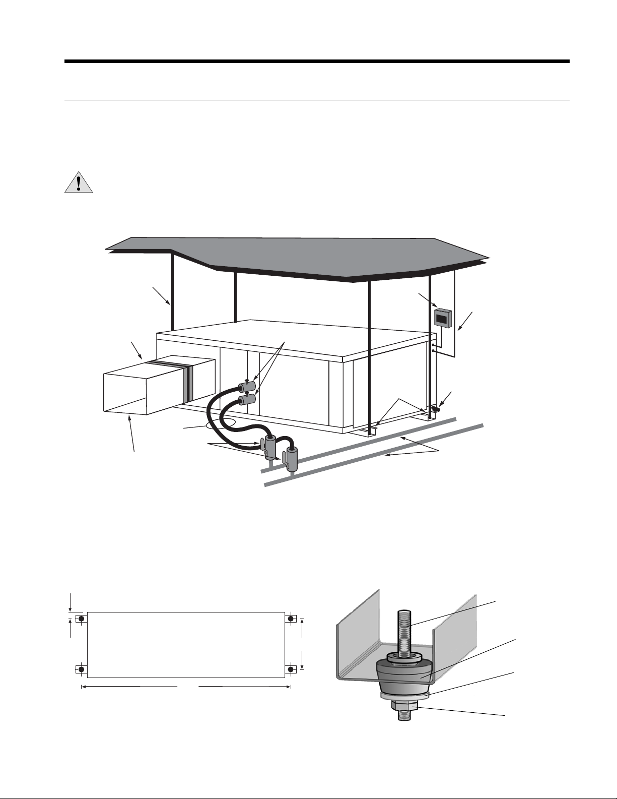
Figure 6: Typical Vertical Application
Installing Vertical Units
Mounting Vertical Units
Units are available with top/side discharge, left-hand or right-hand return air configurations. Vertical units are assembled on
rails which facilitate moving and placement of the units. It is not necessary to anchor the unit to the floor.
Duct System
A supply air duct flange is provided for field installation to facilitate the secure duct connection at the job site. A flexible
connector is recommended for discharge and return air duct connections on metal duct systems to prevent vibration
transmission. It is recommended that all ductwork be insulated with a minimum of 1/2-inch coated insulation. Installation of
the units with uninsulated ductwork in an unconditioned space is not recommended, as the system’s performance will be
adversely affected.
Condensate Drain
In vertical units, the internal condensate drain assembly consists of a flexible drain tube which is attached to the drain pan
and a 3/4-inch (7-10 tons) and 1-inch (13-25 tons) female pipe thread. An external water trap is not required as the drain
tube serves as a trapping loop. The field-installed piping and unit connection must be properly installed and sealed to
prevent water leakage.
ENVISION 7-25 TONS INSTALLATION MANUAL
12
Water Connections
All supply and return water connections are female pipe thread of size specified in physical dimensions. Never use flexible
hoses smaller than separate water connections on the unit and limit hose length to 10 ft. per connection. Check carefully for
water leaks.
Interior Piping
All units are recommended to be connected to supply and return piping in a two-pipe reverse return configuration. A
reverse return system is inherently self-balancing and requires only trim balancing when multiple quantities of units with
different flow and pressure drop characteristics are connected to the same loop. A direct return system may also be made
to work acceptably, but proper water flow balance is more difficult to achieve and maintain.
Supply and return runouts are usually connected to the unit by short lengths of high pressure flexible hose which are sound
attenuators for both unit operating noise and hydraulic pumping noise. One end of the hose should have a swivel fitting to
facilitate removal for service. Hard piping can also be connected directly to the unit although it is not recommended since
no vibration or noise attenuation can be accomplished. The hard piping must have unions to facilitate unit removal (see
figure 1 & 6) for typical application).
Some flexible hose threaded fittings are supplied with sealant compound. If not, apply Teflon tape to assure a tight seal.
Supply and return shutoff valves are required at each unit. The return shutoff valve can be used for balancing and should be
adjusted for proper flow required, or a manual or automatic flow control device should be on the leaving water hose assembly.
No unit should be connected to the supply and return piping until the water system has been cleaned and flushed
completely. After the cleaning and flushing has taken place, the initial connection should have all valves wide open in
preparation for water system filling.
Water Quality Guidelines
In ground water situations where scaling could be heavy or where biological growth such as iron bacteria will be present,
a closed loop system is recommended. The heat exchanger coils in ground water systems may, over a period of time, lose
heat exchange capabilities due to a buildup of mineral deposits inside. These can be cleaned, but only by a qualified service
mechanic, as special solutions and pumping equipment are required. Hot water generator coils can likewise become scaled
and possibly plugged. In areas with extremely hard water, the owner should be informed that the heat exchanger may
require occasional flushing.
Units with cupronickel heat exchangers are recommended for open loop applications due to the increased resistance to
build-up and corrosion, along with reduced wear caused by acid cleaning.
Material Copper 90/10 Cupronickel 316 Stainless Steel
pH Acidity/Alkalinity
7 - 9 7 - 9 7 - 9
Scaling
Calcium and
Magnesium Carbonate
(Total Hardness)
less than 350 ppm
(Total Hardness)
less than 350 ppm
(Total Hardness)
less than 350 ppm
Corrosion
Hydrogen Sulfide
Less than 0.5 ppm (rotten egg
smell appears at 0.5 ppm)
10 - 50 ppm Less than 1 ppm
Sulfates Less than 125 ppm Less than 125 ppm Less than 200 ppm
Chlorine Less than 0.5 ppm Less than 0.5 ppm Less than 0.5 ppm
Chlorides Less than 20 ppm Less than 125 ppm Less than 300 ppm
Carbon Dioxide Less than 50 ppm 10 - 50 ppm 10 - 50 ppm
Ammonia Less than 2 ppm Less than 2 ppm Less than 20 ppm
Ammonia Chloride Less than 0.5 ppm Less than 0.5 ppm Less than 0.5 ppm
Ammonia Nitrate Less than 0.5 ppm Less than 0.5 ppm Less than 0.5 ppm
Ammonia Hydroxide Less than 0.5 ppm Less than 0.5 ppm Less than 0.5 ppm
Ammonia Sulfate Less than 0.5 ppm Less than 0.5 ppm Less than 0.5 ppm
Total Dissolved Solids (TDS) Less than 1000 ppm 1000 - 1500 ppm 1000 - 1500 ppm
LSI Index +0.5 to -0.5 +0.5 to -0.5 +0.5 to -0.5
Iron Fouling
(Biological Growth)
Iron, FE
2
+ (Ferrous)
Bacterial Iron Potential
< 0.2 ppm < 0.2 ppm < 0.2 ppm
Iron Oxide
Less than 1 ppm, above this
level deposition will occur
Less than 1 ppm, above this
level deposition will occur
Less than 1 ppm, above this
level deposition will occur
Erosion
Suspended Solids
Less than 10 ppm and filtered
for max. of 600 mic
ron size
Less than 10 ppm and filtered
for max. of 600 micron size
Less than 10 ppm and filtered
for max. of 600 micron size
Threshold Velocity
(Fresh Water)
< 6 ft/sec < 6 ft/sec < 6 ft/sec
NOTES: Grains = ppm divided by 17
mg/L is equivalent to ppm
2/22/12
Water Quality
ENVISION 7-25 TONS INSTALLATION MANUAL
13
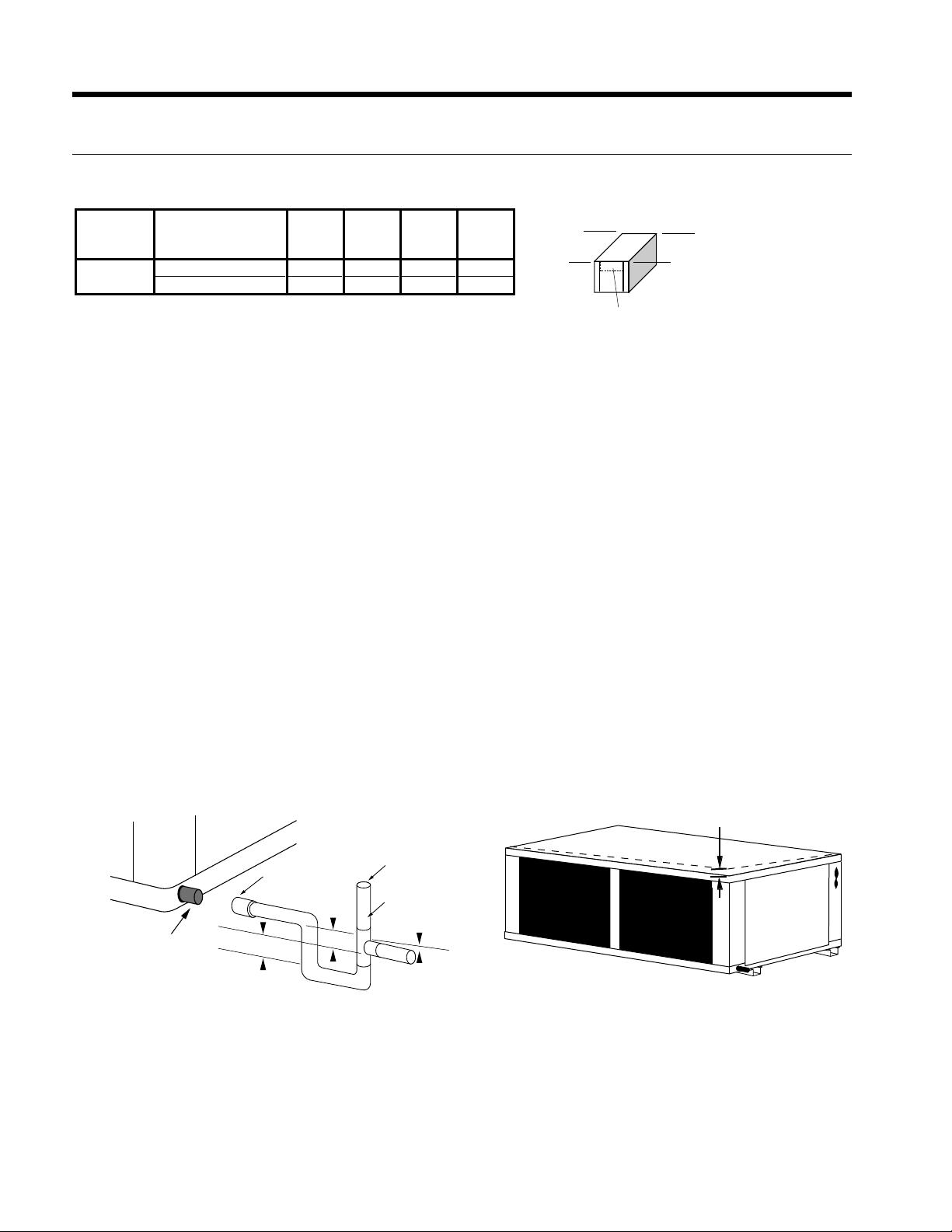
System Cleaning and Flushing
Cleaning and Flushing
Prior to start up of any heat pump, the water circulating system must be
cleaned and flushed of all dirt and debris.
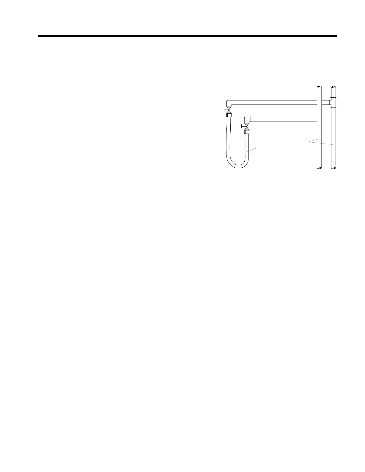
If the system is equipped with water shutoff valves, the supply and
return runouts must be connected together at each unit location (This
will prevent the introduction of dirt into the unit, see Figure 7). The
system should be filled at the water make-up connection with all air
vents open. After filling, vents should be closed.
The contractor should start the main circulator with the pressure
reducing valve makeup open. Vents should be checked in sequence
to bleed off any trapped air and to verify circulation through all
components of the system.
As water circulates through the system, the contractor should check
and repair any leaks found in the piping system. Drain(s) at the lowest
point(s) in the system should be opened for initial flush and blowdown, making sure water fill valves are set at the same
rate. Check the pressure gauge at the pump suction and manually adjust the make-up water valve to hold the same
positive pressure both before and after opening the drain valves. Flushing should continue for at least two hours, or longer
if required, until drain water is clean and clear.
The supplemental heater and/or circulator pump, if used, should be shut off. All drains and vents should be opened to
completely drain the system. Short-circuited supply and return runouts should now be connected to the unit supply and
return connections.
Refill the system with clean water. Test the system water for acidity and treat as required to leave the water slightly alkaline
(pH 7.5 to 8.5). The specified percentage of antifreeze may also be added at this time. Use commercial grade antifreeze
designed for HVAC systems only. Environol™ brand antifreeze is recommended..
Once the system has been filled with clean water and antifreeze (if used), precautions should be taken to protect the
system from dirty water conditions. Dirty water will result in system-wide degradation of performance, and solids may clog
valves, strainers, flow regulators, etc. Additionally, the heat exchanger may become clogged which reduces compressor
service life and can cause premature unit failure.
In boiler/tower application, set the loop control panel set points to desired temperatures. Supply power to all motors
and start the circulating pumps. After full flow has been established through all components including the heat rejector
(regardless of season), air vented and loop temperatures stabilized, each of the units will be ready for check, test and start
up and for air and water balancing.
Ground Source Loop System Checkout
Once piping is completed between the unit pumping system and ground loop, final purging and charging of the loop is
needed. A high pressure pump is needed to achieve adequate flow velocity in the loop to purge air and dirt particles from
the loop itself. Antifreeze solution is used in most areas to prevent freezing. Flush the system adequately to remove as
much air as possible; then pressurize the loop to a static pressure of 40-50 PSI (summer) or 50-75 PSI (winter). This is
normally adequate for good system operation. Loop static pressure may decrease soon after initial installation, due to pipe
expansion and loop temperature change. Running the unit for at least 30 minutes after the system has been completely
purged of air will allow for the “break-in” period. It may be necessary to adjust static loop pressure (by adding water) after
the unit has run for the first time. Loop static pressure will also fluctuate with the seasons. Pressures will be higher in the
winter months than during the cooling season. This fluctuation is normal and should be considered when charging the
system initially.
Ensure the pump provides adequate flow through the unit by checking pressure drop across the heat exchanger.
Usually 2.25-3.0 GPM of flow per ton of cooling capacity is recommended in earth loop applications.
Return Runout
Supply Runout
Mains
Rubber Hose
Runouts Initially
Connected Together
Figure 7: Flushing with Water
Shutoff Valve Equipped Systems

ENVISION 7-25 TONS INSTALLATION MANUAL
14
Electrical Connections
General
Be sure the available power is the same voltage and phase as that shown on the unit serial plate. Line and low voltage
wiring must be done in accordance with local codes or the National Electric Code.
Unit Power Connection
Line voltage connection is made by connecting the incoming line voltage wires to the terminal block as shown on the unit’s
wiring diagram attached to the inside front panel. Consult the Unit Electrical Data below for correct fuse size.
208 Volt Operation
NOTE: All 208-230 volt units are factory wired for 230 volt operation. For 208 volt operation, the red and the blue
transformer wires must be switched between terminal strip PS and contactor RB.
Loading...