


 Loading...
NXW 10 to 50 Tons
Commercial Reversible Chiller - 60 Hz
Installation Information
Water Piping Connections
Electrical Data
Microprocessor Control
Startup Procedures
Preventive Maintenance
NXW Reversible Chiller Installation Manual
IM2502WN 06/14

NXW REVERSIBLE CHILLER INSTALLATION MANUAL
Table of Contents
Model Nomenclature . . . . . . . . . . . . . . . . . . . . . . . . . . . . . . . . . . . . . . . . . . . . . . . . . . . . . . . . . . . . . . 4
General Installation Information . . . . . . . . . . . . . . . . . . . . . . . . . . . . . . . . . . . . . . . . . . . . . . . . . . 5-6
Physical Dimensions. . . . . . . . . . . . . . . . . . . . . . . . . . . . . . . . . . . . . . . . . . . . . . . . . . . . . . . . . . . . . 7-8
Physical Data . . . . . . . . . . . . . . . . . . . . . . . . . . . . . . . . . . . . . . . . . . . . . . . . . . . . . . . . . . . . . . . . . . . . . 9
Field Connected Water Piping . . . . . . . . . . . . . . . . . . . . . . . . . . . . . . . . . . . . . . . . . . . . . . . . . . . 10-11
Typical Piping . . . . . . . . . . . . . . . . . . . . . . . . . . . . . . . . . . . . . . . . . . . . . . . . . . . . . . . . . . . . . . . . . . . 12
Water Quality . . . . . . . . . . . . . . . . . . . . . . . . . . . . . . . . . . . . . . . . . . . . . . . . . . . . . . . . . . . . . . . . . . . 13
System Cleaning and Flushing. . . . . . . . . . . . . . . . . . . . . . . . . . . . . . . . . . . . . . . . . . . . . . . . . . . . . 14
Electrical Data . . . . . . . . . . . . . . . . . . . . . . . . . . . . . . . . . . . . . . . . . . . . . . . . . . . . . . . . . . . . . . . . .15-16
Wiring Schematics . . . . . . . . . . . . . . . . . . . . . . . . . . . . . . . . . . . . . . . . . . . . . . . . . . . . . . . . . . . . . 17-18
Field Wiring and Control Setup . . . . . . . . . . . . . . . . . . . . . . . . . . . . . . . . . . . . . . . . . . . . . . . . . 19-20
Control Features . . . . . . . . . . . . . . . . . . . . . . . . . . . . . . . . . . . . . . . . . . . . . . . . . . . . . . . . . . . . . . 21-22
Sequence of Operation . . . . . . . . . . . . . . . . . . . . . . . . . . . . . . . . . . . . . . . . . . . . . . . . . . . . . . . . . . . 23
Inputs and Outputs Configuration . . . . . . . . . . . . . . . . . . . . . . . . . . . . . . . . . . . . . . . . . . . . . . . . .24
Networking Protocol . . . . . . . . . . . . . . . . . . . . . . . . . . . . . . . . . . . . . . . . . . . . . . . . . . . . . . . . . . . . .24
Unit Display and Interface. . . . . . . . . . . . . . . . . . . . . . . . . . . . . . . . . . . . . . . . . . . . . . . . . . . . . .25-26
Reference Calculations . . . . . . . . . . . . . . . . . . . . . . . . . . . . . . . . . . . . . . . . . . . . . . . . . . . . . . . . . . . 27
Legend . . . . . . . . . . . . . . . . . . . . . . . . . . . . . . . . . . . . . . . . . . . . . . . . . . . . . . . . . . . . . . . . . . . . . . . . . 27
Unit Startup . . . . . . . . . . . . . . . . . . . . . . . . . . . . . . . . . . . . . . . . . . . . . . . . . . . . . . . . . . . . . . . . . . . . . 27
Operating Parameters . . . . . . . . . . . . . . . . . . . . . . . . . . . . . . . . . . . . . . . . . . . . . . . . . . . . . . . . . . . .28
Pressure Drop . . . . . . . . . . . . . . . . . . . . . . . . . . . . . . . . . . . . . . . . . . . . . . . . . . . . . . . . . . . . . . . . . . .30
Compressor / Thermistor Resistance . . . . . . . . . . . . . . . . . . . . . . . . . . . . . . . . . . . . . . . . . . . . . . . 31
Operating Limits . . . . . . . . . . . . . . . . . . . . . . . . . . . . . . . . . . . . . . . . . . . . . . . . . . . . . . . . . . . . . . . . . 31
Troubleshooting . . . . . . . . . . . . . . . . . . . . . . . . . . . . . . . . . . . . . . . . . . . . . . . . . . . . . . . . . . . . . . . . . 32
Heating and Cooling Cycle Analysis . . . . . . . . . . . . . . . . . . . . . . . . . . . . . . . . . . . . . . . . . . . . . . . .33
Troubleshooting Form . . . . . . . . . . . . . . . . . . . . . . . . . . . . . . . . . . . . . . . . . . . . . . . . . . . . . . . . . . . .34
Factory Start-up . . . . . . . . . . . . . . . . . . . . . . . . . . . . . . . . . . . . . . . . . . . . . . . . . . . . . . . . . . . . . . 35-37
Preventive Maintenance . . . . . . . . . . . . . . . . . . . . . . . . . . . . . . . . . . . . . . . . . . . . . . . . . . . . . . . . . .38
Replacement Fuse Chart. . . . . . . . . . . . . . . . . . . . . . . . . . . . . . . . . . . . . . . . . . . . . . . . . . . . . . . . . .39
Service Parts List . . . . . . . . . . . . . . . . . . . . . . . . . . . . . . . . . . . . . . . . . . . . . . . . . . . . . . . . . . . . . 39-41
Revision Guide. . . . . . . . . . . . . . . . . . . . . . . . . . . . . . . . . . . . . . . . . . . . . . . . . . . . . . . . . . . . . . . . . . .42

ENVISION2 NXW REVERSIBLE CHILLER INSTALLATION MANUAL
Model Nomenclature
1-3 |
4-6 |
7 |
8 |
9 |
10 |
11 |
12 |
13 |
14-15 |
16 |
|
||||||||||
|
|
|
|
|
|
|
|
|
|
|
|
|
|
|
|
|
|
|
|
|
|
|
|
|
|
NXW |
120 |
R |
3 |
A |
E |
8 |
N |
N |
|
SS |
* |
|
|||||
Model |
|
|
|
Envision2 Series |
|
|
|
|
|
|
|
|
|
|
|
|
|
|
|
|
|
|
|
|
|
|
|
|
|
|
|
|
|
|
|
|
|
|
|
|
|
||
NXW – |
|
|
|
|
|
|
|
|
|
|
|
|
|
|
|
|
|
||||
|
|
|
|
Reversible Chiller |
|
|
|
|
|
|
|
|
|
|
|
|
|
|
|
|
|
Unit Capacity (MBTUH) |
|
|
|
|
|
|
|
|
|
|
|
|
|
|
|
|
|
||||
120, 180, 240, 360, 600 |
|
|
|
|
|
|
|
|
|
|
|
|
|
|
|
|
|
||||
Operation |
|
|
|
|
|
|
|
|
|
|
|
|
|
|
|
|
|
|
|||
|
|
|
|
|
|
|
|
|
|
|
|
|
|
|
|
|
|
||||
R - Reversible |
|
|
|
|
|
|
|
|
|
|
|
|
|
|
|
|
|
||||
Voltage |
|
|
|
|
|
|
|
|
|
|
|
|
|
|
|
|
|
|
|
|
|
|
|
|
|
|
|
|
|
|
|
|
|
|
|
|
|
|
|
|
|||
3 – 208-230/60/3 |
|
|
|
|
|
|
|
|
|
|
|
|
|
|
|
|
|
||||
4 – 460/60/3 |
|
|
|
|
|
|
|
|
|
|
|
|
|
|
|
|
|
||||
5 – 575/60/3 |
|
|
|
|
|
|
|
|
|
|
|
|
|
|
|
|
|
||||
8 – 380/60/3 |
|
|
|
|
|
|
|
|
|
|
|
|
|
|
|
|
|
||||
Phase Protection
A – Non-Fused Disconnect, Phase Guard
B – Non-Fused Disconnect, IntelliStart®
C – Fused Disconnect, Phase Guard
D – Fused Disconnect, IntelliStart
Chassis
E – Enclosed
P – Enclosed with Pressure Gauges
Notes:
See electrical availability table for detailed offering by voltage
Vintage
* - Factory Use Only
Non-Standard Options
SS - Standard
Future Option
N – Future Use
Future Option
N – Future Use
Controls
8 – FX10 without Communication, with User Interface
9 – FX10 with Open N2 Communication Card with User Interface
0 – FX10 with Lonworks Communication Card with User Interface
3 – FX10 with BacNet Communication Card with User Interface
Rev.: 14 February 2014D
Voltage Availability
Voltage |
|
|
Model |
|
|
|
|
|
|
|
|
||
120 |
180 |
240 |
360 |
600 |
||
|
||||||
|
|
|
|
|
|
|
208-230/60/3 |
• |
• |
• |
• |
NA |
|
|
|
|
|
|
|
|
460/60/3 |
•• |
•• |
•• |
• |
• |
|
|
|
|
|
|
|
|
575/60/3 |
• |
• |
• |
• |
• |
|
|
|
|
|
|
|
|
380/60/3 |
•• |
NA |
NA |
• |
• |
|
|
|
|
|
|
|
03/05/14
Legend:
NA = Not Available
• = Voltage available in this size
•• = Voltage and IntelliStart available in this size
4

ENVISION2 NXW REVERSIBLE CHILLER INSTALLATION MANUAL
General Installation Information
Safety Considerations
Installing and servicing air conditioning and heating equipment can be hazardous due to system pressure and electrical components. Only trained and qualified service personnel should install, repair or service heating and air conditioning equipment. When working on heating and air conditioning equipment, observe precautions in the literature, tags and labels attached to the unit and other safety precautions that may apply.
Follow all safety codes. Wear safety glasses and work gloves. Use quenching cloth for brazing operations. Have fire extinguisher available for all brazing operations.
NOTE: Before installing, check voltage of unit(s) to ensure proper voltage.
WARNING: Before performing service or maintenance operations on the system, turn off main power switches to the unit. Electrical shock could cause serious personal injury.
Application
Units are not intended for heating domestic (potable water) by direct coupling. If used for this type of application, a secondary heat exchanger must be used.
Moving and Storage
Move units in the normal “Up” orientation as indicated by the labels on the unit packaging. When the equipment is received, all items should be carefully checked against the bill of lading to ensure that all crates and cartons have been received in good condition. Examine units for shipping damage, removing unit packaging if necessary to properly inspect unit. Units in question should also be internally inspected. If any damage is observed, the
carrier should make the proper notation on delivery receipt acknowledging the damage. Units are to be stored in a location that provides adequate protection from dirt, debris and moisture.
WARNING: To avoid equipment damage, do not leave the system filled in a building without heat during cold weather, unless adequate freeze protection levels of antifreeze are used. Heat exchangers do not fully drain and will freeze unless protected, causing permanent damage.
Unit Location
Provide sufficient room to make water and electrical connections. If the unit is located in a confined space, provisions must be made for unit servicing. Locate the unit in an indoor area that allows easy removal of the access panels and has enough space for service personnel to perform maintenance or repair. These units are not approved for outdoor installation and, therefore, must be installed inside the structure being conditioned. Do not locate units in areas subject to freezing conditions.
WARNING: Do not store or install units in corrosive environments or in locations subject to temperature or humidity extremes (e.g. attics,
garages, rooftops, etc.). Corrosive conditions and high temperature or humidity can significantly reduce performance, reliability, and service life.
WARNING: To avoid equipment damage and possible voiding of warranty, be sure that properly sized strainers are installed upstream of both brazed plate heat exchangers to protect them against particles in the fluid.
5

ENVISION2 NXW REVERSIBLE CHILLER INSTALLATION MANUAL
General Installation Information cont.
Mounting Units
Remove the unit from the wooden shipping skids (see physical dimensions). Units will be shipped with heavy duty rubber grommets to reduce sound that can be transmitted through the floor via the frame (see isolator drawing). For additional sound attenuation, use heavy duty spring isolation that can reduce sound levels by 3 dBA (see springs drawing).
Rubber Isolators |
|
|
|
|
|
|
RD2 |
RD3 |
|||
|
|
|
|
|
|
|
|
|
|
|
|
Part |
Type |
|
Color |
Max Load, |
|
Deflection, in |
|
Qty |
|
|
|
Number |
|
Code |
lbs |
|
|
|
|
|
|||
|
|
|
|
|
|
|
|
|
|||
99S502-01 |
RD2 |
|
Green |
380 |
0.50 |
4 |
|
|
|
||
• Compatible with NXW120-180 |
|
|
|
|
|
|
|
|
|||
|
|
|
|
|
|
|
|
|
|
|
|
Part |
Type |
|
Color |
Max Load, |
|
Deflection, in |
|
Qty |
|
|
|
Number |
|
Code |
lbs |
|
|
|
|
||||
|
|
|
|
|
|
|
|
|
|||
99S502-02 |
RD3 |
|
Green |
750 |
|
0.50 |
|
4 |
|
|
|
• Compatible with NXW240-600 |
|
|
|
|
|
|
|
|
|||
|
|
|
|
|
|
|
|
|
|
|
|
|
|
|
|
|
|
|
|
|
|
|
|
Spring Isolators
Number |
Compatible |
Spring |
Rated |
Rated |
|
Isolator |
|
Adjustment |
Qty |
|
||||||
With |
Color |
Capacity |
Deflection |
|
Constant |
|
Bolt |
|
||||||||
|
|
|
|
|
||||||||||||
|
|
|
|
|
|
|
|
|
|
|
|
|
|
|
|
|
IS-325-01 |
NXW120-180 |
Brown |
325 lbs |
1.23" |
|
264 lbs/in |
|
1/2 x 3.5 |
4 |
|
||||||
IS-750-01 |
NXW240-600 |
Orange |
750 lbs |
1.06" |
|
707 lbs/in |
|
1/2 x 3.5 |
4 |
|
||||||
|
|
|
|
|
|
|
|
|
|
|
|
|
|
|
|
|
|
|
|
|
|
|
|
|
|
|
|
|
|
|
|
|
|
|
|
|
|
|
|
|
|
|
|
|
|
|
|
|
|
|
|
|
|
|
|
|
|
|
|
|
|
|
|
|
|
|
|
|
|
|
|
|
|
|
|
|
|
|
|
|
|
|
|
|
|
|
|
|
|
|
|
|
|
|
|
|
|
|
|
|
|
|
|
|
|
|
|
|
|
|
|
|
|
|
|
|
|
|
|
|
|
|
|
|
|
|
|
|
|
|
|
|
|
|
|
|
|
|
|
|
|
|
|
|
|
|
|
|
|
|
|
|
Unpacking the Unit
Remove the stretch warp and protective cardboard from the unit. Where applicable, remove the compressor shipping brackets located at the base of each compressor. To do so, lift up the bottom of the compressor sound jacket and remove the two bolts that hold the bracket .
6

|
|
|
|
|
|
|
ENVISION2 NXW REVERSIBLE CHILLER INSTALLATION MANUAL |
||||||||||||||
|
|
|
|
|
|
|
|
|
|
|
|
|
|
|
|
|
|
|
|
|
|
|
|
|
|
|
|
|
|
|
|
|
|
|
|
|
|
|
|
|
|
|
|
Physical Dimensions |
|
|
|
|
|
|
|
|
|
|
|
|
|
|
|
||||||
|
|
|
|
|
|
|
|
|
|
|
EMERGENCY STOP SWITCH |
|
|
|
|||||||
|
|
|
|
|
|
|
|
|
|
|
|
||||||||||
|
|
|
|
|
|
|
|
|
|
DISCONNECT SWITCH |
|
|
|
|
|
|
|
||||
|
|
|
|
|
|
|
|
|
|
|
|||||||||||
|
|
SERVICE PORTS |
|
|
|
CONTROL BOX COVER |
|
|
|
|
|
|
|
|
|
||||||
|
|
|
|
|
|
||||||||||||||||
|
|
|
|
|
MAIN POWER CONNECTION |
|
|
|
|
|
|
|
|
|
|
||||||
|
|
|
|
|
|
|
|
|
|
|
|
|
|||||||||
|
|
|
|
|
|
|
|
|
|
|
|
|
|
|
|
|
|
|
|
|
|
|
|
|
|
|
|
|
|
|
|
|
|
|
|
|
|
|
|
|
|
|
|
|
|
|
|
|
|
|
|
|
|
|
|
|
|
|
|
|
|
|
|
|
|
SOURCE
WATER OUT
SOURCE |
FX-10 |
|
WATER IN |
||
CONTROLLER |
||
|
||
|
DISPLAY |
LOAD
WATER IN
ACCESS DOOR
LOAD
WATER OUT
SIDE ACCESS
PANEL DOORS
VIBRATION PADS 
NOTES:
1. DO NOT SCALE DRAWING.
TOP |
FRONT |
|
"B" |
||
2.40 |
|
|
TO PORT |
J |
|
(SERVICE) |
||
|
||
|
"A" |
|
7.50 |
|
|
4.50 |
4.00 |
|
7.00 |
4.50 |
|
ELECTRICAL |
|
|
HIGH VOLTAGE |
|
|
ELECTRICAL |
|
|
LOW VOLTAGE |
||
SIDE |
|
REAR |
|
SOURCE |
|
|
WATER OUT |
|
|
SOURCE |
"G" |
|
|
|
|
WATER IN |
|
|
|
"F" |
|
LOAD |
|
|
WATER IN |
|
|
LOAD |
"E" |
|
|
|
|
WATER OUT |
|
|
|
"D" |
"C" |
|
"H" |
|
|
Model |
A |
|
B |
C |
D |
E |
F |
G |
H |
J |
|
|
|
|
|
|
|
|
|
|
|
120-180 |
57.3 |
|
24.1 |
42.5 |
5.0 |
17.0 |
8.8 |
17.0 |
11.9 |
4.6 |
[1455] |
|
[612] |
[1080] |
[127] |
[432] |
[224] |
[432] |
[302] |
[117] |
|
|
|
|||||||||
|
|
|
|
|
|
|
|
|
|
|
240-360 |
64.2 |
|
24.1 |
50.5 |
6.9 |
17.0 |
13.9 |
17.0 |
12.1 |
3.6 |
[1631] |
|
[612] |
[1283] |
[175] |
[432] |
[353] |
[432] |
[307] |
[91] |
|
|
|
|||||||||
|
|
|
|
|
|
|
|
|
|
|
600 |
71.1 |
|
24.0 |
58.5 |
6.5 |
17.0 |
19.5 |
17.0 |
15.0 |
3.2 |
[1806] |
|
[610] |
[1486] |
[165] |
[432] |
[495] |
[432] |
[381] |
[81] |
|
|
|
|||||||||
|
|
|
|
|
|
|
|
|
|
|
All dimensions in inches, [mm] |
|
|
|
|
|
|
|
5/12/14 |
||
7

ENVISION2 NXW REVERSIBLE CHILLER INSTALLATION MANUAL
Physical Dimensions, cont.

 T
T 


 R
R
S
T |
DETAIL A |
P |
|
25.00 |
N |
|
|
M
24.00
 A
A
52.00 |
K |


 L 24.00

SHADED AREAS REPRESENT REQUIRED CLEARANCE
FOR SERVICE & MAINTENANCE OF EQUIPMENT.
Model |
K |
L |
M |
N |
P |
R |
S |
T* |
|
|
|
|
|
|
|
|
|
|
|
120-180 |
57.0 |
42.0 |
63.1 |
15.9 |
19.5 |
9.7 |
1.3 |
2.0 |
|
[1448] |
[1067] |
[1603] |
[404] |
[495] |
[246] |
[33] |
[50.8] |
||
|
|||||||||
|
|
|
|
|
|
|
|
|
|
240-360 |
65.0 |
42.0 |
69.9 |
19.9 |
19.5 |
9.7 |
1.8 |
2.0 |
|
[1651] |
[1067] |
[1775] |
[505] |
[495] |
[246] |
[46] |
[50.8] |
||
|
|||||||||
|
|
|
|
|
|
|
|
|
|
600 |
70.0 |
42.0 |
76.8 |
22.0 |
19.5 |
12.7 |
1.8 |
2.5 |
|
[1778] |
[1067] |
[1951] |
[559] |
[495] |
[323] |
[46] |
[63.5] |
||
|
|||||||||
|
|
|
|
|
|
|
|
|
All dimensions in inches, [mm]
5/12/14
*T - Units shipped with groove pipe connection
8

ENVISION2 NXW REVERSIBLE CHILLER INSTALLATION MANUAL
Physical Data
Model |
Compressor |
Refrigerant |
Total Weight |
||
|
|
||||
Charge* |
Shipping |
Installed |
|||
|
|
||||
|
|
|
|||
|
|
|
|
|
|
120 |
Scroll (2) |
5.3 |
720 |
710 |
|
|
|
|
|||
[2.4] |
[327] |
[323] |
|||
|
|
||||
|
|
|
|
|
|
180 |
Scroll (2) |
7.8 |
838 |
844 |
|
|
|
|
|||
[3.5] |
[381] |
[384] |
|||
|
|
||||
|
|
|
|
|
|
240 |
Scroll (2) |
10.5 |
1130 |
1152 |
|
|
|
|
|||
[4.8] |
[514] |
[524] |
|||
|
|
||||
|
|
|
|
|
|
360 |
Scroll (2) |
17.9 |
1320 |
1388 |
|
|
|
|
|||
[8.1] |
[600] |
[631] |
|||
|
|
||||
|
|
|
|
|
|
600 |
Scroll (2) |
27.3 |
1748 |
1850 |
|
|
|
|
|||
[12.4] |
[795] |
[841] |
|||
|
|
||||
|
|
|
|
|
|
Weights shown in Pounds, [kg] |
|
|
1/30/2014 |
||
* Refrigerant per circuit in Pounds, [kg] |
|
|
|||
Add 32 lbs [15 kg] for fluid weight when full. (120) |
|
||||
Add 48 lbs [22 kg] for fluid weight when full. (180) |
|
||||
Add 64 lbs [29 kg] for fluid weight when full. (240) |
|
||||
Add 110 lbs [50 kg] for fluid weight when full. (360) |
|
||||
Add 144 lbs [65 kg] for fluid weight when full. (600) |
|
||||
NOTE: See page 12 for minimum fluid volume guidelines.
9

ENVISION2 NXW REVERSIBLE CHILLER INSTALLATION MANUAL
Field Connected Water Piping
General
System piping should be kept as simple as possible to minimize the pressure drop, but hand valves should be field installed to facilitate unit servicing. The piping installation should provide service personnel with the ability to measure and/or monitor water temperatures and pressures.
Source and load fluid connections are provided with 2-inch [50.8mm] Victaulic grooved nipples (see Figure 4). Each nipple will also have a PT port installed for test and balance purposes. It will be the installing contractor’s responsibility to adequately support incoming piping to avoid damage to the unit’s piping or heat exchangers. The water lines should be routed so as not to interfere with access to the unit.
For any installation where the transmission of vibration through the piping connections could cause unacceptable noise levels in occupied spaces it is important to provide adequate vibration damping. One method is to use the optional Adapter Hose Kit (kit number TKC16S-4). This Kit consists of four pieces of a braided stainless steel flexible hose with a 2” Victaulic connection on one end and a 2” MPT connection with pipe union on the other. Overall length of each piece is 18”.
NOTE: Units are factory run-tested using propylene glycol. Prior to connecting piping to unit, thoroughly flush heat exchangers.
NOTE: The placement and connection of the water circulating pump(s) must be taken into consideration prior to designing the final water piping systems.
Closed Loop Tower/Boiler Systems
The water loop is usually maintained between 60°F [15.5°C] and 90°F [32.2°C] for proper heating and cooling operation. This is accomplished with a cooling tower and a boiler.
To reject excess heat from the condenser water loop, the use of a closed-circuit evaporative cooler or an open type cooling tower with a secondary heat exchanger between the tower and the condenser water loop is recommended. If an open type cooling tower is used without a secondary heat exchanger, continuous chemical treatment and filtering of the water must be performed to ensure the water is free from damaging materials.
CAUTION: Water piping exposed to outside temperature may be subject to freezing.
Open Loop Well Water Systems
Installation of an open loop system is not recommended without using a secondary heat exchanger unless water quality guidelines are met.
Before final connection to the unit, the supply and return hose kits must be connected to each other, bypassing the unit, and the system flushed to remove dirt, piping chips and other foreign material. Normally, a combination
balancing and close-off (ball) valve is installed at the return, and a rated gate or ball valve is installed at the supply. The return valve can be adjusted to obtain the proper water flow. The valves allow the unit to be removed for servicing.
The proper water flow must be delivered to each unit whenever the unit heats or cools. The proper flow rate cannot be accurately set without measuring the water pressure drop through the refrigerant-to-water heat exchanger. A 3 GPM flow rate per ton [0.054 LPS per kW] of cooling capacity (2.25 GPM per ton [0.0404 LPS per kW] minimum) is required.
Earth Coupled Systems
All supply and return water piping should be insulated to prevent excess condensation from forming on the water lines. Ensure pumping system is capable of providing adequate flow rate at the system pressure drop, 3.0 GPM per ton [0.054 LPS per kW] (source side) is recommended. Antifreeze in the loop is strongly recommended.
CAUTION: Remove the plastic protective caps in the ends of each of the four water pipes on the heat exchangers prior to piping connection. Failure to remove the caps will result in serious damage and could void the warranty.
10
|
|
|
|
|
|
|
|
|
|
|
|
|
ENVISION2 NXW REVERSIBLE CHILLER INSTALLATION MANUAL |
|||||||||||||||||
|
|
|
|
|
|
|
|
|
|
|
|
|
|
|
|
|
|
|
|
|
|
|
|
|
|
|
|
|
||
|
|
|
|
|
|
|
|
|
|
|
|
|
|
|
|
|
|
|
|
|
|
|
|
|
|
|
|
|
||
Envision2 NXW Typical Piping |
|
|
|
|
|
|
|
|
|
|
|
|
|
|
|
|
|
|
||||||||||||
Standard Piping |
|
|
|
|
|
|
|
|
|
|
|
|
|
|
|
|
|
|
|
|
|
|
|
|
|
|
|
|
||
|
Factory Installed |
|
|
|
|
|
|
Field Supplied and Installed |
|
|
|
|
|
|||||||||||||||||
|
|
|
|
|
Isolation Valves |
|
|
|
|
|
|
|
|
|
|
|
|
|
Pump |
|||||||||||
|
|
|
|
|
|
|
|
|
|
|
|
|
|
|
|
|
|
|
|
|
|
|
|
|
|
|
|
From Load |
||
|
Brazed Plate |
|
|
1/4” NPT |
|
|
Strainer |
|
|
|
|
|
||||||||||||||||||
Water |
Pressure/Temperature |
|
|
|
|
|
|
|
||||||||||||||||||||||
Temperature |
Heat Exchanger |
|
|
Port |
|
|
|
|
|
|
|
|
|
|
|
|
|
|
|
|
|
|
||||||||
Sensors |
|
|
|
|
|
|
|
|
|
|
|
|
|
|
|
|
|
|
|
|
|
|
|
|
|
|
|
|
|
|
|
|
|
|
|
|
|
|
|
|
|
|
|
|
|
|
|
|
|
|
|
|
|
|
|
|
|
|
|
|
|
|
|
|
|
|
|
|
|
|
|
|
|
|
|
|
|
|
|
|
|
|
FS |
|
|
|
|
To Load |
||||
|
|
|
|
|
|
|
|
|
|
|
|
|
|
|
|
|
|
|
|
|
|
|
|
|
|
|
|
|||
|
|
|
|
|
|
|
|
|
|
|
|
|
|
|
|
|
|
|
|
|
|
|
|
|
|
|
|
|
|
|
|
|
|
|
|
|
|
|
|
|
|
|
|
|
|
|
|
|
|
|
|
|
|
|
|
|
|
|
|
|
|
Isolation Valve
Note: System piping should have drain ports to enable flushing and cleaning of heat exchangers. On systems utilizing pumps with VFDs, an automatic flow control valve must be installed.
Pressure Regulated Piping
Factory Installed |
|
Field Supplied and Installed |
|
|
Isolation Valves |
Pump |
Pressure Actuated |
|
Water Valve |
||
|
|
||
|
|
|
Compressor
Discharge
Pressure
From Load
|
Brazed Plate |
1/4” NPT |
Strainer |
Water |
Pressure/Temperature |
||
Temperature |
Heat Exchanger |
Port |
|
Sensors |
|
|
|
FS |
To Load |
|
Isolation Valve
Note: System piping should have drain ports to enable flushing and cleaning of heat exchangers. On systems utilizing pumps with VFDs, an automatic flow control valve must be installed.
11

ENVISION2 NXW REVERSIBLE CHILLER INSTALLATION MANUAL
Envision2 NXW Application Data
1.0. Minimum Fluid Volume
A.Water-to-water heat pumps require a minimum amount of source and load side fluid volume to ensure accurate and stable temperatures during system operation.
For normal air conditioning type applications, it is recommended to use at least 7 gallons/ton.
B.Applications that require more precise temperature control or low loading will occur the minimum fluid volume shall be no less than 10 gallons/ton.
Installation of a buffer tank that will properly mix the fluid is recommended.
1.1. Water-to-Water Heat Pump Sizing
A.Heat pumps should be adequately sized for optimal system efficiency and run time. Oversizing by more than 15% can diminish performance resulting in higher power consumption, short cycling of compressors, and unstable conditioning temperatures.
B.In applications where the minimum load is significantly less than the design condition, it is better to install 2 smaller heat pumps for load matching rather than a single large heat pump.
1.2. Heat Pump Piping
A.Multiple heat pumps can be installed in series or parallel configurations. The preferred system design is to pipe the equipment in parallel due to its simplicity and flexibility. In parallel systems, the heat pump equipment can vary in size as long as flow rate and system volume are accounted for.
B.Piping equipment in series is not desired; however, it can be done if proper guidelines are followed. Always observe proper temperature and flow rate
requirements for each unit. Sometimes this method is desired to achieve larger temperature differences.
1.3. Strainers
A.All brazed-plate heat exchangers shall have a strainer within 8 ft of the water/brine inlet. It is highly recommended to use a minimum of 60 mesh in order
to provide maximum filtration. In any case, the strainers should never have a mesh size less than 20.
B.Failure to install proper stainers and perform regular service can result in serious damage to the unit, and cause degraded performance, reduced operating life and failed compressors. Improper installation of the unit (which includes not having proper strainers to protect the heat exchangers) can also result in voiding the warranty.
C.Strainers should be selected on the basis of acceptable pressure drop, and not on pipe diameter. The strainers selected should have a pressure drop at the nominal flow rate of the units; low enough to be within the pumping capacity of the pump being used.
1.4. Flow Sensing Devices
A.A flow switch or equivalent must be installed on the evaporator for each unit to be installed. If the unit is to operate as both modes (heating/cooling), a flow switch is needed on both heat exchangers.
B.A differential pressure switch can be used in place of a flow switch. The differential switch must be capable of pressure range as indicated in the pressure drop tables.
1.5. Water Quality
A.General: Reversible chiller systems may be successfully applied in a wide range of commercial and industrial applications. It is the responsibility of the system designer and installing contractor to ensure that acceptable water quality is present and that all applicable codes have been met in these installations.
B.Water Treatment: Do not use untreated or improperly treated water. Equipment damage may occur. The use of improperly treated or untreated water in this equipment may result in scaling, erosion, corrosion, algae or slime. The services of a qualified water treatment specialist should be engaged to determine what treatment, if any, is required. The product warranty specifically excludes liability for corrosion, erosion or deterioration of equipment.
The heat exchangers in the units are 316 stainless steel plates with copper brazing. The water piping in the heat exchanger is steel. There may be other materials in the building’s piping system that the designer may need to take into consideration when deciding the parameters of the water quality.
If an antifreeze or water treatment solution is to be used, the designer should confirm it does not have a detrimental effect on the materials in the system.
C.Contaminated Water: In applications where the water quality cannot be held to prescribed limits, the use of a secondary or intermediate heat exchanger is recommended to separate the unit from the contaminated water.
The following table outlines the water quality guidelines for unit heat exchangers. If these conditions are exceeded, a secondary heat exchanger is required. Failure to supply a secondary heat exchanger where needed will result in a warranty exclusion for primary heat exchanger corrosion or failure.
WARNING: Must have intermediate heat exchanger when used in pool applications.
12

ENVISION2 NXW REVERSIBLE CHILLER INSTALLATION MANUAL
Envision2 NXW Application Data cont.
1.6. Insulation
A.Heat pumps are built with factory installed insulation on any surface that may be subject to temperatures below the room dew point.
Surface Condensation Chart
Room Ambient Condition |
Surface Temperature |
|||
|
|
|
||
50°F |
35°F |
0°F |
||
|
||||
|
|
|
|
|
Normal (Max 85°F, 70% RH) |
1/2" |
3/4" |
1" |
|
|
|
|
|
|
Mild (Max 80°F, 50% RH) |
1/8" |
1/4" |
1/2" |
|
|
|
|
|
|
Severe (Max 90°F, 80% RH) |
3/4" |
1" |
2" |
|
|
|
|
|
|
1.7. Brine Applications
A.Applications where the leaving fluid temperature goes below 40°F a suitable brine solution must be used. Failure to do so can cause immediate damage to the system. The brine must be approved for use with heat exchangers. Automotive antifreeze solutions are not suitable for use in brazed plate heat exchangers.
B.The freeze detection must be adjusted appropriately for brine applications. The brine solution concentration should be at least 15°F below the lowest leaving fluid temperature.
Water Quality Guidelines
Material |
|
316 Stainless Steel |
|
pH |
Acidity/Alkalinity |
7 - 9 |
|
Scaling |
Calcium and |
(Total Hardness) |
|
Magnesium Carbonate |
less than 350 ppm |
||
|
|||
|
Hydrogen Sulfide |
Less than 1 ppm |
|
|
|
|
|
|
Sulfates |
Less than 200 ppm |
|
|
Chlorine |
Less than 0.5 ppm |
|
|
Chlorides |
Less than 300 ppm |
|
|
Carbon Dioxide |
10 - 50 ppm |
|
Corrosion |
Ammonia |
Less than 20 ppm |
|
|
Ammonia Chloride |
Less than 0.5 ppm |
|
|
Ammonia Nitrate |
Less than 0.5 ppm |
|
|
Ammonia Hydroxide |
Less than 0.5 ppm |
|
|
Ammonia Sulfate |
Less than 0.5 ppm |
|
|
Total Dissolved Solids (TDS) |
1000 - 1500 ppm |
|
|
LSI Index |
+0.5 to -0.5 |
|
|
Iron, FE2+ (Ferrous) |
< 0.2 ppm |
|
Iron Fouling |
Bacterial Iron Potential |
||
|
|||
(Biological Growth) |
Iron Oxide |
Less than 1 ppm, above this |
|
|
level deposition will occur |
||
|
|
||
|
Suspended Solids |
Less than 10 ppm and filtered |
|
|
for max. of 600 micron size |
||
Erosion |
|
||
Threshold Velocity |
< 6 ft/sec |
||
|
|||
|
(Fresh Water) |
||
|
|
||
NOTES: Grains = ppm divided by 17 |
2/22/12 |
||
mg/L is equivalent to ppm |
|
||
13
ENVISION2 NXW REVERSIBLE CHILLER INSTALLATION MANUAL
System Cleaning and Flushing
Cleaning and Flushing
Prior to start up of any heat pump, the water circulating system must be cleaned and flushed of all dirt and debris.
If the system is equipped with water shutoff valves, the supply and return runouts must be connected together at each unit location (This will prevent the introduction of dirt into the unit, see Flushing with Water Shutoff Valve
Equipped Systems illustration). The system should be filled at the water make-up connection with all air vents open. After filling, vents should be closed.
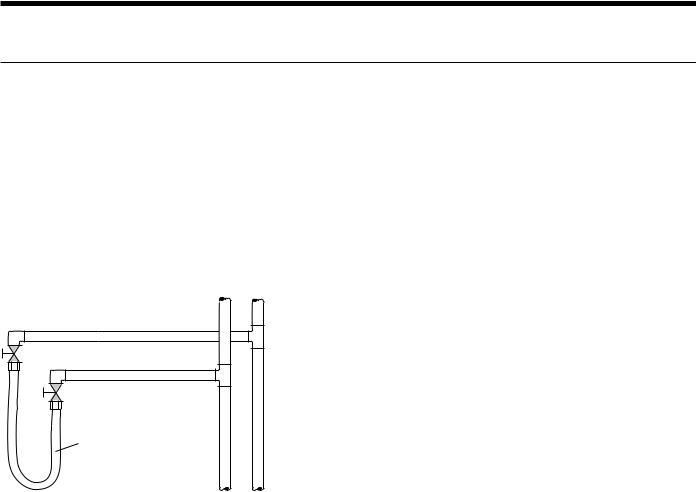
Flushing with Water Shutoff Valve Equipped Systems
Return Runout
Supply Runout
Mains 
Rubber Hose
Runouts Initially
Connected Together
The contractor should start the main circulator with the pressure reducing valve makeup open. Vents should be checked in sequence to bleed off any trapped air and to verify circulation through all components of the system.
As water circulates through the system, the contractor should check and repair any leaks found in the piping system. Drain(s) at the lowest point(s) in the system should be opened for initial flush and blowdown, making sure water fill valves are set at the same rate. Check the pressure gauge at the pump suction and manually adjust the makeup water valve to hold the same positive pressure both before and after opening the drain valves. Flushing should continue for at least two hours, or longer if required, until drain water is clean and clear.
The supplemental heater and/or circulator pump, if used, should be shut off. All drains and vents should be opened to completely drain the system. Short-circuited supply and return runouts should now be connected to the unit supply and return connections.
Refill the system with clean water. Test the system water for acidity and treat as required to leave the water slightly alkaline (pH 7.5 to 8.5). The specified percentage of antifreeze may also be added at this time. Use commercial grade antifreeze designed for HVAC systems only. Environol™ brand antifreeze is recommended.
Once the system has been filled with clean water and antifreeze (if used), precautions should be taken to protect the system from dirty water conditions. Dirty water will result in system-wide degradation of performance, and solids may clog valves, strainers, flow regulators, etc. Additionally, the heat exchanger may become clogged which reduces compressor service life and can cause premature unit failure.
In boiler/tower application, set the loop control panel set points to desired temperatures. Supply power to all
motors and start the circulating pumps. After full flow has been established through all components including the heat rejector (regardless of season), air vented and loop temperatures stabilized, each of the units will be ready for check, test and start up and for air and water balancing.
Ground Source Loop System Checkout
Once piping is completed between the unit pumping system and ground loop, final purging and charging of the loop is needed. A high pressure pump is needed to achieve adequate flow velocity in the loop to purge air and dirt particles from the loop itself. Antifreeze solution is used in most areas to prevent freezing. Flush the system adequately to remove as much air as possible; then pressurize the loop to a static pressure of 40-50 PSI (summer) or 50-75 PSI (winter). This is normally
adequate for good system operation. Loop static pressure may decrease soon after initial installation, due to pipe expansion and loop temperature change. Running the unit for at least 30 minutes after the system has been completely purged of air will allow for the “break-in” period. It may be necessary to adjust static loop pressure (by adding water) after the unit has run for the first time. Loop static pressure will also fluctuate with the seasons. Pressures will be higher in the winter months than during
the cooling season. This fluctuation is normal and should be considered when charging the system initially.
14
Loading...