

WaterFurnace OM2005A Owner's Manual
Owner’s Manual

INTRODUCTION
Congratulations on your WaterFurnace purchase!
Thank you for purchasing a WaterFurnace geothermal heating and cooling system. You have joined hundreds of
thousands of smart homeowners all over the world who have discovered that geothermal systems are the ultimate heating and cooling technology, providing the best combination of comfort, efficiency, reliability, and safe,
clean, quiet operation. That’s why our systems are recognized as being “Smarter From The Ground Up”. We’re
confident that your investment in the system will bring you many years of exceptional performance, comfort and
savings.
For a quick reference, write your WaterFurnace Dealer's name, telephone number and other important
information below:
Company Name:
Telephone Number: Emergency:
Date of Installation: Warranty:
Unit Model Number: Serial Number:
Type of Loop System (see page 12).
Check one:
Horizontal Closed Loop (Type , # Trenches/Bores , Trench Length , Depth )
Vertical Closed Loop (# Boreholes , Depth of Boreholes )
Pond Loop (# Coils , Ft. of Pipe , Pond Depth )
Open Loop / Well Water (Gallons per minute , Discharged to )
Loop Antifreeze (Type: )
MAJOR OPTIONS INSTALLED (CHECK ALL THAT APPLY):
Auxiliary Heat (Internal , External , kW )
Hot Water Assist:
Electronic Air Cleaner (Brand: )
Electrostatic Air Filter (Brand: )
Zone Control (Brand: , # zones )
Humidifier (Brand: )
Other:
2

Warranty Registration Warranty Registration
In order to receive full warranty benefits,
it is necessary to register your unit.
There are two easy ways to register--
1. Register on-line at: www.wfionline.info
or
2. Complete the Warranty Registration
Card to the right, tear out and mail.
Note: We respect your privacy. Please be
assured that we will not provide your personal
information to any outside company.
For your records --
I registered my warranty:
□ Online (date _______________ )
□ By mail (date _______________ )
Thank you!
What warranty do I have?
Overall term of warranty: _____ Years
Term of Parts warranty: _____ Years
Term of Compressor warranty: _____ Years
Term of Labor Allowance on
warranted parts: _____ Years
Term of Labor Allowance on
compressor : _____ Years
Term of Workmanship and
dealer supplied materials: _____ Months
Warranty for Accessories:
Item Years
Owner’s Name:
E-mail:
Address:
City:
State/Province:
Country:
Zip Code/Postal Code:
Day Phone:
Date of Installation:
Dealer Name:
Model Number:
Serial Number:
Loop Type: □ Open Loop/Well □ Closed Loop
Installation: □ New Construction □ Replacement
We request the following information to help us achieve
better communication to existing and potential customers.
Your response is confidential.
Size of Home: □ Under 1500 square ft.
Location of Home: □ Rural □ Suburban □ Urban
Value of Home:
□ 1500 to 2499 square ft.
□ 2500 to 4000 square ft.
□ Over 4000 square ft.
□ Under $100,000
□ $100,000 to $200,000 □ $200,001 to $500,000
□ Over $500,000
How did you hear about our products?
(Check all that apply.)
□ Print Advertisement □ Website
□ Radio Commercial □ TV Commercial □ Billboard
□ Open House or Field Day □ Home Show
□ Builder □ Utility Company □ Friend or Relative
□ Heating/Cooling Contractor □ Other: __________
_______________________ _____
_______________________ _____
_______________________ _____
_______________________ _____
_______________________ _____
What are the three most important reasons you
decided to purchase a system?
□ Energy savings □ Comfort
□ Reliability/Low Maintenance □ Safety
□ Quiet □ Long Equipment Life □ Innovation
□ Rebate/Incentive □ Recommendation of Others
□ Environmentally Friendly □ Other: ____________

FORT WAYNE IN 46809-9794
9000 CONSERVATION WAY
ATTN: WARRANTY REGISTRATION DEPT
WATERFURNACE INTERNATIONAL
Stamp
Here
Place

TABLE OF CONTENTS
Table of Contents
WARRANTY REGISTRATION & RECORD ...........................(tear out card)
GEOTHERMAL SYSTEM TECHNOLOGY & BENEFITS ...........................4
ABOUT YOUR WATERFURNACE SYSTEM .........................................5-17
How Geothermal Systems Work .........................................................6-9
Typical Installation & Components ..................................................10-11
Closed Loop Systems ..........................................................................12
Your Loop Location ..............................................................................
Open Loop Systems ............................................................................14
Safety Warnings ...................................................................................
Warranty Explanation ...........................................................................
Warranty Certificate .............................................................................
THERMOSTAT OPERATION ................................................................
General Thermostat Information ..........................................................18
Thermostat Identification ......................................................................
TA32U02 Thermostat Operation .....................................................
TP32H03 Thermostat Operation .....................................................
TA32H01 Thermostat Operation ..........................................................
TM21H02 Thermostat Operation .........................................................
HOMEOWNER MAINTENANCE ..........................................................26-27
TROUBLESHOOTING ...............................................................................28
13
15
16
17
18-28
19
20-21
22-23
24
25
FAQs, GENERAL INFORMATION & OPERATING TIPS .....................29-36
ENERGY SAVING TIPS .............................................................................37
PRODUCT INFORMATION FOR UNITS & ACCESSORIES ................38-54
Model Number & Serial Number Reference ........................................39
E Series Unit Information .....................................................................40
ES Series Unit Information ...................................................................41
EW Series Unit Information ..................................................................42
Premier Unit Information ......................................................................43
Premier Split Unit Information ..............................................................44
Synergy3 Unit Information ...................................................................45
Versatec Unit Information .....................................................................
Optional Hot Water Assist ....................................................................
Auxiliary Heater ................................................................................... 48
Humidifier ............................................................................................ 49
Electronic Air Cleaner ......................................................................... 50
Electrostatic Air Filter .......................................................................... 51
Flow Center ..........................................................................................52
IntelliZone ............................................................................................53
Other Accessories ............................................................................... 54
WATERFURNACE PROMOTIONAL MERCHANDISE .............................
46
47
55
GLOSSARY................................................................................................56
PREVENTIVE MAINTENANCE SERVICE RECORD ................................57
3
GEOTHERMAL SYSTEM TECHNOLOGY & BENEFITS
GEOTHERMAL SYSTEM TECHNOLOGY & BENEFITS
Geothermal heating and cooling technology is ideal because it provides exceptional performance while
ronmentally-friendly. Your investment in a WaterFurnace system will provide you with many years of benefits including:
being envi-
Energy Savings
WaterFurnace units deliver 3 to 4 units of energy for every 1 unit of energy consumed. Many homeowners experience
energy savings from 30% to 60% over other ordinary heating and cooling systems.
Cost Effective
Because of the extraordinary efficiency of a WaterFurnace system, any added investment related to installing a geothermal unit is usually more than offset by your energy savings.
Comfort
You’ll experience consistent, precise temperature control without the hot
blasts of air associated with gas furnaces or the cold blow of an air source
heat pump.
Reliable
The WaterFurnace reputation for reliability has been earned by using only the
highest quality components, design, and workmanship. Like your refrigerator,
your geothermal unit will provide many years of worry free operation.
Quiet
Unlike ordinary air conditioners or heat pumps, there is no noisy outdoor unit.
Our units are designed and constructed for “whisper quiet” operation, similar
to your refrigerator.
Safe & Clean
WaterFurnace units don’t burn fossil fuels, so there’s no flame, fumes, combustion or concerns about carbon monoxide poisoning.
Environmentally Friendly
Your geothermal system doesn’t release harmful greenhouse gasses into the air, unlike a fossil fuel burning furnace.
The reduced energy consumption of a geothermal system further reduces the need for more coal-fired or nuclear power
generating plants and places less demand on our current capability to produce electricity. Geothermal units use far less
refrigerant than ordinary heat pumps or air conditioners, and are factory sealed to prevent leakage.
We’re confident that your investment in a WaterFurnace system will provide you with many years of savings, comfort, and safe, clean, reliable, quiet operation.
4

ABOUT YOUR WATERFURNACE SYSTEM
ABOUT YOUR WATERFURNACE SYSTEM
This section includes some detailed information about how geothermal technology works, and how the different components used in the system work together to provide you with the finest comfort system available. You'll find useful information about the refrigeration process, loop systems, safety, and warranties.
Although the mechanics behind this technology may seem complicated, it's based on the same technology that's used
for your refrigerator—it's simply a device that moves heat energy from one place to another. And because of the infinite
heat storage ability of the earth, you have a free, unlimited supply of energy in your own yard. In fact, for every one unit of
electricity the system consumes, four units of energy are provided free from the earth and delivered into your home. This
energy flow can be easily represented by the diagram below.
1 unit of electricity
4 units of "free"
energy from the
cooling delivered into
your home
earth
Interesting Facts
• According to the Environmental Protection Agency (EPA), GeoExchange technology is the most
energy-efficient, environmentally-clean and cost-effective space conditioning system available.
• The EPA found that the systems can reduce energy consumption and corresponding emissions
by over 40% compared to air source heat pumps and by over 70% compared to electric resistance
heating with standard air conditioning equipment.
• If one in twelve California homes installed a GeoExchange system, the energy savings would
equal nine new power plants.
• Installing a GeoExchange system in a typical home is equal, in greenhouse gas reduction, to
planting an acre of trees, or taking two cars off the road.
• Current GeoExchange installations equal 14 million barrels of crude oil saved per year.
• The ground absorbs 47% of the sun’s energy that reaches the earth. This amount of energy
represents 500 times more than mankind needs every year.
5 units of heating or
5

ABOUT YOUR WATERFURNACE SYSTEM
HOW GEOTHERMAL SYSTEMS WORK
The Interesting Basics…
Geothermal heat pumps utilize some of the same technology found
in your home's refrigerator. They are both devices that move heat
energy. Your refrigerator removes heat from the food and transfers
it to the air in your home. Your geothermal heat pump removes
heat energy from the earth to heat your home and removes heat
energy from inside your home to cool it.
A Ground Source Heat Pump System consists of a water-to-air or
water-to-water heat pump, connected to a series of long plastic
pipe buried below the earth’s surface, or placed in a pond. These
systems can also utilize well water instead of the earth loop. As
fluid from the earth loop or well water is moved through the unit, the
heat pump transfers thermal energy that heats or cools the home
or building.
The ground serves as a giant solar collector, storing heat energy. At depths greater than 30 feet deep, the tem
perature is about the same as the average annual outdoor air temperature for that climate. Air temperatures may
fluctuate as much as 50° F above and below the average annual temperature. However, only a few feet below the
surface, the changes in earth temperatures are much less severe. Earth temperature variations decrease with increasing depth. During heating, the earth serves as a heat source. During cooling, the earth serves as a heat sink.
The earth loop is placed in the ground either horizontally or vertically, or it can be placed in a pond. Water (or water
and anti-freeze) is circulated through the pipe, transporting heat to the heat pump during the heating mode and
away from the heat pump during the cooling mode. The heat transfer takes place inside the heat pump in a waterto-refrigerant heat exchanger.
-
The Boring Details…
HEAT PUMP OPERATION
Geothermal heat pump systems consist of four circuits:
1. Air circuit—The duct system that distributes the air throughout the home or building and returns it to the unit.
2. Refrigerant circuit—A sealed and pressurized circuit of refrigerant including compressor, expansion valve,
water-to-refrigerant heat exchanger, air coil, reversing valve. The refrigerant is either R-22 or R-410A.
3. Ground loop circuit—The piping system buried in the ground or in the pond (or well water), with fluid that is
circulated by pumps to and from the geothermal unit.
4. Hot water circuit—Domestic water can be heated in a geothermal unit with a device called a desuperheater. A
piping connection is made from the geothermal unit to the water heater.
Each of these circuits is closed and sealed from the others—there is no direct mixing. However, heat energy does
mix from the refrigeration circuit to the other three circuits.
The air circuit, the earth loop circuit, and the domestic hot water circuit always travel in the same direction. However, the refrigeration circuit will change direction depending on what mode (heating or cooling) the unit is in. (The
exception to the change in direction of refrigerant flow is the flow through the compressor. This change of direction
is controlled by the reversing valve.)
6
(
(
(
(
(
(
(
(
(
(
(
(
(
(
(
(
(
(
(
(
(
(
(
(
(
(
(
(
(
(
Hot
Water to
House
Supply
Air
Duct
Cold
Water
to Unit
Water
Heater
Water to Loop
Pump
Hot
Water
from Unit
Water
from
Loop
Earth Loop-
Horizontal, Vertical,
Pond (or Well Water)
Air
Coil
Blower
Return
Air
Duct
Cold
Warm
Hot
Cold
Warm
ABOUT YOUR WATERFURNACE SYSTEM
Heating Mode
During heating, a geothermal system absorbs the heat from the ground via the earth loop. The heating cycle starts
as cold, liquid refrigerant passes through the water-to-refrigerant heat exchanger (coax, and also the evaporator
during heating). The coax is made of copper (or copper and nickel) and consists of a tube within a tube—water from
the loop travels through one tube (the inside tube), refrigerant passes through the other (outer) tube.
As the loop fluid flows through the coax, the heat energy transfers from the loop fluid to the refrigerant through the
copper wall separating the two. This heat transfer causes the cold liquid refrigerant to turn into a gas. (Unlike water,
refrigerant changes from a liquid into a gas at a very low temperature.) The now gaseous refrigerant is sucked into
the compressor where it is compressed. After compression, the refrigerant will be very hot (approximately 165
and discharged through the reversing valve and into the air coil.
The air coil is a radiator-like device that has thin aluminum “fins” attached to the copper refrigerant tubing. The
refrigerant passes through the air coil (the condenser during heating). As air from the return air duct system passes
over the air coil, heat is released from the refrigerant and absorbed by the cooler air. The result is warm air (typically
95° to 105° F) which is delivered through the duct system by the blower.
The refrigerant, now cooled again, passes through the expansion valve (which acts as a flow control), returning to
the coax where it can accept more heat from the warmer loop fluid.
This process is continuous during the heating mode.
° F)
Heating Operation
7

(
(
(
(
(
(
(
(
(
(
(
(
(
(
(
(
(
(
(
(
(
(
(
(
(
(
(
(
(
(
Hot
Water to
House
Supply
Air
Duct
Cold
Water
to Unit
Water
Heater
Water to Loop
Pump
Hot
Water
from Unit
Water
from
Loop
Earth Loop-
Horizontal, Vertical,
Pond (or Well Water)
Air
Coil
Blower
Return
Air
Duct
Warm
Cool
Cold
Cool
Warm
ABOUT YOUR WATERFURNACE SYSTEM
Cooling Mode
During cooling, a geothermal system rejects the heat from the indoor air into the earth loop. The cooling cycle starts
as cold, liquid refrigerant passes through the air coil (the evaporator during cooling).
As the refrigerant flows through the air coil, the heat energy transfers from the warm return air to the refrigerant.
This heat transfer causes the cold liquid refrigerant to turn into a gas. The compressor draws the refrigerant gas,
compresses it, and discharges it through the reversing valve. During cooling, the reversing valve is energized, which
changes the openings from one port to another, causing the refrigerant flow to go in the opposite direction that it
was in the heating mode. (However, the flow to the compressor does not change direction.)
After compression, the hot refrigerant passes through the coax (the condenser during cooling). In the coax, the hot
refrigerant releases its heat energy to the cool loop fluid through the copper walls. Now cooled and liquified, the
refrigerant passes through the expansion valve, back to the air coil. Warm air passing over the cool air coil causes
the air to be cooled and dehumidified.
This process is continuous during the cooling mode.
Cooling Operation
8
Drain Valve
In
P/T Relief
Valve
Cold
Water In
Hot
Water Out
DHW
Water In
DHW
Wa ter Out
ABOUT YOUR WATERFURNACE SYSTEM
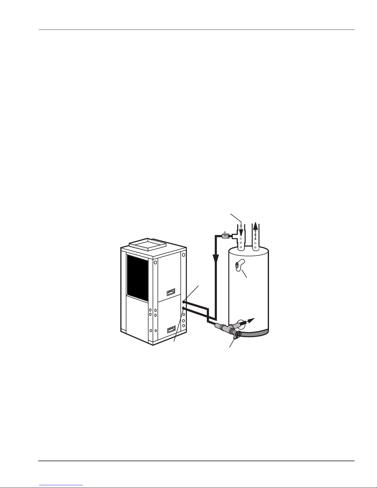
Hot Water Assist
Many geothermal units installed in homes have an optional feature called a hot water generator. This component removes excess heat from the refrigerant circuit and adds it to a hot water circuit in the unit. For more information refer to
page 47.
It is important to note that the Hot Water Assist function simply assists in preheating water. The temperature rise
through the unit is generally 5 -10º F.
The amount of hot water generated is a function of the model and run time of the unit. On very hot days and cold
days, the hot water generator could produce more hot water required for the home due to the long run times of the
unit. On milder days when the unit has short duty cycles, the electric elements in the water heater will maintain the
desired temperature so there will always be enough hot water for the homeowner.
Some installations use a single tank for storage of hot water. Other installations use two tanks to provide extra hot
water capacity with added efficiency.
Typical Desuperheater Installation
9
Flexible
Duct Collar
Vibration
Absorbing Pad
Drain
Desuperheater
Connections
Auxiliary
Heater
Knockout
Low Voltage
to Thermostat
and Valve
Unit Supply
Aux. Heat Supply
Disconnects
(IfApplicable)
Compressor
Line Voltage
Drain Valve
In
Cold
Water In
Hot
Water Out
DHW
Water Out
TO
LOOP
G
e
o
L
i
n
k
®
F
l
o
w
C
e
n
t
e
r
P/T Plugs
Filter Access
Status Lights
ABOUT YOUR WATERFURNACE SYSTEM
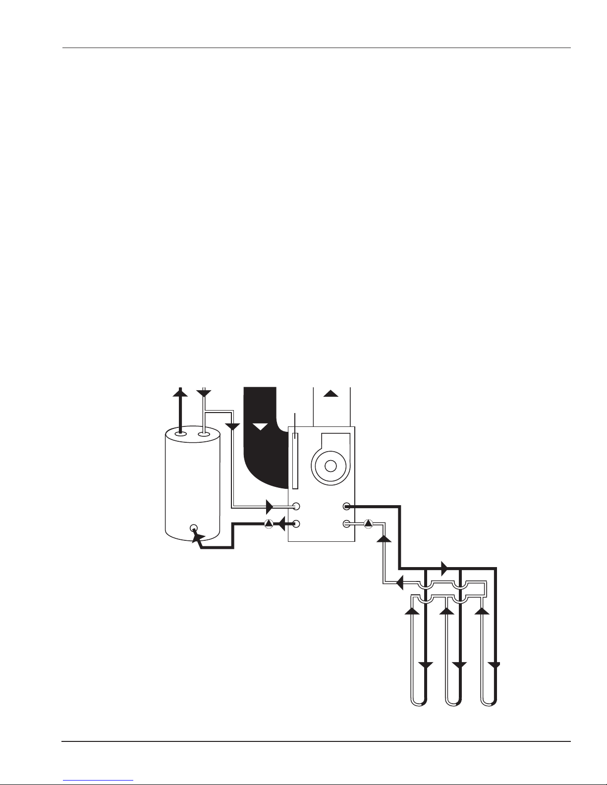
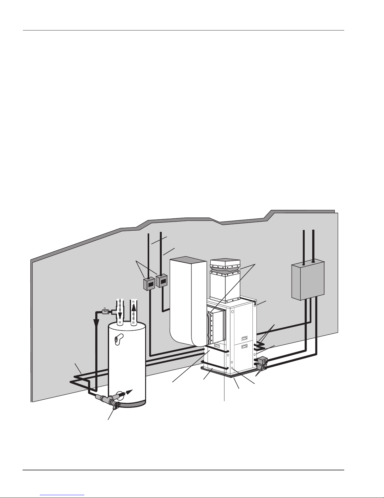
TYPICAL INSTALLATION AND COMPONENTS
Your geothermal system is actually a collection of components working together to perform the heating, cooling and
water heating functions. The basic system includes the unit, power supply, a control component, the water circuit
and a distribution method. Many additional optional accessories are available, but listed below are the basic components used in most every installation.
Closed Loop Components
Major components in a closed loop earth coupled system include:
• Geothermal unit placed on mounting pad
• Thermostat
• Earth loop piping
• Earth loop circulators (pumps)
• Electrical supply
• Duct system (except for radiant floor heating systems)
• Hot water piping (if hot water generator used)
• Auxiliary heater (if used)
Typical Closed Loop System
10
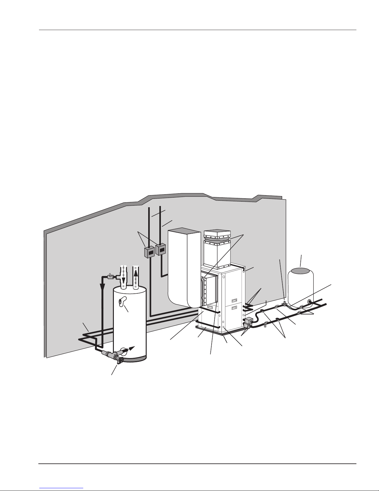
Open Loop Components
Electrical
Flexible
Duct Collar
Vibration
Absorbing Pad
P/T Plugs
Condensate
Drain
Desuperheater
Connections
Auxiliary
Heater
Knockout
Low Voltage
to Thermostat
and Valve
Unit Supply
Aux. Heat Supply
Water Out
Water In
Shut Off Valves
Boiler Drains
For Flushing
Disconnects
(IfApplicable)
Rubber Bladder
Expansion Tank
Solenoid
Valve
Shut Off Valves
Flow Control
Valve
Power
Supply
Drain Valve
In
P/T Relief
Valve
Cold
Water In
Hot
Water Out
DHW
Water Out
Status Lights
Filter Access
Major components in an open loop/well system include:
• Geothermal unit placed on mounting pad
• Thermostat
• Well & pump
• Pressure tank
• Supply water piping
• Discharge water piping with solenoid valves and flow regulators
• Shut-off/isolation valves and drain valves
• Electrical supply
• Duct system (except for radiant floor heating systems)
• Hot water piping (if hot water generator used)
• Auxiliary heater (if used)
Typical Open Loop System
ABOUT YOUR WATERFURNACE SYSTEM
11
ABOUT YOUR WATERFURNACE SYSTEM
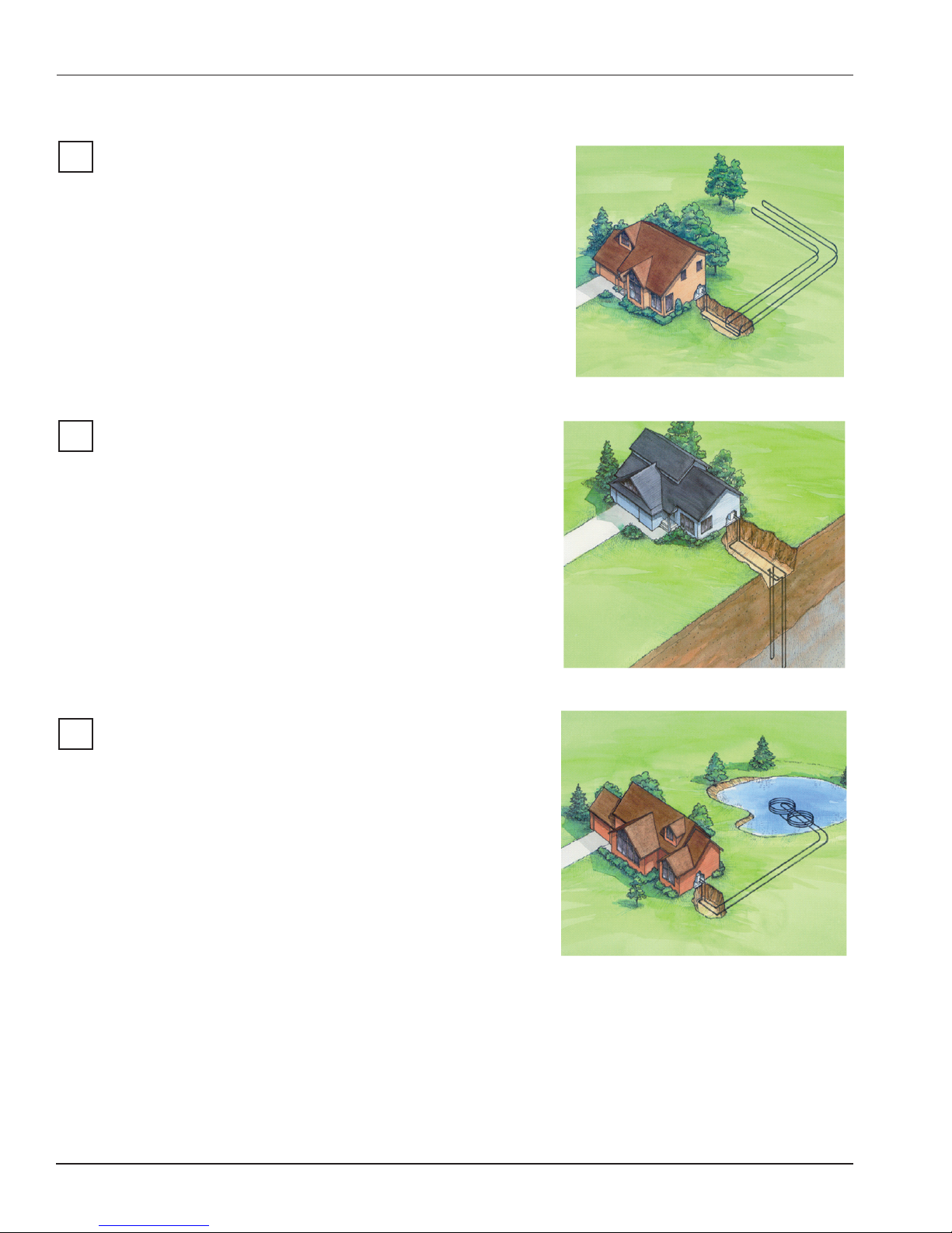
Closed Loop Systems
Horizontal Loops
Horizontal earth loops are used where the space allowed for
the loop is not extremely limited. There are various designs of
horizontal loops. There is not one type of horizontal loop that
is best for every application. The selection of which type to use
should be based on system size, space available, soil conditions and the type of excavating equipment used. Regardless
of the type selected, operating costs will not vary substantially.
If you have this loop type, record information here:
Number of trenches or horizontal bores: _____
Length of each trench: _____
Number of pipes in trench: _____ Pipe size: _____
Vertical Loops
Vertical loops are used where space is limited or where soil conditions are not conducive to horizontal loops. Installing vertical
loops requires the use of a drilling rig. Multiple holes are bored.
A double pipe connected with a U-bend is inserted into each
hole. The hole is the filled with grout to provide good contact
around the pipe and to seal the hole. The vertical pipes are then
connected to a header system horizontally a few feet below the
surface.
If you have this loop type, record information here:
Number of bore holes: _____
Depth of each bore hole: _____ Pipe size: _____
Pond Loops
Pond loops are a cost effective way to install a geothermal system, because trenching is limited to only the supply and return
piping from the pond to the house.
Pond loops consist of a series of coils connected together, and
placed at the bottom of the pond. In order for a pond to be suitable for a geothermal application for a typical home, the pond
should be at least ½ acre in surface area and at least 8 ft. deep,
even during a dry spell. Ideally, the pond should be close to the
home (less than 200 ft.). If the pond is farther from the home,
the benefit of using a pond loop is reduced due to added trenching, materials and pumping costs.
If you have this loop type, record information here:
Number of coils: _____ Pipe size: _____
Depth of pond where coils are located: _____
Water Supply for all Closed Loops
Closed loops require no regular maintenance. However, if you notice air noise within the piping or if your loop is
ever damaged by excavation, contact your dealer.
12
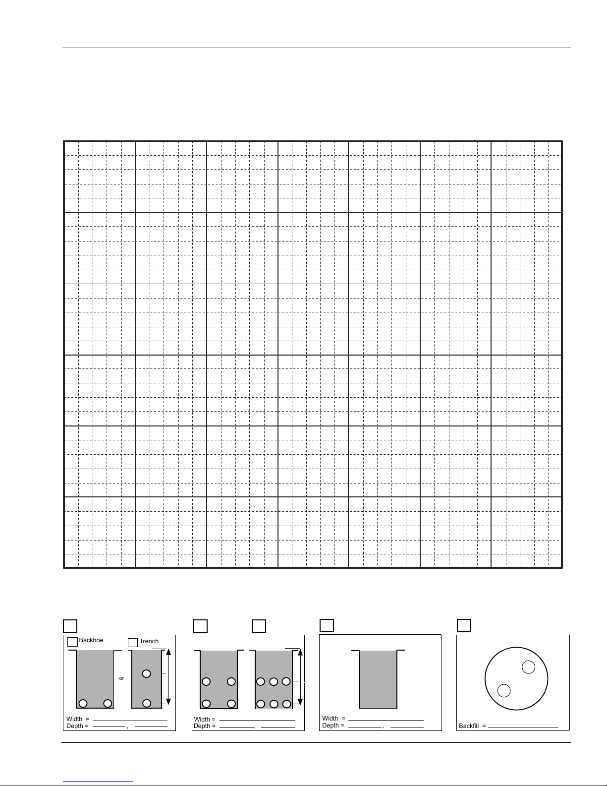
Backhoe
Trench
Width =
Depth = ,
or
Width =
Depth = ,
Backfill =
Width =
Depth = ,
ABOUT YOUR WATERFURNACE SYSTEM
Your Loop Location
It is strongly recommended that you have a record of the location of your earth loop. Using the grid below, draw a
bird’s eye view of the property where the loop is located. Include the house and measurements from various points
so that there is no question about the location of the piping system. You may also want to include the location of any
underground utilities.
Scale: 1 square equals ___ ft.
2 Pipe 4 Pipe
6 Pipe
Other
1 Pair Vertical
13

ABOUT YOUR WATERFURNACE SYSTEM
Open Loop Systems
Open Loop or Well Water Systems
An alternative to closed loops are open loop systems, also known as
well-water systems. If your system is an open loop, it uses water that
comes into your home from your well. Water from the well is circulated
through the unit whenever the unit is heating or cooling. When the unit
is not running, it is not using any water.
Once the water has run through the unit, it is discharged into a location
like a pond, drainage ditch, field tile, etc. Water used in the unit is not
re-used for other domestic purposes.
If you have an open loop, record information here:
Total Domestic System designed for _____ gpm.
Geothermal System designed for ______ gpm.
Well depth: _______ ft. Pump depth: ______ ft.
Water table depth: ______ ft. Pump HP: ______
Well yield: ______ gpm
Unit Maintenance with Open Loop Systems
Depending on the water quality, some maintenance is usually required with a well water system. Because of minerals and other particles in the water, without a routine of preventive maintenance, this material may eventually begin
to clog the heat exchanger in the unit. When this happens, the efficiency and capacity of the unit is decreased,
eventually to the point where failure may occur.
To minimize the potential of this happening, a heat exchanger cleaning schedule should be established with your
dealer. The frequency will depend on the specific quality of your well water. Some homeowners find that they can
go a few years between cleanings; others may need to have the heat exchanger cleaned yearly. In order to achieve
optimum performance, energy savings and long system life, it is necessary to have your dealer perform this service
as needed. Remember-- preventive maintenance is less expensive than replacing major components.
The cleaning procedure requires special equipment and chemicals. Therefore, do not attempt to clean the heat
exchanger yourself.
Water Supply
An adequate water supply to the unit is very important. Do not let anyone disrupt the water supply by rerouting the
supply line or tapping into it without first checking with your dealer. If the well pumping system requires service or is
inoperable, your unit should be turned off or placed into emergency heat until an adequate water supply is restored.
14
ABOUT YOUR WATERFURNACE SYSTEM
Safety Warnings
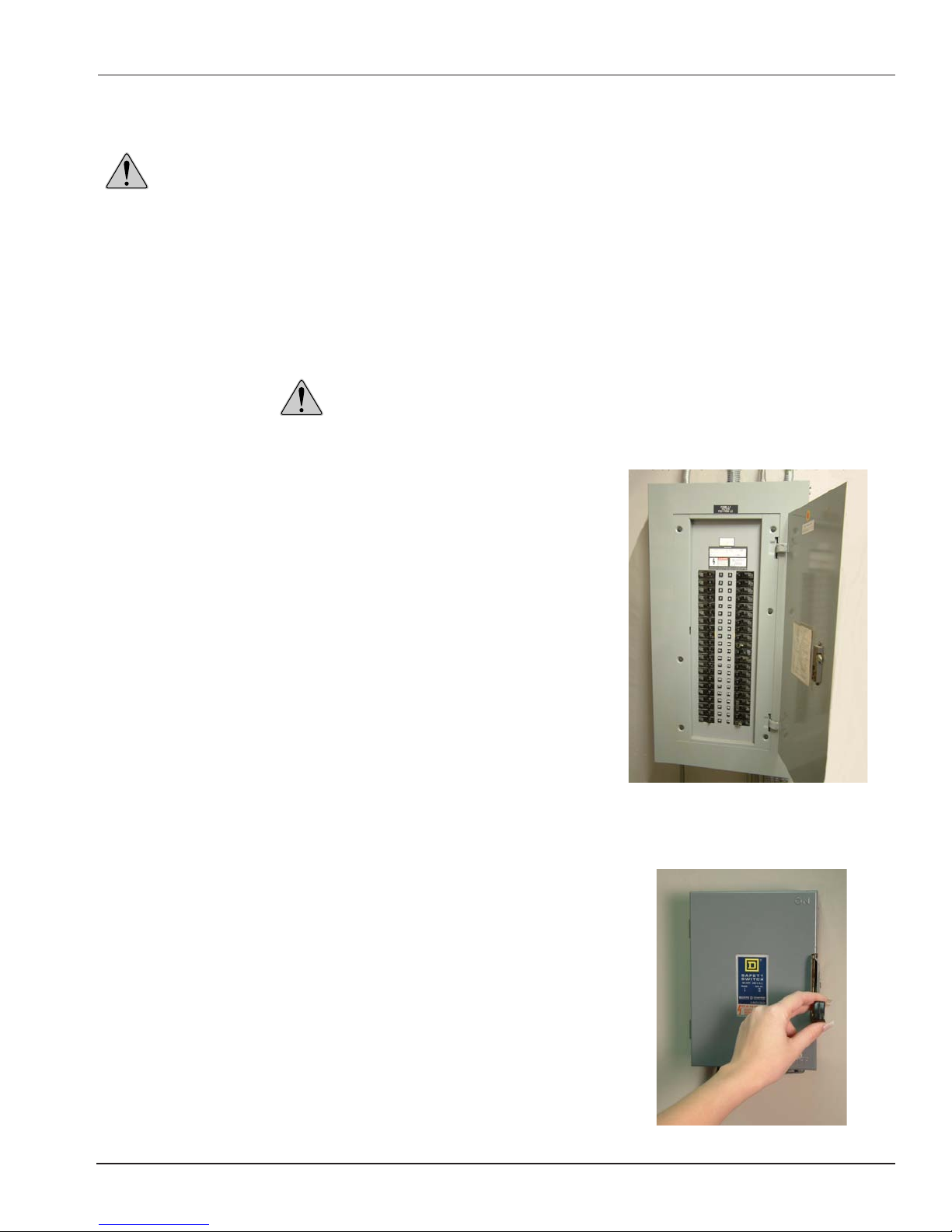
WARNING: Equipment used for heating, air conditioning and water heating can cause injury if
safety precautions are not observed. These systems generally use a 230 volt power supply which is
double the voltage used by other household appliances. Electrical shock from these systems could
cause personal injury or death. Before performing any service or maintenance operations on a system, turn off main power switches to the unit, and turn off the auxiliary heater power also if used.
Although your geothermal unit has been designed and manufactured with your safety in mind, and is certified to the
safety standards of ETL, failure to observe safety precautions can result in injury. Only trained and qualified service
personnel should install, repair, service or adjust heating and air conditioning equipment. Untrained personnel can
perform the basic maintenance functions listed below. All other operations should be performed by trained service
personnel. When working on heating and air conditioning equipment, observe precautions in the literature, tags and
labels attached to the unit and any other safety precautions that may apply.
Do not allow children or pets to play around the unit.
Safety Precautions
When performing the following functions, adhere to these safety precautions:
•
Replacing a disposable filter — Turn off the unit and fan at the
thermostat.
Cleaning an electrostatic filter — Turn off the unit and fan at the
•
thermostat
Cleaning an electronic air cleaner — Turn off all power supplies
•
to the unit and the air cleaner. Wait 5 minutes to allow static to
discharge.
Checking or cleaning the internal condensate drain pan — Turn off
•
all power supplies to the unit, and be careful around the sharp fin
edges of the air coil. Wear safety glasses and work gloves. Do not
allow water to drip onto electrical components in the unit.
Cleaning or replacing media for unit-mounted or duct-mounted
•
humidifiers — Turn off all power supplies to the unit and humidifier.
Cleaning thermostats — Do not spray cleaning solution directly
•
onto the thermostat. Wipe down with a damp cloth.
Cleaning units — Turn off all power supplies to the unit. Do not
•
spray water or cleaning solutions directly onto the unit. Wipe down
with a damp cloth.
Safety Tips
We want you and your family to be safe in your home. Here are some
additional useful safety tips:
•
Have working smoke detectors (replace batteries two times each year).
Have working carbon monoxide detectors (even in all-electric homes).
•
Have fire extinguishers available in kitchen, utility room, garage, etc.
•
Have a well-stocked first aid kit available.
•
Have an emergency/evacuation plan in place for all members of the
•
family.
Breaker Box
Disconnect Box
15

ABOUT YOUR WATERFURNACE SYSTEM
Warranty Explanation and Coverage
What about my warranty?
WaterFurnace offers the best warranty in the industry!
Our standard warranty provides coverage for all unit parts for a period of 10 years. In addition to replacement parts
coverage, your servicing dealer receives a repair or replacement labor allowance on warranted components in the
unit. However, WaterFurnace also offers several other warranty options, depending on the needs of the customer.
Your independent WaterFurnace dealer should have previously discussed with you the terms of these options, and
together, you have selected the one that best fits your needs. Not all customers select the 10-year coverage, so if
you are unsure as to your warranty period, contact your WaterFurnace dealer.
What items are covered under the warranty?
Our standard warranty covers parts and most accessories. “Parts” are considered to be any factory-installed
component inside the unit including, but not limited to the compressor, reversing valve, expansion valve, electrical
components, air coil, heat exchanger, etc. Upon failure of a part, the company provides a replacement part to the
servicing contractor at no charge. “Accessories” are generally external to the unit and include items like thermostats,
pumps, humidifiers, etc. In most cases, accessories supplied by WaterFurnace carry the same warranty as the unit.
Some warranties do not cover accessories. Contact your dealer to determine the specific terms and extent of your
coverage.
Will I have to pay labor costs for warranty repairs?
Some warranty options include a Labor Allowance, which is an amount credited to your servicing company based
on the type of repair made. The Labor Allowance is designed to reduce the cost of repairs. However, it may not
cover the entire labor fee charged by your dealer. Not all warranty options include a labor allowance.
16
 Loading...