

WaterFurnace NSKW06, NSKW08, NSKW12, NSKW17 Installation Information
NSKW
Geothermal Hydronic Heat Pump
Installation Information
Water Piping Connections
Electrical Data
Startup Procedures
Preventive Maintenance
Versatec Ultra NSKW Installation Manual
IM2566WN 07/16


Table of Contents
Model Nomenclature . . . . . . . . . . . . . . . . . . . . . . . . . . . . . . . . . . . . . . . . . . . . . . . . . . . . . . . . . . . . . . 4
General Installation Information . . . . . . . . . . . . . . . . . . . . . . . . . . . . . . . . . . . . . . . . . . . . . . . . . . . . 5
VERSATEC ULTRA NSKW INSTALLATION MANUAL
Water Quality
Field Connected Water Piping. . . . . . . . . . . . . . . . . . . . . . . . . . . . . . . . . . . . . . . . . . . . . . . . . . . . 7-9
Potable Water Systems . . . . . . . . . . . . . . . . . . . . . . . . . . . . . . . . . . . . . . . . . . . . . . . . . . . . . . . . . 10-11
Hydronic Section . . . . . . . . . . . . . . . . . . . . . . . . . . . . . . . . . . . . . . . . . . . . . . . . . . . . . . . . . . . . . . 12-13
Accessories and Options. . . . . . . . . . . . . . . . . . . . . . . . . . . . . . . . . . . . . . . . . . . . . . . . . . . . . . . . . . 14
Electrical Data . . . . . . . . . . . . . . . . . . . . . . . . . . . . . . . . . . . . . . . . . . . . . . . . . . . . . . . . . . . . . . . . .14-15
Wiring Schematics . . . . . . . . . . . . . . . . . . . . . . . . . . . . . . . . . . . . . . . . . . . . . . . . . . . . . . . . . . . . .16-19
External Control . . . . . . . . . . . . . . . . . . . . . . . . . . . . . . . . . . . . . . . . . . . . . . . . . . . . . . . . . . . . . . . . .20
Converting to a Dedicated Cooling Unit . . . . . . . . . . . . . . . . . . . . . . . . . . . . . . . . . . . . . . . . . . . . 21
Unit Startup . . . . . . . . . . . . . . . . . . . . . . . . . . . . . . . . . . . . . . . . . . . . . . . . . . . . . . . . . . . . . . . . . . . . . 21
The Aurora Base Control System . . . . . . . . . . . . . . . . . . . . . . . . . . . . . . . . . . . . . . . . . . . . . . .22-25
Reference Calculations . . . . . . . . . . . . . . . . . . . . . . . . . . . . . . . . . . . . . . . . . . . . . . . . . . . . . . . . . . . 26
Legend and Notes . . . . . . . . . . . . . . . . . . . . . . . . . . . . . . . . . . . . . . . . . . . . . . . . . . . . . . . . . . . . . . .26
Pressure Drop . . . . . . . . . . . . . . . . . . . . . . . . . . . . . . . . . . . . . . . . . . . . . . . . . . . . . . . . . . . . . . . . . . . 27
Operating Limits . . . . . . . . . . . . . . . . . . . . . . . . . . . . . . . . . . . . . . . . . . . . . . . . . . . . . . . . . . . . . . . . . 27
. . . . . . . . . . . . . . . . . . . . . . . . . . . . . . . . . . . . . . . . . . . . . . . . . . . . . . . . . . . . . . . . . . . . 6
Physical Data . . . . . . . . . . . . . . . . . . . . . . . . . . . . . . . . . . . . . . . . . . . . . . . . . . . . . . . . . . . . . . . . . . . . 28
Flow Rates . . . . . . . . . . . . . . . . . . . . . . . . . . . . . . . . . . . . . . . . . . . . . . . . . . . . . . . . . . . . . . . . . . . . . . 28
Thermistor Resistance . . . . . . . . . . . . . . . . . . . . . . . . . . . . . . . . . . . . . . . . . . . . . . . . . . . . . . . . . . . .28
Operating Parameters . . . . . . . . . . . . . . . . . . . . . . . . . . . . . . . . . . . . . . . . . . . . . . . . . . . . . . . . . . . .29
Antifreeze Correction . . . . . . . . . . . . . . . . . . . . . . . . . . . . . . . . . . . . . . . . . . . . . . . . . . . . . . . . . . . .30
Troubleshooting Guideline for Refrigerant Circuit . . . . . . . . . . . . . . . . . . . . . . . . . . . . . . . . . . . . 31
HR Data. . . . . . . . . . . . . . . . . . . . . . . . . . . . . . . . . . . . . . . . . . . . . . . . . . . . . . . . . . . . . . . . . . . . . . 32-32
HE Data. . . . . . . . . . . . . . . . . . . . . . . . . . . . . . . . . . . . . . . . . . . . . . . . . . . . . . . . . . . . . . . . . . . . . . 34-35
DHW HE Data . . . . . . . . . . . . . . . . . . . . . . . . . . . . . . . . . . . . . . . . . . . . . . . . . . . . . . . . . . . . . . . . . . . 36
Heating and Cooling Cycle Analysis. . . . . . . . . . . . . . . . . . . . . . . . . . . . . . . . . . . . . . . . . . . . . . . .37
Troubleshooting Form . . . . . . . . . . . . . . . . . . . . . . . . . . . . . . . . . . . . . . . . . . . . . . . . . . . . . . . . . . . .38
Troubleshooting . . . . . . . . . . . . . . . . . . . . . . . . . . . . . . . . . . . . . . . . . . . . . . . . . . . . . . . . . . . . . . . . .39
Preventive Maintenance . . . . . . . . . . . . . . . . . . . . . . . . . . . . . . . . . . . . . . . . . . . . . . . . . . . . . . . . . 40
Service Parts . . . . . . . . . . . . . . . . . . . . . . . . . . . . . . . . . . . . . . . . . . . . . . . . . . . . . . . . . . . . . . . . . . . . 41
Technical Documentation . . . . . . . . . . . . . . . . . . . . . . . . . . . . . . . . . . . . . . . . . . . . . . . . . . . . . .42-45
Revision Guide. . . . . . . . . . . . . . . . . . . . . . . . . . . . . . . . . . . . . . . . . . . . . . . . . . . . . . . . . . . . . . . . . . .47
VERSATEC ULTRA NSKW INSTALLATION MANUAL
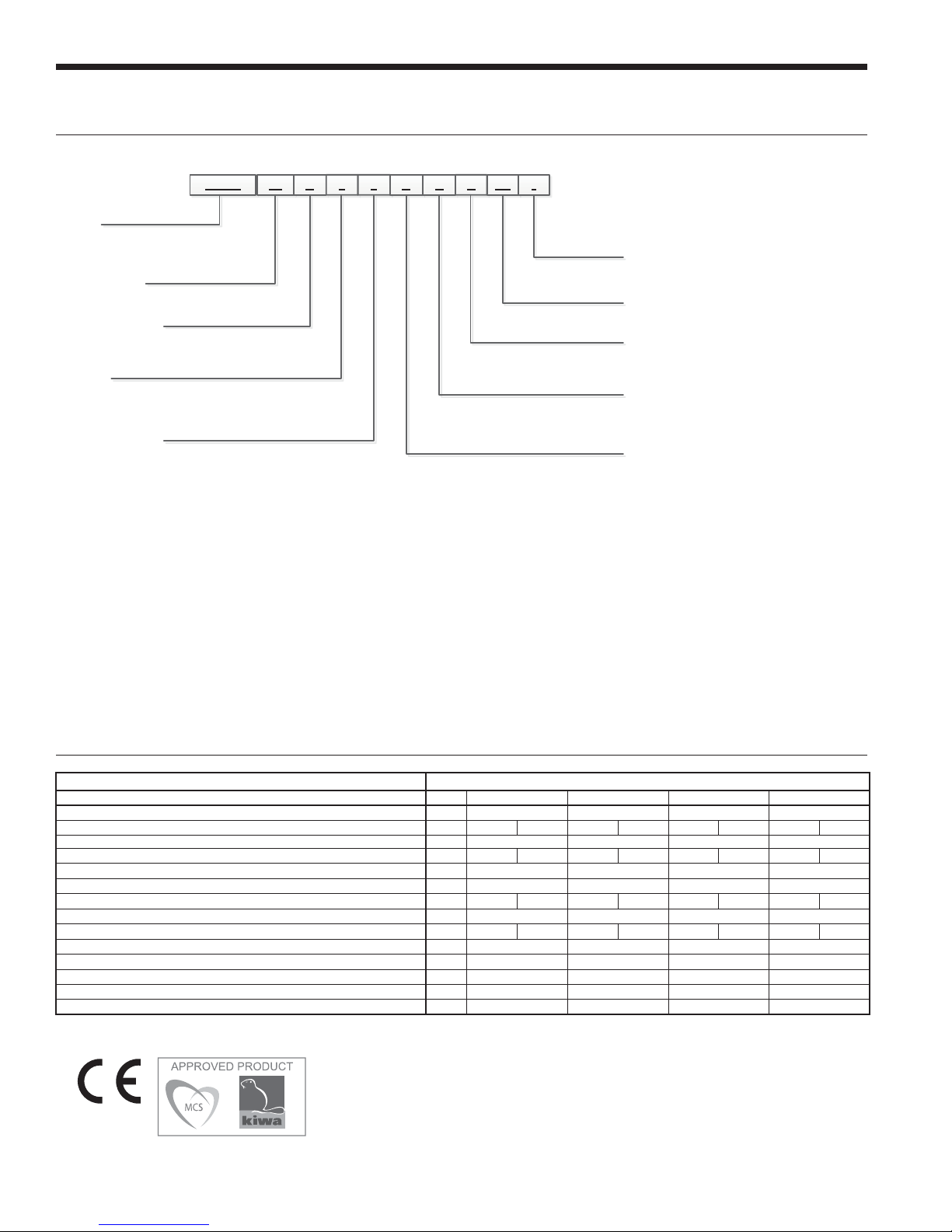
Model Nomenclature
1-4
NSKW 08 H 6 0 A C
Model
NSKW – Versatec Hydronic
Heat Pump
Unit Capacity
06, 08, 12, 17
Reversible Option
H- Heating Only
R- Reversible
Voltage
6 – 220-240/50/1
7 – 380-420/50/3
Hot Water Option
0 – No Hot Water Generation, No IntelliStart
2 – Hot Water Generation, No IntelliStart
3 – No Hot Water Generation, IntelliStart
5 – Hot Water Generation, IntelliStart
1
5-6 7 8 9 10 11
12
C
13-14
SS *
15
Vintage
* – Factory Use Only
Future Option
SS – Standard Option
Load Coax
C – Copper
N - Cupronickel
Source Coax
C – Copper
N – Cupronickel
Controls Option
A – Aurora™ Base Controls (ABC)
Rev.: 15 June 2016
2
NOTES: 1 – Available on 08, 12, 17 only. Hot water generator requires field installed external pump kit.
2 – NSKW06 heating only models are available only with copper double wall vented load coax for potable water,
and are not designed to be converted to dedicated cooling units.
Energy Labelling
Supplier WaterFurnace International, Inc.
Model NSKW06 NSKW08 NSKW12 NSKW17
Model hot water heater - - - Temperature application °C 35 55 35 55 35 55 35 55
Declared load profile for water heating - - - Seasonal space heating energy efficiency class, average climate A++ A++ A++ A++ A++ A++ A++ A++
Water heating energy efficiency class, average climate - - - Rated heat output (Pdesignh), average climate kW 6 8 12 17
Annual energy consumption space heating, average climate kWh 2,860 3,432 3,689 4,543 4,920 6,343 7,985 9,656
Annual energy consumption water heating, average climate kWh - - - Seasonal space heating energy efficiency, average climate % 160 119 178 132 187 137 164 126
Water heating energy efficiency, average climate % - - - Sound power level LWA indoors dB 57 57 61 63
Rated heat output (Pdesignh), cold climate kW 6 8 12 17
Rated heat output (Pdesignh), warm climate kW 6 8 12 17
Sound power level LWA outdoors dB dB - - - -
3/18/2016
All Versatec Ultra NSKW product is safety tested to CE standards and
performance tested in accordance with standard BS EN 14511-2.
4

General Installation Information
VERSATEC ULTRA NSKW INSTALLATION MANUAL
Safety Considerations
Installing and servicing air conditioning and heating
equipment can be hazardous due to system pressure and
electrical components. Only trained and qualified service
personnel should install, repair or service heating and air
conditioning equipment. When working on heating and
air conditioning equipment, observe precautions in the
literature, tags and labels attached to the unit and other
safety precautions that may apply.
Follow all safety codes. Wear safety glasses and work
gloves. Use quenching cloth for brazing operations. Have
fire extinguisher available for all brazing operations.
NOTE: Before installing, check voltage of unit(s) to ensure
proper voltage.
WARNING: Before performing service or
maintenance operations on the system, turn off
main power switches to the unit. Electrical shock
could cause serious personal injury.
Process Water Applications
For process water applications, it is recommended that
a secondary load heat exchanger be installed to prevent
corrosion to the unit’s primary coaxial coil. In situations
where scaling could be heavy or where biological growth
such as iron bacteria will be present, a closed loop system is
recommended. Over a period of time, ground water unit heat
exchanger coils may lose heat exchange capability due to a
buildup of mineral deposits. These can be cleaned only by
a qualified service mechanic as special pumping equipment
and solutions are required. Never use flexible hoses with a
smaller inside diameter than that of water connections.
WARNING: To avoid equipment damage, do not
leave the system filled in a building without heat
during cold weather, unless adequate freeze
protection levels of antifreeze are used. Heat
exchangers do not fully drain and will freeze
unless protected, causing permanent damage.
Unit Location
Provide sufficient room to make water and electrical
connections. If the unit is located in a confined space,
provisions must be made for unit servicing. Locate the
unit in an indoor area that allows easy removal of the
access panels and has enough space for service personnel
to perform maintenance or repair. These units are not
approved for outdoor installation and, therefore, must be
installed inside the structure being conditioned. Do not
locate units in areas subject to freezing conditions.
WARNING: Do not store or install units in
corrosive environments or in locations subject
to temperature or humidity extremes (e.g. attics,
garages, rooftops, etc.). Corrosive conditions and
high temperature or humidity can significantly
reduce performance, reliability, and service life.
Mounting Units
Prior to setting the unit in place, remove and discard the
compressor hold down shipping bolt located at the front of
the compressor mounting bracket.
Units should be mounted level on a vibration absorbing pad
slightly larger than the base to provide isolation between
the unit and the floor. It is not necessary to anchor the unit
to the floor. Allow access to the front, back, and side access
panels for servicing.
Moving and Storage
Move units in the normal “Up” orientation as indicated by
the labels on the unit packaging. When the equipment
is received, all items should be carefully checked against
the bill of lading to ensure that all crates and cartons
have been received in good condition. Examine units for
shipping damage, removing unit packaging if necessary
to properly inspect unit. Units in question should also
be internally inspected. If any damage is observed, the
carrier should make the proper notation on delivery receipt
acknowledging the damage. Units are to be stored in a
location that provides adequate protection from dirt, debris
and moisture.
Vibration Pad Mounting
5
VERSATEC ULTRA NSKW INSTALLATION MANUAL
Water Quality
General
Water-to-water heat pumps may be successfully applied
in a wide range of residential and light commercial
applications. It is the responsibility of the system designer
and installing contractor to ensure that acceptable water
quality is present and that all applicable codes have been
met in these installations. Failure to adhere to the guidelines
in the water quality table could result in loss of warranty.
Application
These heat pumps are not intended for direct coupling
to swimming pools and spas. If used for this type of
application, a secondary heat exchanger must be used.
Failure to supply a secondary heat exchanger for this
application will result in warranty exclusion for primary heat
exchanger corrosion or failure.
Water Treatment
Do not use untreated or improperly treated water.
Equipment damage may occur. The use of improperly
treated or untreated water in this equipment may result in
scaling, erosion, corrosion, algae or slime. The services of a
qualified water treatment specialist should be engaged to
determine what treatment, if any, is required. The product
warranty specifically excludes liability for corrosion,
erosion or deterioration of equipment.
The heat exchangers and water lines in the units are copper
or cupronickel tube. There may be other materials in the
building’s piping system that the designer may need to take
into consideration when deciding the parameters of the
water quality.
If an antifreeze or water treatment solution is to be used,
the designer should confirm it does not have a detrimental
effect on the materials in the system.
Contaminated Water
In applications where the water quality cannot be held to
prescribed limits, the use of a secondary or intermediate
heat exchanger is recommended to separate the unit from
the contaminated water.
The following table outlines the water quality guidelines
for unit heat exchangers. If these conditions are exceeded,
a secondary heat exchanger is required. Failure to supply
a secondary heat exchanger where needed will result in a
warranty exclusion for primary heat exchanger corrosion
or failure.
WARNING: Must have intermediate heat
exchanger when used in pool and spa
applications.
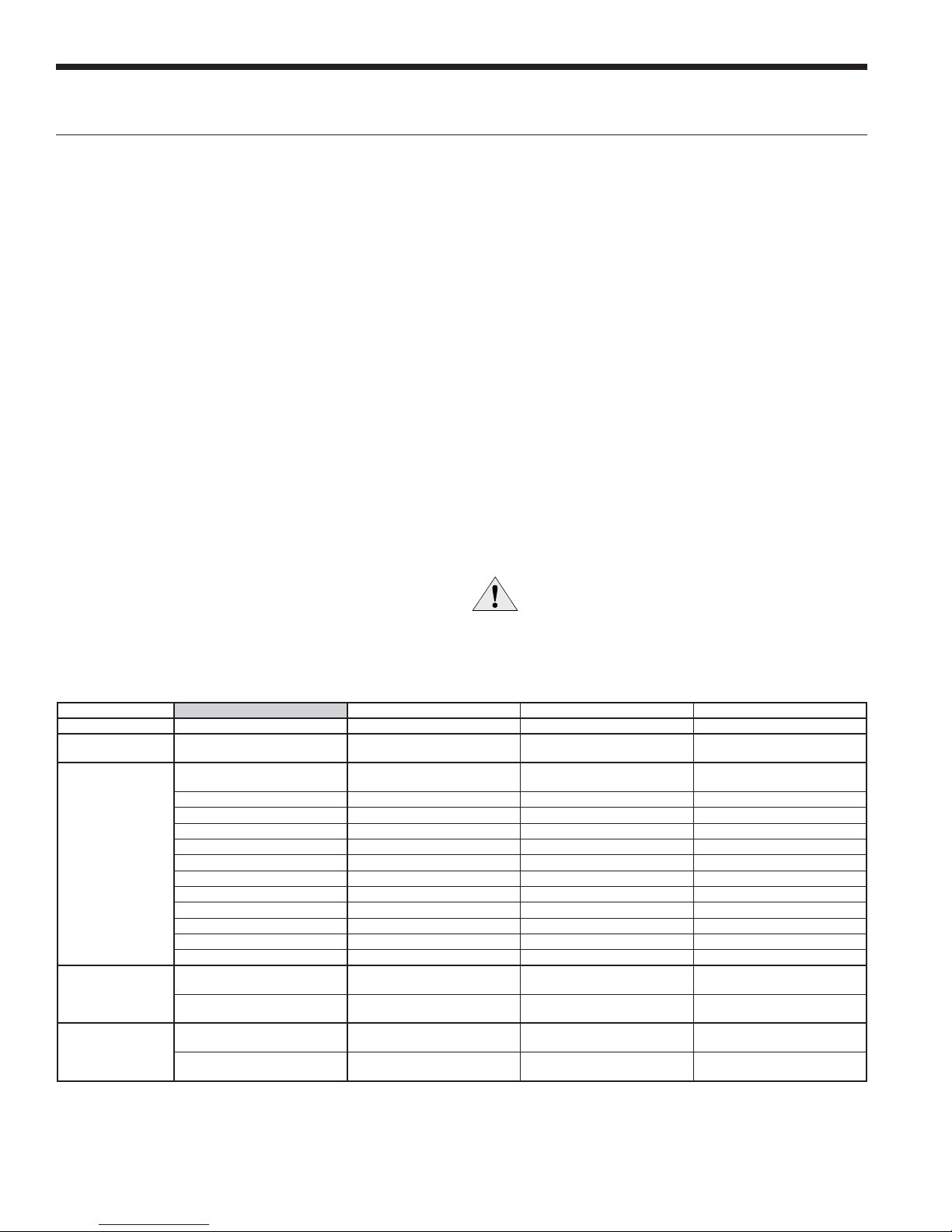
Water Quality Guidelines
Material Copper 90/10 Cupronickel 316 Stainless Steel
pH Acidity/Alkalinity
Scaling
Corrosion
Iron Fouling
(Biological Growth)
Erosion
NOTES: Grains = ppm divided by 17
mg/L is equivalent to ppm
Calcium and
Magnesium Carbonate
Hydrogen Sulfide
Chlorine Less than 0.5 ppm Less than 0.5 ppm Less than 0.5 ppm
Chlorides Less than 20 ppm Less than 125 ppm Less than 300 ppm
Carbon Dioxide Less than 50 ppm 10 - 50 ppm 10 - 50 ppm
Ammonia Less than 2 ppm Less than 2 ppm Less than 20 ppm
Ammonia Chloride Less than 0.5 ppm Less than 0.5 ppm Less than 0.5 ppm
Ammonia Nitrate Less than 0.5 ppm Less than 0.5 ppm Less than 0.5 ppm
Ammonia Hydroxide Less than 0.5 ppm Less than 0.5 ppm Less than 0.5 ppm
Ammonia Sulfate Less than 0.5 ppm Less than 0.5 ppm Less than 0.5 ppm
Total Dissolved Solids (TDS) Less than 1000 ppm 1000 - 1500 ppm 1000 - 1500 ppm
LSI Index +0.5 to -0.5 +0.5 to -0.5 +0.5 to -0.5
Iron, FE
Bacterial Iron Potential
Iron Oxide
Suspended Solids
Threshold Velocity
(Fresh Water)
Less than 0.5 ppm (rotten egg
smell appears at 0.5 ppm)
Sulfates Less than 125 ppm Less than 125 ppm Less than 200 ppm
2
+ (Ferrous)
Less than 1 ppm, above this
level deposition will occur
Less than 10 ppm and filtered
for max. of 600 micron size
7 - 9 7 - 9 7 - 9
(Total Hardness)
less than 350 ppm
< 0.2 ppm < 0.2 ppm < 0.2 ppm
< 1.8 m/sec < 1.8 m/sec < 1.8 m/sec
(Total Hardness)
less than 350 ppm
10 - 50 ppm Less than 1 ppm
Less than 1 ppm, above this
level deposition will occur
Less than 10 ppm and filtered
for max. of 600 micron size
(Total Hardness)
less than 350 ppm
Less than 1 ppm, above this
level deposition will occur
Less than 10 ppm and filtered
for max. of 600 micron size
2/22/12
6
Field Connected Water Piping
VERSATEC ULTRA NSKW INSTALLATION MANUAL
General
Each unit is equipped with captive FPT water connections
to eliminate ‘egg-shaping’ from use of a backup wrench.
For making the water connections to the unit, a Teflon tape
thread sealant is recommended to minimize internal fouling
of the piping. Do not over tighten connections. All supply and
return water piping should be insulated to prevent excess
condensation from forming on the water lines.
NOTES: 1) WaterFurnace recommends a male national pipe
thread (NPT) to British standard pipe fitting (BSPF) to
adapt to NSKW water connections. 2) Units are factory runtested using propylene glycol. Prior to connecting piping
to unit, thoroughly flush heat exchangers.
The piping installation should provide service personnel with
the ability to measure water temperatures and pressures.
The water lines should be routed so as not to interfere with
access to the unit. The use of a short length of high pressure
hose with a swivel type fitting may simplify the connections
and prevent vibration. Optional stainless steel hose kits are
available as an accessory item.
Before final connection to the unit, the supply and return
hose kits must be connected, and the system flushed
to remove dirt, piping chips and other foreign material.
Normally, a combination balancing and close-off (ball) valve
is installed at the return, and a rated gate or ball valve is
installed at the supply. The return valve can be adjusted to
obtain the proper water flow. The valves allow the unit to be
removed for servicing.
The proper water flow must be delivered to each unit
whenever the unit heats or cools. To assure proper flow,
the use of pressure/temperature ports is recommended
to determine the flow rate. These ports should be located
adjacent to the supply and return connections on the unit.
The proper flow rate cannot be accurately set without
measuring the water pressure drop through the refrigerantto-water heat exchanger (See Pressure Drop Table for water
flow and pressure drop information). Normally about 0.054
L/s flow rate per kw of cooling capacity (0.040 L/s per kw
minimum) is needed. Both source as well as load fluid piping
must be at least as large as the unit connections on the heat
pump (larger on long runs).
Never use flexible hoses of a smaller inside diameter than
that of the water connection on the unit and limit hose length
to 3.05m per connection. Check carefully for water leaks.
CAUTION: Water piping exposed to outside
temperature may be subject to freezing.
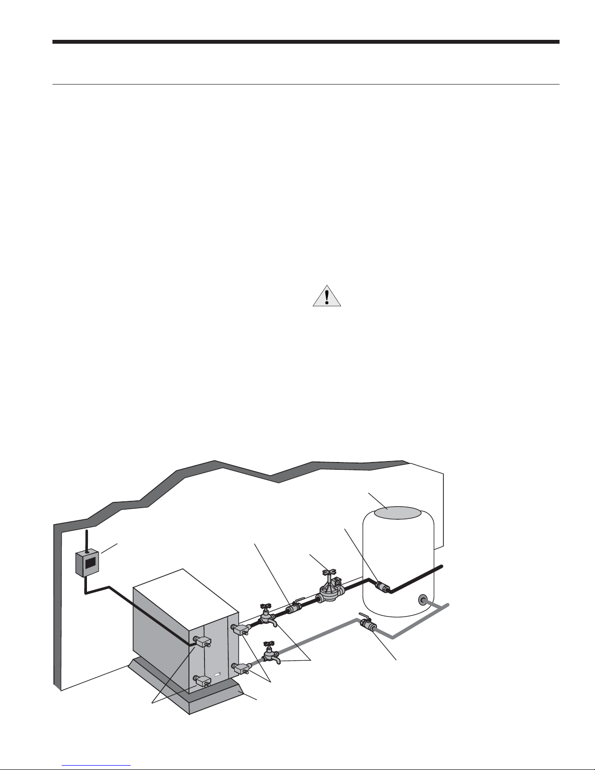
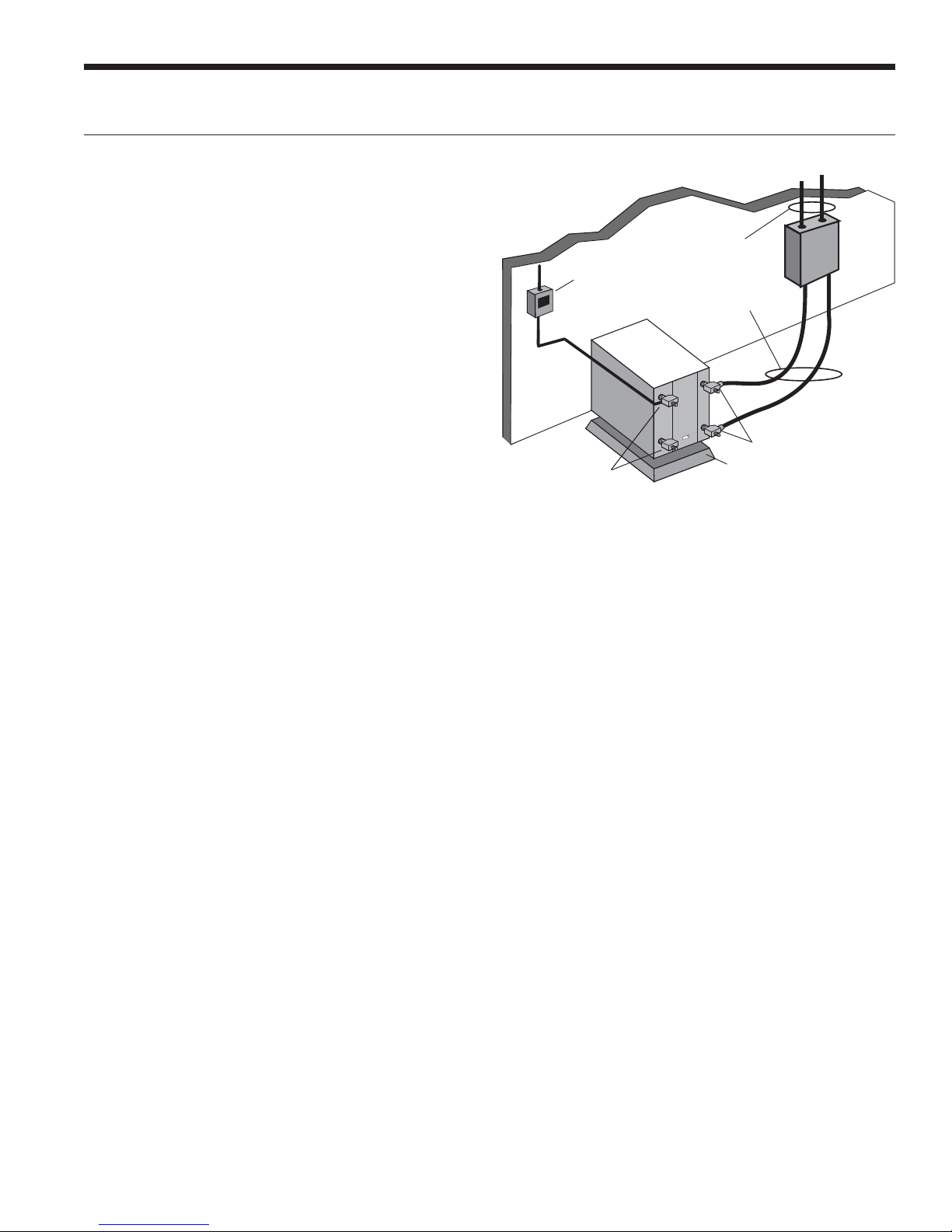
Typical Open Loop Installation
Line Voltage
Disconnect
Load Liquid
Connections
Shut-off Valve
(to isolate solenoid
valve while acid
flushing)
Rubber Bladder
Expansion Tank
Flow Regulator Valve
Solenoid
Valve
Boiler Drains for
HX Flushing
P/T Plugs
Vibration Absorbing
Mesh or Air Pad
Water Out
Water In
Shut-off
Valve
NOTE: Valves and boiler drains must be installed
so the heat exchanger can be acid flushed.
7

VERSATEC ULTRA NSKW INSTALLATION MANUAL
Field Connected Water Piping cont.
Open Loop Well Water Systems
Always maintain water pressure in the heat exchanger by
placing water control valves at the outlet of the unit. Use
a closed bladder type expansion tank to minimize mineral
deposits. Ensure proper water flow through the unit by
checking pressure drop across the heat exchanger and
comparing it to the figures in the pressure drop table.
Normally, about 0.038 L/s per kW flow rate of cooling
capacity is needed in open loop systems, 0.029 L/s per kW
minimum if entering source temperature is above 10°C.
Some water control valves draw their power directly from
the unit’s 24V transformer and can overload and possibly
burn out the transformer. Check total VA draw of the water
valve(s) and ensure it is under 40 VA.
Discharge water from a heat pump can be disposed of in
various ways depending on local building codes (i.e. recharge
well, storm sewer, drain field, adjacent stream or pond,
etc.). Most local codes restrict the use of sanitary sewer for
disposal. Consult your local building and zoning departments
to ensure compliance in your area.
Figure 9a: Open Loop Solenoid Valve Connection Option
Typical quick operating external 24V water solenoid valve
(type PPV100 or BPV100) wiring.
C
P1
R
SV
Solenoid
Acc Com
Acc NC
Acc NO
ABC Board
1
2
P2
3
Valve
NOTE: SW2-4 and SW2-5 should be “OFF” to cycle with
the compressor.
Figure 9b: Open Loop Solenoid Valve Connection Option
Typical slow operating external 24V water solenoid valve
(type V100FPT) wiring.
C
R
C
W/Y
Acc Com
ACC NC
Acc NO
V Valve ABC Board
NOTE: SW2-4 should be “ON” and SW2-5 should be “OFF”
when using a slow opening (V100FPT) water valve.
8
Field Connected Water Piping cont.
VERSATEC ULTRA NSKW INSTALLATION MANUAL
Earth Coupled Systems with Flow Center
nce piping is completed between the unit, flow center and
the earth loop, final purging and charging of the loop is
needed. A pump capable of 14 m
3
/hr @ 25 meters of head
is needed to achieve adequate flow velocity in the loop to
purge air and dirt particles from the loop itself. Antifreeze
solution is used in most areas to prevent freezing. Maintain
the pH in the 7.6-8.2 range for final charging.
Flush the system adequately to remove as much air as
possible. Then, pressurize the loop to a static pressure of
345-517 kPa. This is normally adequate for good system
operation. Ensure that the flow center provides adequate
flow through the unit by checking pressure drop across the
heat exchanger and by comparing it to the figures shown
in the Pressure Drop tables. Usually, 0.054 L/s per kW or
minimum 0.040 L/s per kW of cooling capacity is needed in
closed loop earth-coupled applications.
Ground Loop Design and Installation
This instruction manual does not cover the design and
installation of the ground loop system. WaterFurnace
recommends that all ground loops are designed using
GeoLink
software package. Installers shall follow the guidelines
detailed in Microgeneration Certification Scheme (MCS)
Installation Standard MIS 3005 for designing ground loop
collectors. Additional guidance on ground collectors is
provided by International Ground-Source Heat Pump
Association (IGSHPA).
TM
Design Studio (GDS) or another commercial
Typical Closed Loop Earth Coupled Installation
Earth Coupled Loop
Piping with Insulation
Line Voltage
Disconnect
Unit Connector Kits
with Insulation
P/T Plugs
Load Liquid
Connections
Vibration Absorbing
Mesh or Air Pad
9
VERSATEC ULTRA NSKW INSTALLATION MANUAL
Potable Water Systems
TNSKW06 kW heat pumps can be equipped with a double-
wall vented coaxial heat exchanger capable of hot water
generation (HWG). An optional factory-installed hot water
generator coil may be provided with NSKW08-17. The
temperature of the hot water produced by the heat pump
cannot be adjusted and will vary with the inlet temperature.
WaterFurnace recommends the use of a properly sized
buffer tank equipped with supplemental electric immersion
heaters in conjunction with all NSKW models used in an
HWG application. Immersion heaters must be capable
of heating the water to 60°C at a regular time interval
to prevent the build-up of bacteria such as Legionella.
Installations must meet minimum requirements outlined in
UK Domestic Heating Compliance Guide.
CAUTION: Hot water in excess of 60°C can cause
scalding.
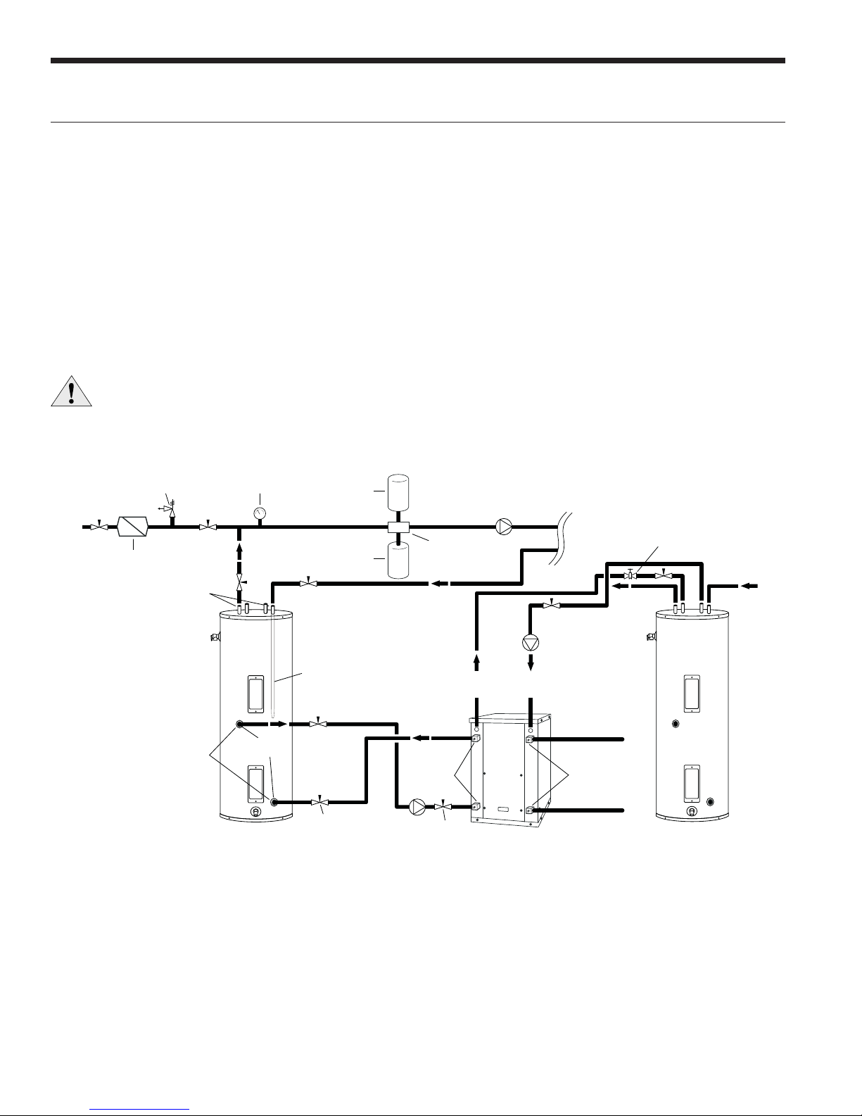
Suggested Domestic Water Heater Hookup
207 kPa
RELIEF VALVE
Back Flow Preventer /
Pressure Relief Valve
Dielectric
Unions
Dielectric
Unions
NOTES:
* A 207 kPa pressure relief valve (Part No: SRV30) should be used in
hydronic applications.
** Vent valve or P/T port at highest point in return line prior to ball valve.
Pressure
Gauge
GEO
STORAGE
TANK
1-1/2 in.
FPT
Dip Tube
Expansion
Tank
Ball Valve
Air
Vent
Air
Separator
Ball Valve
LOAD PUMP
FROM
HWG
Versatec Ultra
5 Series
TO
HWG
HYDRONIC
PUMP
Source OUT
P/T PortsP/T Ports
Source IN
LOAD
HOT
(Piped in
series to
an electric
water heater)
Vent Valve/
P/T Port**
DOMESTIC
COLD
10
Potable Water Systems cont.
Hot Water Generator Connections
The heat reclaiming hot water generator coil is vented double-
wall copper construction and is suitable for potable water. To
maximize the benefits of the hot water generator a minimum
50-gallon water heater is recommended. For higher demand
applications, use an 80-gallon water heater as shown below or
two 50-gallon water heaters connected in a series. A geo storage
tank should not be used in this application unless it is plumbed
in a series with an electric water heater. The geo storage tank is
equipped with a single 4500 Watt element and will not be able
to provide adequate water heating if used as a standalone water
heater. Electric water heaters are recommended. Make sure all
local electrical and plumbing codes are met for installing a hot
water generator. The Versatec Ultra NSKW is not supplied with
an internal circulator.
VERSATEC ULTRA NSKW INSTALLATION MANUAL
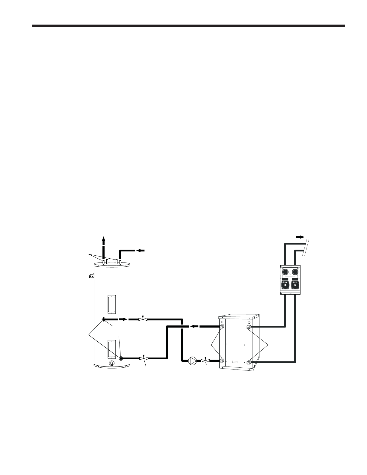
Alternate Hot Water Installation with
Direct Coupling to a Double Wall Unit
Dielectric
Unions
Dielectric
Unions
HOT
COLD
1-1/2˝
FPT
WaterFurnace
GEOTANK
Ball Valve
LOOP FIELD
FLOW CENTER
P/T PortsP/T Ports
Ball Valve
5 Series
NSW018 or NSW025 (Heating Only)
Versatec Ultra
06 (Heating Only)
with Double Wall Load Coax
NOTES:
1) Unions and valves must be installed so that acid flushing
of the heat exchanger is possible.
2)
Make sure there is not a check valve in the diptube of
the tank.
11

VERSATEC ULTRA NSKW INSTALLATION MANUAL
Hydronic Section
General guidelines are shown below for component
selection and design/installation criteria for the piping
system. Local codes supersede any recommendations in
this manual.
Shut Off/Flow Regulation Valves
Use full port ball valves or gate valves for component
isolation. If valves are going to be used frequently, ball
valves are recommended. Globe valves are designed for flow
regulation. Always install globe valves in the correct direction
(fluid should enter through the lower body chamber).
Check valves
Swing check valves must be installed in the horizontal
position with the bonnet of the valve upright. Spring check
valves can be mounted in any position. A flow check valve
is required to prevent thermo-siphoning (or gravity flow)
when the circulator pump is off or when there are two
circulators on the same system.
Storage (Buffer) Tank
A buffer tank is required for all hydronic heating systems
using Versatec Ultra heat pumps. The tank should be sized
to provide 7.6 L of storage capacity for every 300 W of
nominal heat pump capacity.
Pressure Reducing Valves or Feed Water Valves
This valve lowers the pressure from the make-up water line
to the system. Most are adjustable and directional. A “fast
fill” valve is required for initial filling of the system. Some
have screens, which must be cleaned after the initial filling.
If there is a restriction in the screen, the system could go to
0 kPa, potentially causing pumps(s) failure. A valve should
be installed on each side of the pressure reducing valve for
servicing. Both valves should have tags reading “Do not
shut this valve under normal operation – service valve only.”
Expansion Tanks
Expansion tanks are required on hydronic systems to help
absorb the pressure swings as the temperature in the
system fluctuates.
Elbows/Tees
Long radius elbows or two 45° elbows will lower pressure
drop. Standard tees have a greater restriction on the “T”
portion than tees designed with angled outlet ports.
Antifreeze
Antifreeze is required if any of the piping system is located
in areas subject to freezing.
Pressure Relief Valve
Most codes require the use of a pressure relief valve if a
closed loop heat source can be isolated by valves. Even
if local code does not require this device, WaterFurnace
recommends its installation. If the pressure relief valve in
the buffer tank is not already rated at 207 kPa maximum
pressure, one must be installed. The pressure relief valve
should be tested at start up for operation. Note that the
waste pipe must be at least the same diameter as the valve
outlet (never reduce), and valves may not be added to this
pipe. The bottom of the pipe must terminate at least 15 cm
above the floor. If the piping is connected to a drain, there
must be an air gap.
Backflow Prevention Check Valves
Most codes require backflow prevention check valves.
Note that a single check valve is not equal to a backflow
prevention check valve. Even if local code does not require
this device, WaterFurnace recommends its installation. This
is particularly important if the system will use antifreeze.
Dielectric Unions
Dielectric unions are recommended whenever connecting
two dissimilar metals to one and other to prevent electrogalvanic corrosion.
When using the various types of hydronic heat distribution
systems, the temperature limits of the geothermal system
must be a major consideration. In new construction, the
distribution system can easily be designed with the
temperature limits in mind. In retrofits, care must be
taken to address the operating temperature limits of the
existing distribution system. The maximum storage tank
temperature for the Versatec Ultra NSKW is 54.4°C. Typical
in floor radiant systems require much lower temperatures,
typically 37.8°-46.1°C, which is ideal for the Versatec Ultra
NSKW.
12
Hydronic Section cont.
VERSATEC ULTRA NSKW INSTALLATION MANUAL
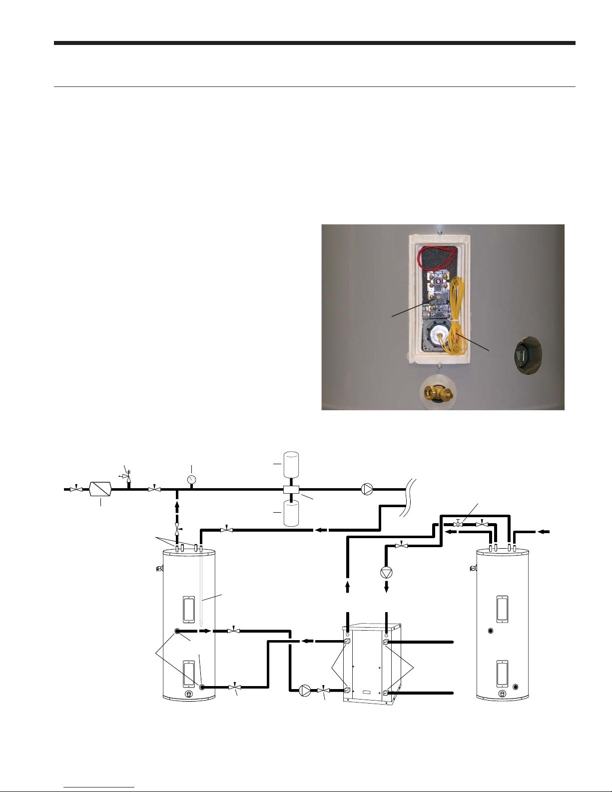
If using a Geothermal Storage tank there will be two red
wires exiting out of the top of the tank. These red wries
extend internally down to the thermistor/tank thermostat
section of the tank. Remove the bottom tank cover to expose
the red wires as well as the yellow tank thermistor wires.
HydroZone
If using HydroZone control, connect the two red wires to
the two yellow wires using wire nuts. Next, connect the two
red wires from the top of the Geothermal Storage tank to
“TS” and “GND” on the HydroZone. The “OAT” and “GND”
terminals on the HydroZone are used for an outdoor air
sensor.
HydroStat
If using HydroStat control, connect the two red wires to the
yellow wires using wire nuts. Next, connect the two red wires
from the top of the Geothermal Storage tank to “TS” and
“GND” on the HydroStat. The “OAT” and “GND” terminals
on the HydroStat are used to connect the controller to the
ELWT (Entering Load Water Temperature) well point sensor.
This sensor is located on the load side entering water line
inside the unit.
For other field installed controllers, these two red wires
will need wired to the appropriate sensor input terminals.
Another option for connection is to connect the thermostat
on the Geothermal Storage tank directly to “R” and “Y1” on
the ABC board.
Adequate rate of flow (L/s) is very important to system
performance and long term reliability. Follow the guidelines
for recommended flow in the recommendations table.
Geothermal Storage Tank Thermostat and Thermistor
Combination
Unit
Water To
Wat er
Thermistor Wires Connected to TS and GND on
HydroZone Controller.
207 kPa
RELIEF VALVE
Back Flow Preventer /
Pressure Relief Valve
Dielectric
Unions
Dielectric
Unions
NOTES:
* A 207 kPa pressure relief valve (Part No: SRV30) should be used in
hydronic applications.
** Vent valve or P/T port at highest point in return line prior to ball valve.
Pressure
Gauge
GEO
STORAGE
TANK
1-1/2 in.
FPT
Dip Tube
Ball Valve
Expansion
Tank
Air
Vent
Air
Separator
Ball Valve
LOAD PUMP
FROM
HWG
Versatec Ultra
5 Series
TO
HWG
HYDRONIC
PUMP
Source OUT
P/T PortsP/T Ports
Source IN
LOAD
HOT
(Piped in
series to
an electric
water heater)
Vent Valve/
P/T Port**
DOMESTIC
COLD
13
VERSATEC ULTRA NSKW INSTALLATION MANUAL
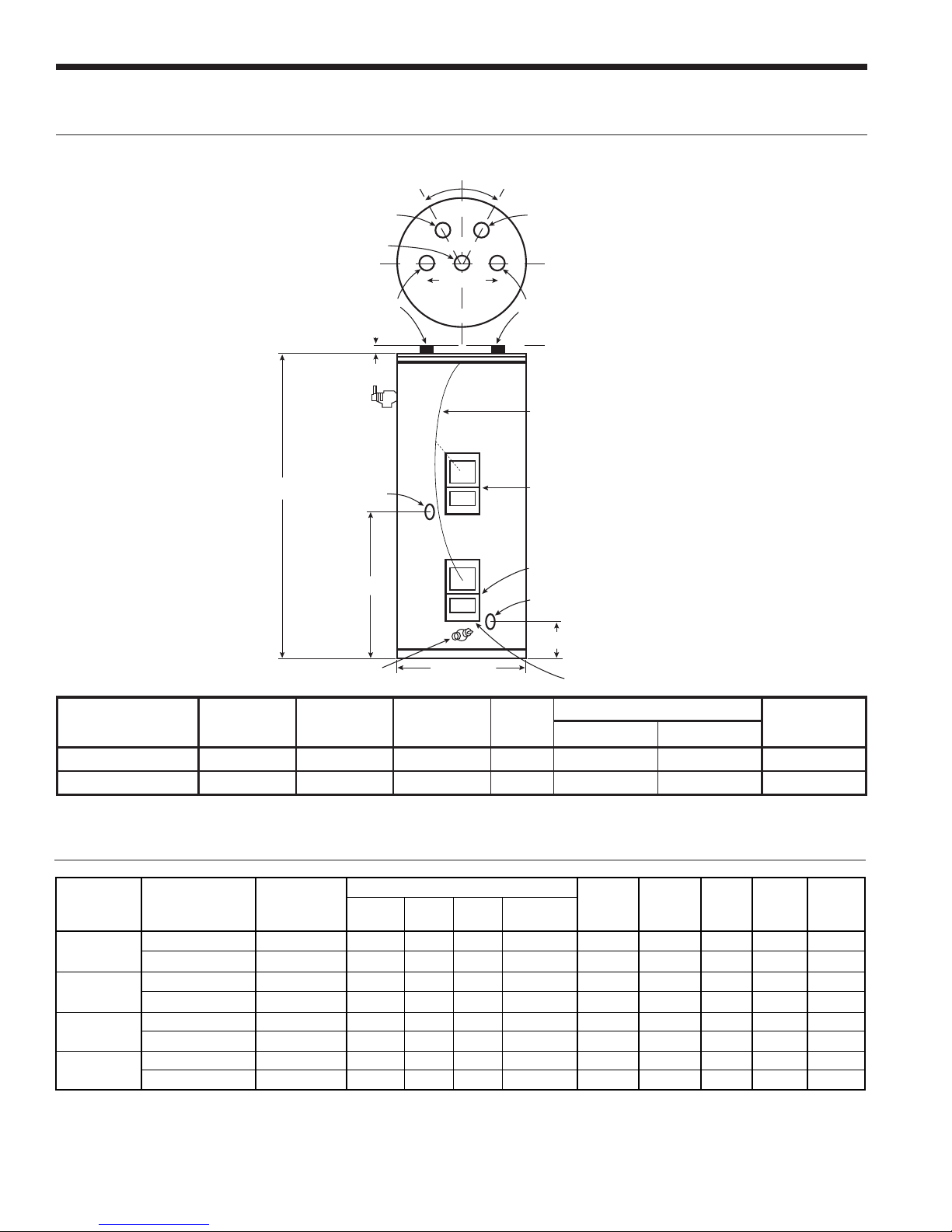
Accessories and Options
Geo Storage Tank Dimensions
°
3
0
0
3
°
From Geo
PRIMARY ANODE
99 cm - 80 Gallon
106.7 cm - 119 Gallon
HOT OUTLET
w/35.6 cm SECONDARY ANODE
Approx. 2.54 cm
T & P
VALVE
HEIGHT
90.8 cm
To Geo 150 cm Dip Tube
20.3 cm
COLD INLET
132.0 cm DIP TUBE
Yellow Wire attached
to Thermistor or Thermostat
for Top Exit
Element Location
Lower Sensor Thermistor (12P541-01)
to be used by Water to Water Units
Optional “From Geo” Connection
13.3 cm
DRAIN VALVE
Model
Number
GEO-STORAGE-80
GEO-STORAGE-120
Gallon [Liter]
Capacity
80 [303] 4500 1 16 160.6 61.0 92.5
119 [450] 4500 1 16 160.6 71.1 141.1
Element
Wattage
(240 Volt)
Electrical Data
Model
06
08
12
17
Rated
Voltage
220-240/50/1 198/264 17.5 11.2 60.0 24.0 1.5 4.5 17.2 20.0 30
380-420/50/3 342/462 6.5 4.2 28.0 16.8 - - 4.2 5.3 6
220-240/50/1 198/264 27.0 17.3 97.0 34.0 1.5 4.5 23.3 27.6 40
380-420/50/3 342/462 10.0 6.4 45.0 27.0 - - 6.4 8.0 10
220-240/50/1 198/264 31.5 20.2 126.0 44.0 1.5 4.5 26.2 31.2 50
380-420/50/3 342/462 12.1 7.8 51.5 31.0 - - 7.8 9.8 15
220-240/50/1 198/264 45.0 29.0 130.0 46.0 1.5 4.5 35.0 42.3 70
380-420/50/3 342/462 19.0 12.2 87.0 52.0 - - 12.2 15.3 25
Notes:
* - With optional IntelliStart, Type D MCB recommended
Voltage
Min/Max
MCC RLA LRA LRA*
DIAMETER
Number
of
Elements
Compressor
R
Value
Lower Thermostat
Dimensions in cm
Height Diameter
Load
Pump
FLA
Source
Pump
FLA
Total
Unit
FLA
Approx Shipping
Weight kg
Min
Circ
Amp
Max
Fuse/
HACR
1/15/15
14
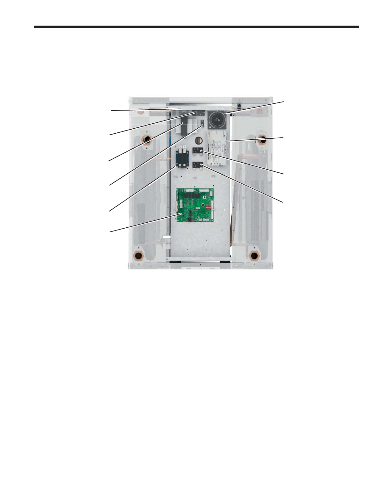
Electrical Data cont.
Control Box
Circuit Breakers
VERSATEC ULTRA NSKW INSTALLATION MANUAL
Run Capacitor
Load Pump Relay
Transformer
Ground Lug
Compressor Contactor
Aurora Base Control
Board (ABC)
Accessory Relay
A set of “dry” contacts has been provided to control
accessory devices, such as water solenoid valves on open
loop installations, electronic air cleaners, humidifiers, etc.
This relay contact should be used only with 24 volt signals
and not line voltage power. The relay has both normally
open and normally closed contacts and can operate with
either the fan or the compressor. Use DIP switch SW2-4
and 5 to cycle the relay with blower, compressor, or control
a slow opening water valve. The relay contacts are available
on terminals #1 and #3 for normally closed, and #2 and #3
for normally open on P2.
When powering high VA draw components, or V type open
loop water valves, R should be taken ‘pre-fuse’ from the ‘R’
quick connect on the ABC board and not the ‘post-fuse’ ‘R’
terminal on the thermostat connection. If not, blown ABC
fuses might result.
Optional IntelliStart
Load Pump Power Block
Source Pump Power Block
Control Box Relocation
The control box can be installed on the rear of the unit. To
relocate the control box, follow the procedures below.
1. Remove all power sources to the unit.
2. Remove the unit’s top panel.
3. Cut all plastic wire ties to the following:
a) High pressure switch (black wires)
b) Low pressure switch (blue wires)
c) Freeze sensing and Thermistors
d) Compressor wires
4. Remove the four screws from the control box.
5. Relocate the control box to opposite end of the unit.
6. Using the screws removed in step 4 above, reattach the
control box.
7. Move the RS485 Keystone Coupler to the opening on the
back side of the unit.
8. Secure all wires so they do not come in contact with
refrigerant lines.
9. Replace the top of the unit.
10. Replace both access panels.
11. Reapply power sources.
15
 Loading...