

WaterFurnace IntelliZone2 ZoneStat, IntelliZone2 SensorStat Instruction Manual
Instruction Guide:
IntelliZone2 ZoneStat and SensorStat
INSTRUCTION GUIDE: ZONESTAT AND SENSORSTAT
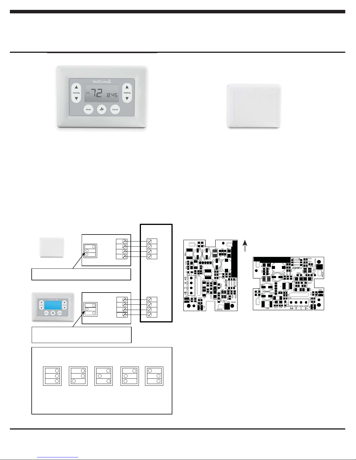
IntelliZone2 ZoneStat
ZoneStat Installation Instructions
1. Remove the cover from the ZoneStat and attach the
backplate to the wall making sure the thermostat is level.
2. Connect 4 conductor (minimum 18 gauge) wire from the
ZoneStat to IntelliZone2.
3. Zone ID must be set for each Zone (2-6) using the DIP
switches on the PCB. See the Zone ID Codes illustration
for configuration options. Zone ID can be confirmed on the
ZoneStat by pressing the cancel button for 5 seconds.
4. Seal the hole in the wall to prevent air leaks and replace the
front cover.
SensorStat
On
3
2
1
Zone 5 code shown
Zone ID must be set for each Zone 2-6. ID cannot be
confirmed on Zone SensorStat. See Zone ID Codes.
A+
R
C
B-
Zone 5 Stat
ZoneStat
On
3
2
1
Zone 4 code shown
Zone ID must be set for each Zone 2-6. ID can be
confirmed on ZoneStat by pressing cancel button for
5 sec. ID shown on display. See Zone ID Codes.
A+
R
C
Zone 3 Stat
B-
IntelliZone2
Relay Board
A+
R
C
B-
P15 – Zone 5
A+
R
C
B-
P14 – Zone 4
IntelliZone2 SensorStat
SensorStat Installation Instructions
1. Remove the cover from the SensorStat and attach the
backplate to the wall in one of the two orientations shown
below.
2. Connect 4 conductor (minimum 18 gauge) wire from the
SensorStat to IntelliZone2.
3. Zone ID must be set for each Zone (2-6) using the DIP
switches on the PCB. See the Zone ID Codes illustration for
configuration options.
4. Seal the hole in the wall to prevent air leaks and replace the
front cover.
SensorStat Installation Orientation
SensorStat Board
UP
NOTE: The SensorStat must be installed in one of the two orientations
shown above for the most accurate temperature sensing.
Zone ID Codes
Zone 2
On
NOTES:
1) Zone ID must be set for each Zone 2-6. ID can be confirmed on ZoneStat
by pressing cancel button for 5 sec. ID shown on display.
2) Small screw driver can be used to set ID thru protective plastic skin!
3) MasterStat always Zone 1. Zone ID not necessary.
IG1603EW 10/12 997-012330-2-R Rev B
On
3
2
1
Zone 4 Zone 5Zone 3
On
3
2
1
3
2
1
On
Zone 6
On
3
2
1
3
2
1
1
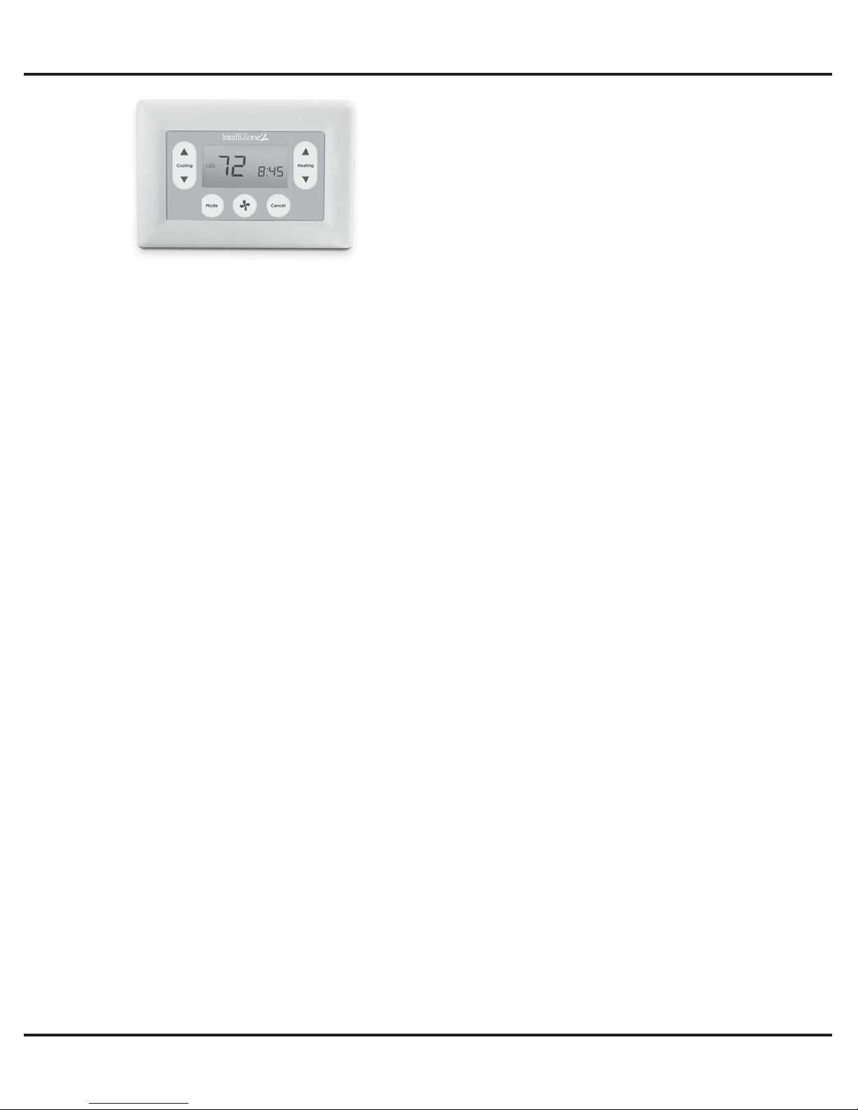
IntelliZone2 ZoneStat
ZoneStat Operating Instructions
INSTRUCTION GUIDE: ZONESTAT AND SENSORSTAT
Backlight – Backlighting is activated whenever a key is pressed
and remains on for 5 seconds.
Mode Button – Allows selection of modes: Off, Auto, Heat and
Cool. Pressing the mode button moves selection between the
available modes for the zone.
Fan Button - Pressing the FAN button will toggle the fan mode
from auto mode, which runs the fan when a call for heat or cool
occurs, continuous mode, or intermittent fan mode. Continuous
Fan runs the fan continuously in the zone. Intermittent fan mode
allows selection of fan on and off time in the zone.
Pressing the RIGHT ARROW button toggles between
adjustment of the fan on and fan off times in intermittent fan
mode. In fan on time adjustment, “on” will be displayed in the
smaller 7-segment area to the right of the SET icon. In fan off
time adjustment, “off” will be displayed in the smaller 7-segment
area. Pressing the UP ARROW or DOWN ARROW buttons
in intermittent mode shall adjust the on and off fan times by 5
minutes at a time.
If in programmable mode, adjusting the fan mode or interval
from the current schedule settings will cause the control to enter
a “hold”.
Auto Mode Display - When Heating mode is active the HEAT
icon and the triangle next to the HEAT icon are flashing. When
Cooling mode is active the COOL icon and the triangle next to
the COOL icon are flashing.
Heat Mode Display - When Heating mode is active the triangle
next to the HEAT icon is energized. The HOLD icon is energized
if a temperature override or a fan override is active. A temperature
override is set if the set point is adjusted from the schedule set
point in programmable mode. A fan override is set if the fan
setting is adjusted from the schedule setting in programmable
mode. When Emergency Heat or Auxiliary Heat are active, the
triangle next to the HEAT icon is flashed ON and OFF.
Cool Mode Display - When Cooling mode is active the
triangle next to the COOL icon is energized. The HOLD icon is
energized if a temperature override or a fan override is active.
A temperature override is set if the set point is adjusted from
the schedule set point in programmable mode. A fan override
is set if the fan setting is adjusted from the schedule setting in
programmable mode.
NOTE: Zone ID can be confirmed on the ZoneStat by pressing
the cancel button for 5 seconds.
Set Point Display - The set point that can be adjusted with the
up or down buttons is located in the larger segments under the
SET TEMP segment. In AUTO mode, the Set point screen will
display two set points for HEAT and COOL. The set point that
can be adjusted is displayed on the left in larger digits and the
other set point is displayed on the right side in smaller digits. To
switch between the two set points, press the right arrow button.
©2012 The Manufacturer has a policy of continual product research and development and reserves the right to change design and specifi cations without notice.
IG1603EW 10/12 997-012330-2-R Rev B
2
 Loading...