

WaterFurnace IntelliZone2 Installation Manual
Comfort Zoning System
Four Zone Capability
Designed for Use with Typical 24VAC Heat Pump Controllers
Installation Information
Damper Installation
Thermostat Installation
Electrical
Startup Procedures
IntelliZone2 ● 24V Installation Manual
Wiring Schematic
IM1678EW 12/16


Table of Contents
General Installation Information . . . . . . . . . . . . . . . . . . . . . . . . . . . . . . . . . . . . . . . . . . . . . . . . . . . . . 5
Damper Installation . . . . . . . . . . . . . . . . . . . . . . . . . . . . . . . . . . . . . . . . . . . . . . . . . . . . . . . . . . . . . . . . 6
Electrical Wiring. . . . . . . . . . . . . . . . . . . . . . . . . . . . . . . . . . . . . . . . . . . . . . . . . . . . . . . . . . . . . . . . . . . 9
Thermostat Installation. . . . . . . . . . . . . . . . . . . . . . . . . . . . . . . . . . . . . . . . . . . . . . . . . . . . . . . . . . . . .12
IntelliZone2 ● 24V Configuration . . . . . . . . . . . . . . . . . . . . . . . . . . . . . . . . . . . . . . . . . . . . . . . . . . . 14
Description of Operation . . . . . . . . . . . . . . . . . . . . . . . . . . . . . . . . . . . . . . . . . . . . . . . . . . . . . . . . . . 20
System Startup and Checkout. . . . . . . . . . . . . . . . . . . . . . . . . . . . . . . . . . . . . . . . . . . . . . . . . . . . . . 22
Wiring Schematic. . . . . . . . . . . . . . . . . . . . . . . . . . . . . . . . . . . . . . . . . . . . . . . . . . . . . . . . . . . . . . . . . 24
IntelliZone2 ● 24V Fault Codes . . . . . . . . . . . . . . . . . . . . . . . . . . . . . . . . . . . . . . . . . . . . . . . . . . . . . 26
Revision Guide . . . . . . . . . . . . . . . . . . . . . . . . . . . . . . . . . . . . . . . . . . . . . . . . . . . . . . . . . . . . . . . . . . . 28
INTELLIZONE2 ● 24V INSTALLATION MANUAL
INTELLIZONE2 ● 24V INSTALLATION MANUAL
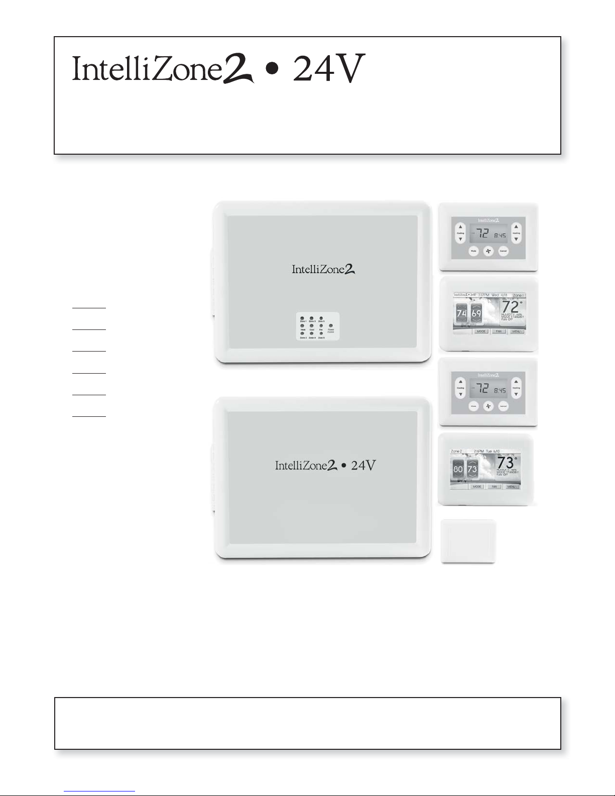
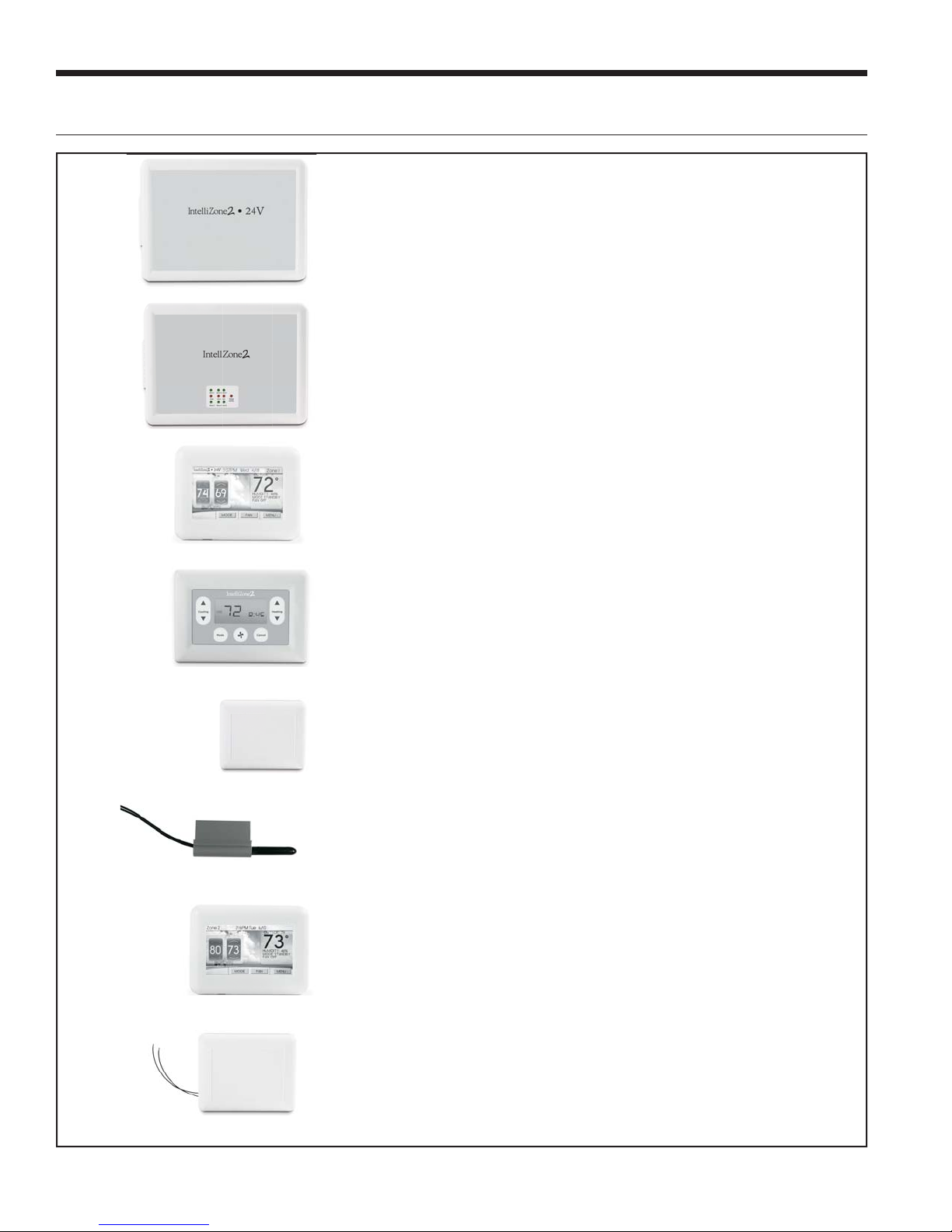
IntelliZone2 ● 24V Components
IntelliZone2 ● 24V Conversion Board
The IntelliZone2 ● 24V conversion board communicates via Modbus with
the IntelliZone2 relay board and converts the Modbus communication into
typical 24VAC signals to be sent to the ABC or Premier heat pump control.
This zoning system is designed for use with non-communicating heat pump
controls.
IntelliZone2 Relay Board (Firmware Version 2.01 or Later)
The IntelliZone2 relay board provides basic relay logic for the damper
operation and serves as a common connection point for all IntelliZone2
thermostats and the heat pump.
IntelliZone2 MasterStat
The IntelliZone2 MasterStat is the master control for the system and has all
of the programming for operation. It is a 4.3 in. communicating color touch
screen device that also functions as a zone thermostat for Zone 1. Optional
remote sensor capability is also available.
IntelliZone2 ZoneStat
The IntelliZone2 ZoneStat is a zone thermostat option for any of Zones 2
through 4. It has full setback capability and communicates to the
IntelliZone2 system.
IntelliZone2 SensorStat
The IntelliZone2 SensorStat is a zone thermostat option for any of Zones 2
through 4. It has full setback capability (through the MasterStat interface
only) and communicates to the IntelliZone2 system.
IntelliZone2 Outdoor Sensor
The IntelliZone2 Outdoor Sensor measures the outdoor temperature and
communicates to the IntelliZone2 system. This temperature is displayed on
the MasterStat, and also used to balance response as well as auxiliary electric
heat use. The Outdoor Sensor is included in every kit.
TPCC32U01 (Optional) (Firmware Version 3.01 or Later)
The TPCC32U01 is a 4.3 in. communicating color touch screen device that
can be used as a zone thermostat for zones 2 through 6. It has full set back
capability and communicates to the IntelliZone2 System.
SensorStat-Remote-Kit (Optional)
The SensorStat-Remote-Kit is an option for an invisible thermostat installation
and communicates with the IntelliZone2 relay panel. The kit will include
the SensorStat Remote, TSU03 (mud in sensor) and wire nuts. This kit will
monitor the zone temperature in zones 2 through 6. All set point adjustments
are made at the MasterStat.
4
General Installation Information
D
INTELLIZONE2 ● 24V INSTALLATION MANUAL
Safety Considerations
Installing and servicing heating and air conditioning
equipment can be hazardous due to system electrical
components. Only trained and qualifi ed service personnel
should install, repair or service heating and air conditioning
equipment. When working on equipment, observe
precautions in the literature, tags and labels attached to the
unit, and other safety precautions that may apply. Follow all
safety codes. Wear safety glasses and work gloves.
WARNING: Before performing service or
maintenance operations on the system, turn
off main power switches to the indoor unit.
Turn off accessory heater power switch if
applicable. Electrical shock could cause
serious personal injury.
Delivery Information
When the equipment is received, all items should be
carefully checked against the bill of lading to be sure
all crates and cartons have been received. Examine the
contents for shipping damage, removing them from the
cartons if necessary. If any damage is noted, the carrier
should make the proper notation on the delivery receipt,
acknowledging the damage.
General rules to follow when installing a
zone system:
CAUTION: When installing the IntelliZone2 ● 24V
in a structure with fossil fuel (oil, gas, propane)
appliances, it is important that both supply and
return dampers are used in each zone to avoid
potential back-drafting of fossil-fueled appliances.
• Up to four zones with dual capacity units (two with
single-speed units).
• All dampers should be located as close to the main
trunk as possible to limit the amount of pressurized
trunk line and thus limit air leakage.
• No less than three branch runs in a zone to prevent
a single branch obstruction (curtains or clothes etc.)
from affecting unit airfl ow.
• Insulate and seal around rectangular dampers to
prevent leakage.
• All dampers must be wired with 18-gauge wire.
NOTE: Crimp connections should never be used on
solid conductor wire.
• Ensure that the transformer can handle the power
requirements of the system.
• No more than three dampers per zone.
• Ductboard-mounted dampers should be supported
within six inches of the damper due to the weight and
stress on the ductboard.
Installation and Design Steps
1. Decide which areas of a home or offi ce will comprise
each of the individual zones. A maximum of four
individual zones with dual capacity (two with singlespeed equipment) can be chosen.
2. Calculate loads using software or other
recognized methodology.
3. Use software to determine the equipment size and
performance based on the total heating and cooling
demands of the building, not the sum of the individual
zone demands.
4. Find the peak heating and cooling demands and the
peak cfm required for each of the zones.
5. Determine zone design air fl ow and zone size settings
using IntelliZone2 Design software.
6. Lay out and size the supply air ductwork and dampers.
Care should be taken to avoid under sizing either the
supply air systems, return air systems, or diffusers.
7. Decide where to locate the thermostats.
8. Install the unit and the IntelliZone2 ● 24V Comfort
Zoning system.
Zone Control Panels
Locate the IntelliZone2 and IntelliZone2 ● 24V panels in an
indoor area that has enough space for service personnel
to perform maintenance or repair. Provide sufficient room
to make electrical connection(s). The IntelliZone2 and
IntelliZone2 ● 24V is not approved for outdoor installation
and, therefore, must be installed inside the structure being
conditioned. Do not locate the control panels in areas
where ambient conditions are not maintained within 45°F
to 95°F and are greater than 75% relative humidity. The
IntelliZone2 and IntelliZone2 ● 24V control panels should
be mounted on or as close to the unit as possible by using
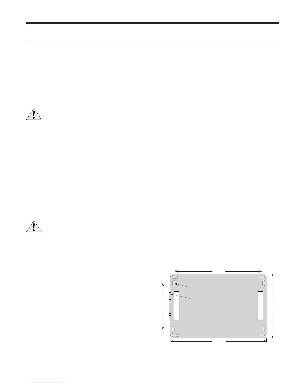
the mounting hardware provided. See Figure 1 for mounting
hole locations.
Figure 1: IntelliZone2 ● 24V and IntelliZone2 Relay Panel
9.25 in.
Mounting Slots
Hinge Side
6.00 in.
Wire Access
epth = 2.00 in. Deep with cover
10.35 in.
NOTE: Use longer screws (not provided) to penetrate
through drywall into stud.
Wire Access
7.75 in.
5
INTELLIZONE2 ● 24V INSTALLATION MANUAL
Damper Installation
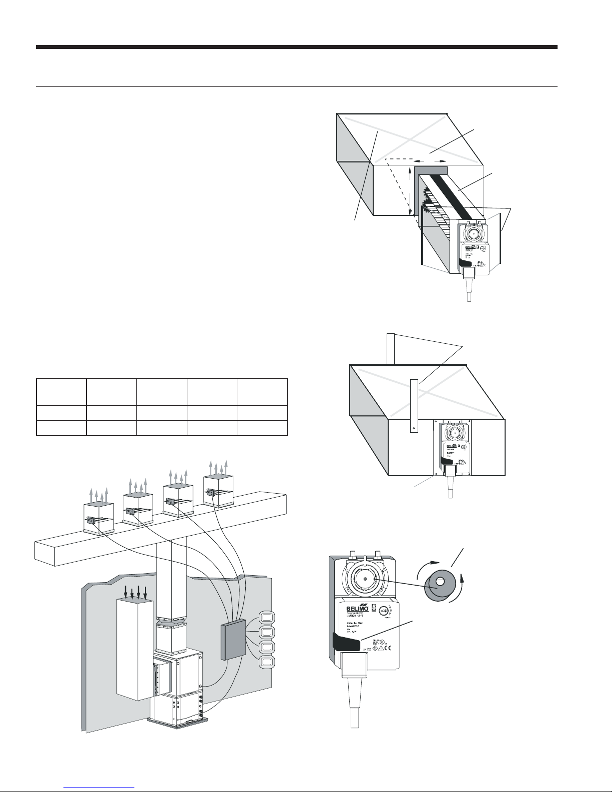
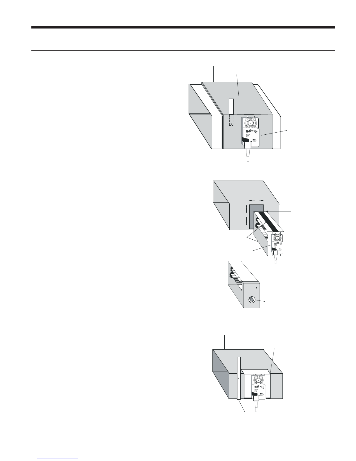
Installing Rectangular Dampers in
Metal Ductwork
1. Cut out dimensions A and B as shown in Figure 2 by
using sheet metal snips. NOTE: Dimensions A and B are
listed in the Dimensional Examples table.
2. Use foam insulation tape on the top and bottom of
the zone damper to prevent excessive air bypass. Also
check the cross emboss for excessive air bypass (see
Figure 2).
3. Slide the zone damper into the ductwork making
sure no obstructions will interfere with damper blade
operation.
4. Use the screws provided to mount the damper flange
to the ductwork. Four to six mounting holes are
provided as shown in Figure 3.
5. Use drive cleats or regular duct mounting brackets to
attach ductwork to joist within six inches on both sides
of the damper (see Figure 3).
6. Check damper blade operation for obstructions by
holding the manual release button and rotating the
damper shaft CCW (Open) and CW (Closed) 3 Wire
only as shown in Figure 4.
Dimensional Examples
Damper
Model
ZDR1024 10 in. 24 in. 10 in. 3.75 in.
ZDR0812 8 in. 12 in. 8 in. 3.75 in.
HWA B
Figure 2: Foam Taping Zone Damper
B
A
Cross emboss for
duct stiffness may
cause excessive
air bypass
Figure 3: Mounting Damper
Attach duct/damper
to joist within 6" on
3.75”
Foam Tape
(top and bottom)
Foam Seal
both sides
Four Zone System Representational Layout
Premier2
Mounting Screws
(4 places)
Figure 4: Checking Damper Blade for Obstructions
CCW
Open
72
72
72
72
Rotate by hand
CW
Closed
Manual release
6
Damper Installation cont.
INTELLIZONE2 ● 24V INSTALLATION MANUAL
Insulating Rectangular Dampers in
Metal Ductwork
Insulate ductwork as shown in Figure 5. All metal must
be covered. Care must be taken not to obstruct the shaft
from rotating when insulating. Do not insulate the zone
damper actuator.
Installing Rectangular Dampers
in Ductboard
1. Cut out dimensions A and B by using a ductboard
knife. NOTE: Dimensions A and B are listed in the
Dimensional Examples table.
2. A ductboard spacer should be installed on the end
of the damper frame as shown in Figure 6 to prevent
excessive air bypass. For example: A one-inch-thick,
8 in. x 20 in. ductboard and a 8 in. x 20 in. zone
damper would have a one-inch gap at the end of the
frame once it is installed without a ductboard spacer.
Use the piece cut out for installation.
3. Foam insulation tape should be used on the top and
bottom of the zone damper to prevent excessive air
bypass as shown in Figure 6.
4. Slide the zone damper into the ductboard making
sure no obstructions will interfere with damper
blade operation.
5. Tape the damper face flange to the ductboard using
foil tape making sure the damper is secure and air tight
as shown in Figure 7.
6. Support the full length of the ductboard underside
within six inches and on both sides of the damper as
shown in Figure 7.
7. Check the damper blade operation for obstructions
by holding the manual release button and rotating the
damper shaft CCW and CW (see Figure 4).
Figure 5: Insulating Rectangular Metal Ductwork
Duct wrap insulation
Do not insulate zone
damper actuator
Figure 6: Taping Zone Damper with Foam Tape
B
A
Foam tape
(top and bottom)
Insulate between
actuator and damper
Duct board
spacer
Keep spacer clear
of end bushing
Figure 7: Taping Damper Flange to Ductboard
Foil tape damper face
to ductboard
Support the full length of ductboard
underside within 6” of damper
7
INTELLIZONE2 ● 24V INSTALLATION MANUAL
Support with wide
steel strap
1-1/2’’ or 2’’ if in unconditioned space
Do not insulate
damper actuator
Flexible duct
Clamp with duct strap. Install screw no farther
than 1” from either end of damper
Slide duct 2-3’’ past
damper end rib
Air Flow
Damper Installation cont.
Insulating Rectangular Ductboard/
Metal Sleeve
Care must be taken not to obstruct the shaft from rotating
when insulating. Do not insulate the zone damper actuator.
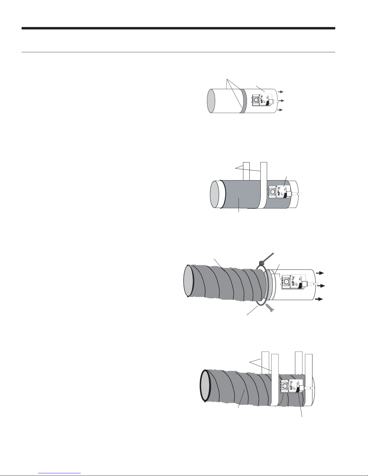
Installing Circular Dampers in Round
Metal Duct
1. Crimp the end of the duct that is the supply air to
damper. Insert into circular damper no more than
1.5 inches.
2. Fasten the duct to the damper with three screws.
Screws installed more than one inch from either end
may obstruct damper blade rotation.
3. Seal completely around the duct with metal duct tape
or mastic to prevent air leakage as shown in Figure 8.
4. Check the damper blade operation for obstructions by
holding the manual release button and rotating damper
shaft CCW and CW (3 wire only). See Figure 4.
5. Support the duct to joist within six inches of the
damper as shown in Figure 9.
Insulating Circular Dampers in Round
Metal Duct
Insulate ductwork as shown in Figure 9. All metal must be
covered to prevent condensation. Care must be taken not
to obstruct the shaft from rotating when insulating. Do not
insulate the zone damper actuator.
Figure 8: Taping Round Duct to Circular Damper
Three screws sealed
with duct tape or mastic
Manual release button
Air Flow
Figure 9: Supporting and Insulating Circular Damper
Support with
wide steel strap
1-1/2" or 2" if in unconditioned space
Figure 10: Attaching Flexible Duct to Damper
Do not insulate
damper actuator
Installing Circular Dampers in
Flexible Duct
1. Slide flexible duct two to three inches over the damper
pipe past the damper rib as shown in Figure 10.
2. Fasten duct to damper with a nylon duct strap,
screwing the strap to the pipe to prevent the duct from
slipping off. Screws installed more than one inch from
either end may obstruct damper rotation.
3. Seal completely around the duct with metal duct tape
or mastic to prevent any air leakage.
4. Check the damper blade operation for obstructions by
holding the manual release button and rotating damper
shaft CCW (Open) and CW (Closed) - 3 wire only. See
Figure 4.
5. Support the damper to joist within six inches on both
sides of the damper as shown in Figure 11.
Insulating Damper Actuators
Insulate the damper as shown in Figure 11. All metal must
be covered to prevent condensation. When insulating, care
must be taken not to obstruct the shaft from rotating. Do
not insulate the zone damper actuator.
Figure 11: Supporting and Insulating Circular Damper
8
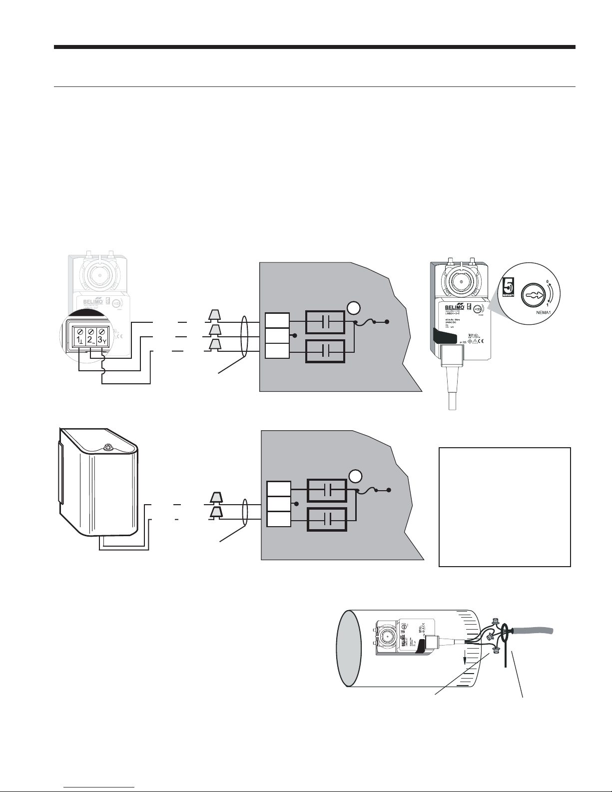
Electrical Wiring
Wire Nuts Strain Relief
3-Wire Damper
Zone 4
Com
Open
Close
G
Minimum
18-gauge wire
(Indicated rotation direction
is valid for switch position ‘0’ )
BlkCOM
Grn
CCW
Red
CW
IntelliZone2 PCB
2-Wire Damper
Minimum
18-gauge wire
Zone 4
IntelliZone2 PCB
Com
Open
Close
G
COM
Gray
CCW
Yellow
Wiring Damper Actuators
All wiring must comply with local and state codes.
Disconnect the power supply before beginning to wire to
prevent electrical shock or equipment damage. All wiring
should be run back to the control panel. Keep wires a
minimum of 12 inches from any high voltage lines. Follow
the damper wiring schematic as shown in Figure 12. Verify
that damper rotation direction is correct. The 3-wire
damper rotation direction is reversible with switch on front
cover.
Figure 12: Damper Actuator Wiring
INTELLIZONE2 ● 24V INSTALLATION MANUAL
Damper Actuator Wiring Notes
1. Minimum of 18-gauge thermostat wire is recommended.
2. Use wire nuts to connect the thermostat wire to the
actuator wire (solid wire to stranded wire) as shown in
Figure 13.
3. The actuator wiring should be secured using a wire tie to
prevent the wires from being separated (see Figure 13).
Figure 13: Actuator Wiring
9
Damper Switch
Reverse Rotation
Note:
Note:
1. Each zone must have
1. Each zone must have
dampers that match by
dampers that match by
manufacturer and type.
manufacturer and type.
2. Each IntelliZone
2. Each IntelliZone2•24V
System must have
System must have
dampers that match,
dampers that match
either 2-wire or 3-wire.
either 2-wire or 3-wire.
 Loading...